

Page 1
Page 2
Step 1
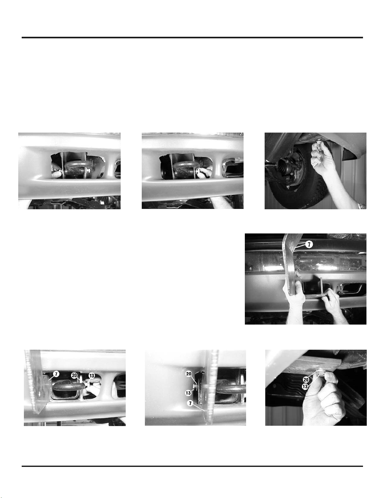
Note: It is not necessary to remove or modify the vehicle bumper to install this mounting kit.
Remove and discard the three M12 bolts that secure the vehicle tow hook. They are located on
either side and on the bottom of the tow hook (Figure 1). Remove the tow hook assembly and set it
aside.
Figure 1
Step 2
Install left hand bracket assembly #7. Bracket is inserted
through the existing tow hook access in the air dam (Figure 2).
Replace the vehicle tow hook and secure using (1) M12 x 1.75 x
50mm bolt #13 and lockwasher #20 through bracket assembly,
frame, and into tow hook at each side and bottom of vehicle
frame (Figure 3). Do not tighten hardware completely.
Figure 2
Figure 3
1
KI-913355-0301-C
Page 3
Step 3
Repeat Step 1 & Step 2 for right hand side of vehicle. Do not tighten hardware completely.
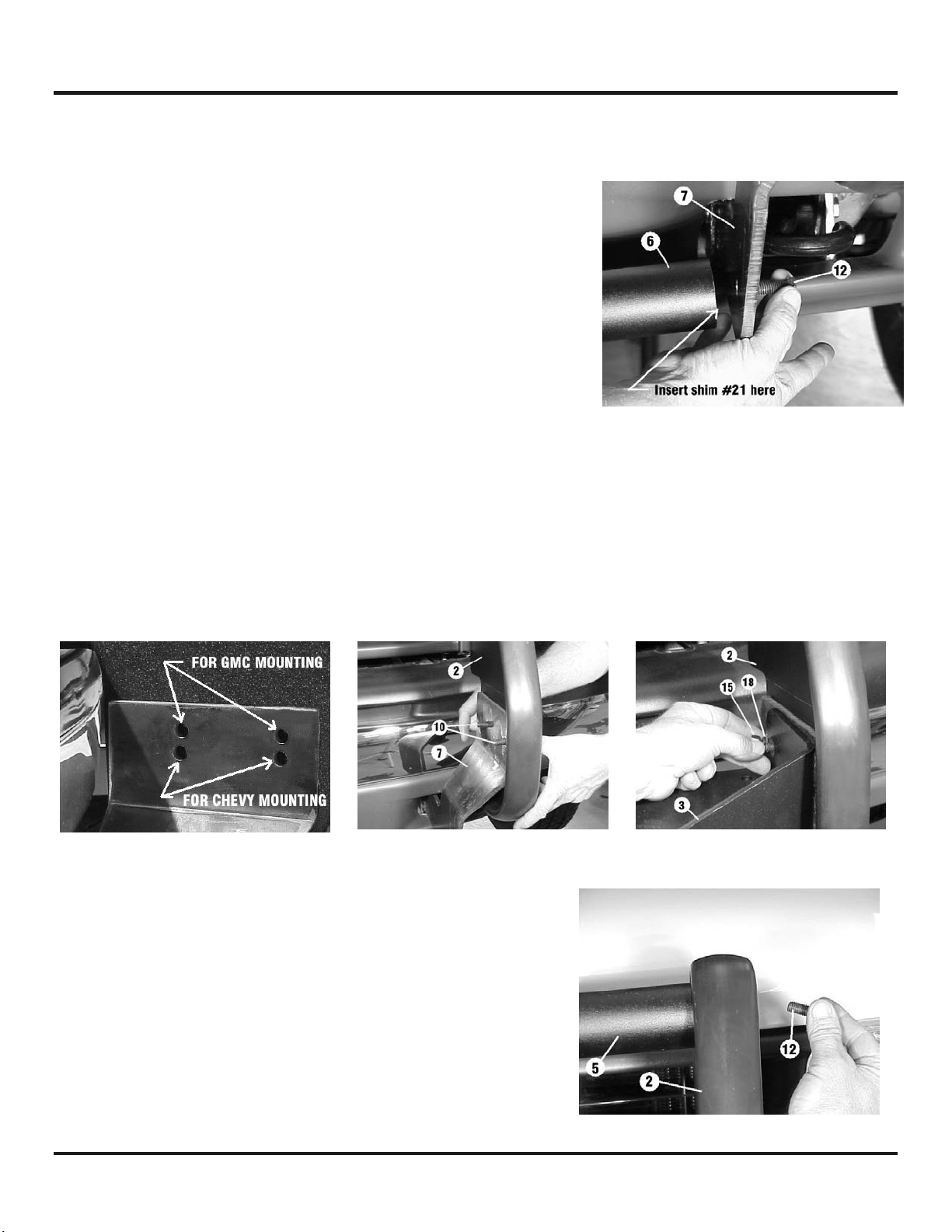
Step 4
Install lower tube assembly #6 between lower brackets #7 & #8.
Insert (1) shim #21 between tube and bracket at each end
(Figure 4). Secure using (1) 3/8-16NC x 1” plated capscrew
#12 through bracket and into threaded hole in each end of tube.
Do not tighten hardware completely.
Step 5
NOTE: YOU WILL NEED ASSISTANCE FOR THIS STEP.
Install left-hand side plate assembly #2. If you are mounting this kit on a Chevy Silverado, use the
bottom set of holes in the bracket assembly. If you are mounting this kit on a GMC Sierra, use the
top set of holes in the bracket (Figure 5). Insert (2) 3/8-16NC x 1-1/2” plated carriage bolts #10
through the holes in side plate #2 and into the appropriate holes in bracket #7. Have someone hold
the side plate in place while you position channel assembly #3. Secure using (1) black lockwasher
#18 and (1) black nut #15 for each carriage bolt. Do not tighten completely. Repeat for the right
hand side plate.
Figure 5
Figure 4
Step 6
Install upper tube assembly #5 between side plates #2.
Insert (1) shim #21 between tube and side plate at each end.
Secure using (1) 3/8-16NC x 1” plated capscrew #12 through
side plate and into threaded hole in each end of tube (Figure
6). TIGHTEN ALL HARDWARE COMPLETELY. Start at the upper
tube assembly and work down to the lower bracket
assemblies tightening all hardware to the appropriate torque
value. (See Torque Value Chart on page 5).
2
Figure 6
KI-913355-0301-C
Page 4

Step 7
Attach left-hand light tube assembly #4 to left-hand side plate #2 (Figure 7). Insert (2) 3/8-16 NC x 1”
plated carriage bolts #11 through light tube assembly and into side plate as shown. Secure using (2)
plated lockwashers #19 and (2) plated nuts #16. Tighten to torque value listed in Torque Value Chart
on page 5. Repeat for right-hand side.
Figure 7
Step 8
Install fairlead as shown below. Note that top holes in channel (Figure 8) align with bottom holes on
roller fairlead. Secure using capscrews, lockwashers, and nuts furnished with winch.
Figure 8
3
KI-913355-0301-C
Page 5

4
KI-913355-0301-C
Page 6

PARTS LIST
Item # Part # Qty. Description
1 Not Used
2 265082 2 Side plate assembly (left & right)
3 395173 1 Winch mounting channel assembly
4 395387 2 Light tube assembly (left & right)
5 395407 1 Upper tube assembly
6 395408 1 Lower tube assembly
7 395412 1 Lower bracket assembly (left)
8 395413 1 Lower bracket assembly (right)
9 Not Used
10 414219 4 Carriage bolt – 3/8-16NC x 1-1/2” long (plated)
11 414227 4 Carriage bolt – 3/8-16NC x 1” long (plated)
12 414314 4 Capscrew – 3/8-16NC x 1” long (plated)
13 415311 6 Bolt – M12 x 1.75 x 50 mm long (plated)
14 Not Used
15 418033 4 Nut – 3/8-16NC (black)
16 418035 4 Nut – 3/8-16NC (plated)
17 Not Used
18 418175 4 Lockwasher – 3/8” med. sect. (black)
19 418177 4 Lockwasher – 3/8” med. sect. (plated)
20 418218 6 Lockwasher – 1/2” med. sect. (plated)
21 488009 4 Shim
22 440138 2 Cable tie
23 690504 1 Loom
TORQUE VALUE CHART
SIZE TORQUE – FT. LBS. TORQUE - Nm
3/8-16 34 46
1/2-13 87 118
12mm 39 53
5
KI-913355-0301-C
Page 7

6
KI-913355-0301-C
 Loading...