

Page 1
INSTALLATION INSTRUCTIONS FOR
GRILLE GUARD KIT #295358 (FOR RE SERIES)
2002 CHEVY SILVERADO/GMC SIERRA 1500HD
1999-2002 CHEVY SILVERADO/GMC SIERRA 2500
2000-2005 CHEVY SUBURBAN/GMC YUKON XL 2500
NOTICE
Ramsey kits are designed for use with Ramsey Winches only.
Use or sales of kits for other winches or applications voids warranty.
WARNING
Ramsey offers mounting kits and winches for various vehicles. In crash tests on a limited number
of automotive manufacturer's vehicles, winches/mounting kits, which have been properly
mounted, have not interfered with air bag operation.
The user/customer, or their installer, must verify that the mounting kit does not interfere with the
factory air bag sensors, which must not be relocated or modified in any way.
The user/customer should follow the vehicle manufacturer's recommendations and those of a
qualified mechanic to determine if the winch/mounting kit might interfere with the air bag
operation. The user/customer should then determine the suitability of a winch/mounting kit on a
particular vehicle.
PLEASE BE ADVISED THAT THE VEHICLE'S AIR BAG SYSTEM MAY NOT OPERATE
PROPERLY IF THE WINCH/MOUNTING KIT IS NOT MOUNTED IN COMPLIANCE WITH THE
VEHICLE MANUFACTURER'S RECOMMENDATIONS.
DO NOT ATTACH TOW HOOK TO ANY PART OF MOUNTING KIT UNLESS INSTRUCTED TO
DO SO.
DO NOT SUBSTITUTE ATTACHING HARDWARE ITEMS (BOLTS, NUTS, OR WASHERS).
READ AND UNDERSTAND WINCH OWNER'S MANUAL BEFORE INSTALLATION AND OPERATION OF WINCH.
SEE WARNING AND CAUTION.
IMPORTANT NOTES!
1. RIGHT AND LEFT HAND DIRECTIONS AS IF SEATED BEHIND STEERING WHEEL.
2. ALL FASTENING HARDWARE MUST BE LOOSELY ASSEMBLED UNTIL DIRECTED TO TIGHTEN.
RAMSEY WINCH COMPANY
P.O. BOX 581510
TULSA, OKLAHOMA 74158
KI-913357-0105-E
Page 2
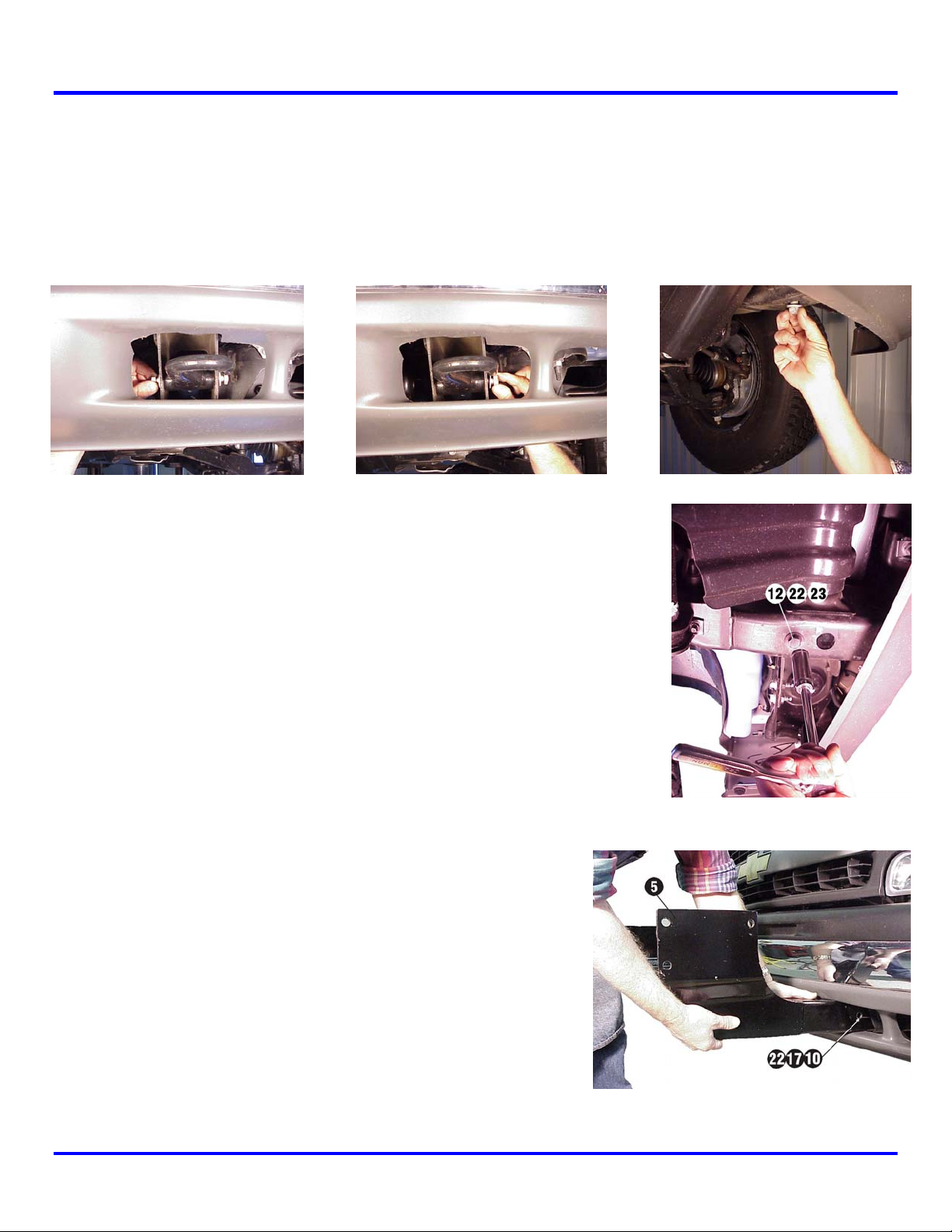
Step 1
Note: It is not necessary to remove or modify the vehicle bumper to install this mounting kit.
Remove the three M12 bolts that secure the vehicle tow hook. They are located on either side and on the bottom of
the tow hook (Figure 1). Remove the tow hook and set it aside.
Figure 1
Step 2
Install left hand bracket #5. Bracket is inserted through the existing
tow hook access in the air dam (Figure 3). Install 1/2-13 NC x 1-1/4
hex head bolt #12, lockwasher #22, & flat washer #23 through
bottom hole in frame (see Figure 2) and into captive nut in bracket #5.
Step 3
Insert 1/2-13NC x 4-1/2” hex bolt #10 through hole in frame (this
is where the tow hook was unbolted in step 1) and through bracket
#5 at location shown in Figure 3. Secure using lockwasher #22 &
nut #17.
Place vehicle tow hook into the front section of bracket #5 (See
Figure 5), and secure using existing tow hook mounting hardware
removed in step 1 at sides and bottom of tow hook.
1
Figure 2
Figure 3
KI-913357-1002-C
Page 3
Step 4
Repeat Step 1 through Step 3 for right hand side of vehicle. Tighten hardware to the appropriate
torque value (See Torque Value Chart on page 5).
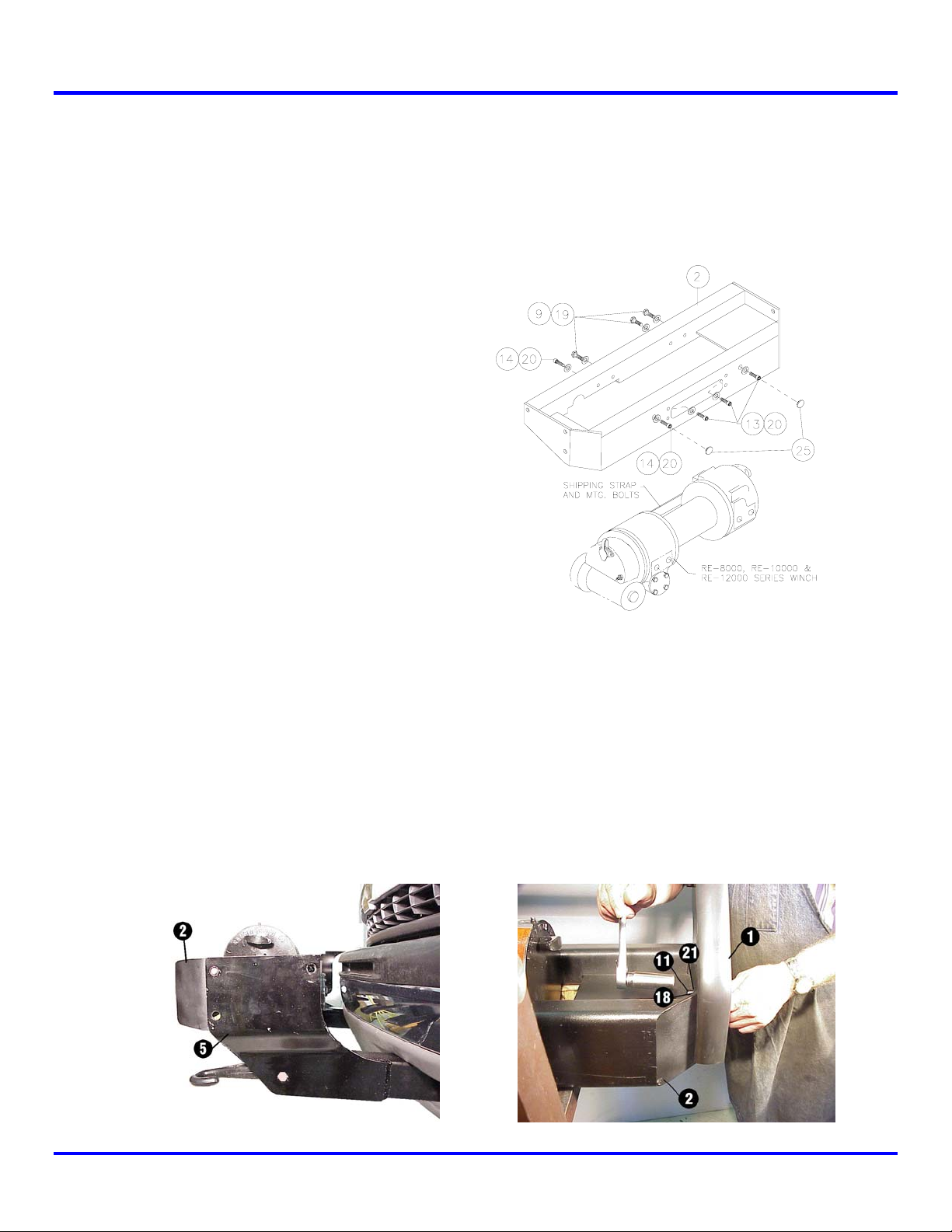
Step 5
Remove shipping strap and mounting bolts from winch assembly and discard. Place frame assembly #2 over top of
winch and secure. Use (3) 3/8-16NC x 1” hex head
capscrews #9 with lockwashers #19 and (1) 3/816NC x 3/4” socket head capscrew #14 with 9/16”
high collar lockwasher #20 to attach winch to rear
angle of frame assembly (Figure 4). DO NOT TIGHTEN.
Attach winch to front angle of frame assembly using (3)
3/8-16NC x 1” socket head capscrews #13 with high
collar lockwashers (9/16 OD) #20 and (1) 3/8-16NC x
3/4” socket head capscrew #14 with 9/16” high collar
lockwasher #20 as shown in Figure 4. Note: The (2)
outer-most capscrews are inserted through holes in
face of mounting frame and threaded into winch. The
(2) inner-most capscrews are placed through fairlead
opening and threaded into winch. Tighten front
hardware to appropriate torque value, then tighten
back hardware (See Torque Value Chart on page
5). Snap hole plugs #25 into outer-most holes in front
of frame assembly.
Figure 4
Step 6
NOTE: YOU WILL NEED ASSISTANCE FOR THIS STEP.
Have someone hold the winch and mounting frame #2 between the left and right brackets. Position
left-hand side plate assembly #1 at the outside of the winch mounting frame (Figure 5). Insert (3) 1/213NC x 1-1/2” carriage bolts #11 through the holes in side plate #1, through frame mounting bracket
#5, and through the mounting frame. Secure using (1) lockwasher #21 and nut #18 for each carriage
bolt. Do not tighten completely. Repeat for the right hand side plate.
Figure 5
2
KI-913357-1002-C
Page 4

Step 7
Install upper tube assembly #3 between side plates #1.
Insert (1) shim #26 between tube and side plate at each
end. Secure using (1) 3/8-16NC x 3/4” hex socket button
head capscrew #15 through side plate and into threaded
hole in each end of tube (Figure 6). Repeat for other tube.
TIGHTEN ALL HARDWARE COMPLETELY. Start at the upper tube
assembly and work down to the lower bracket assemblies
tightening all hardware to the appropriate torque value. (See
Torque Value Chart on page 5).
Figure 6
Step 8
Install fairlead as shown below. Note that top holes in channel (Figure 7) align with bottom holes on
roller fairlead. Secure using capscrews, lockwashers, and nuts furnished with winch.
Figure 7
3
KI-913357-1002-C
Page 5

4
KI-913357-1002-C
Page 6

PARTS LIST
Item # Part # Qty. Description
1 265085 2 Side plate assembly (left & right)
2 395230 1 Winch mounting frame assembly
3 395272 2 Upper tube assembly
4 395415 1 Bracket assembly (right)
5 395416 1 Bracket assembly (left)
6 395417 2 Not Used
7 414220 4 Not Used
8 414320 2 Capscrew – 3/8-16NC x 1-1/4” lg. Gr. 5, F/B
9 414321 3 Bolt – 3/8-16NC x 1” lg. Hex Head, Gr. 5, F/B
10 414519 2 Bolt – 1/2-13NC x 4-1/2” lg. Hex Head, Gr. 5, F/B
11 414560 6 Carriage bolt – 1/2-13NC x 1-1/2” long, Gr. 5, F/B
12 414578 2 Carriage bolt – 1/2-13NC x 1-1/4” long, Hex Head, Gr. 5, Z/P
13 414919 3 Screw – 3/8-16NC x 1” long, Hex Socket Head, F/B
14 414936 2 Capscrew – 3/8-16NC x 3/4” long, Hex Socket Head, F/B
15 414937 4 Capscrew – 3/8-16NC x 3/4” long, Hex Socket Button Head, F/B
16 418033 2 Nut – 3/8-16NC F/B
17 418069 2 Nut – 1/2-13NC Hex, Reg., Z/P
18 418072 6 Nut – 1/2-13NC Hex, Reg., F/B
19 418175 5 Lockwasher – 3/8” med. sect. F/B
20 418188 5 Lockwasher – 3/8” Hi-collar, F/B
21 418216 6 Lockwasher - 1/2” med. sect., F/B
22 418218 4 Lockwasher – 1/2” med. sect. Z/P
23 418223 2 Washer – 1/2 USS, flat, Z/P
24 440138 4 Cable tie
25 472027 2 Plug, 5/8” – plastic, F/B
26 488011 4 Shim
27 690504 1 Loom
28 312525 2 License mounting bracket
29 414036 4 Capscrew 1/4-20NC x 1/2” Hex Head Gr. 5, F/B
30 416279 2 Screw ¼-20NC x 3/4” Hex Head Self Tapping, F/B
31 418020 4 Nut ¼-20NC Hex Reg. F/B
32 418147 6 Lockwasher 1/4 Med. Sect. F/B
TORQUE VALUE CHART
SIZE TORQUE – FT. LBS. TORQUE - Nm
3/8-16 34 46
1/2-13 87 118
M12 60 90
5
KI-913357-1002-C
Page 7

6
KI-913357-1002-C
 Loading...