

Page 1
INSTALLATION INSTRUCTIONS FOR
Y
WRAPAROUND KIT #295356
ON 1999-2004 FORD F250 – F550
WITH RPH 12,000 FRONT MOUNT WINCH # 123305
Ramsey kits are designed for use with Ramsey Winches only.
Use or sales of kits for other winches or applications voids warranty.
NOTICE
WARNING
Ramsey offers mounting kits and winches for various vehicles. In crash tests on a limited number
of automotive manufacturer's vehicles, winches/mounting kits, which have been properly
mounted, have not interfered with air bag operation.
The user/customer, or their installer, must verify that the mounting kit does not interfere with the
factory air bag sensors, which must not be relocated or modified in any way.
The user/customer should follow the vehicle manufacturer's recommendations and those of a
qualified mechanic to determine if the winch/mounting kit might interfere with the air bag
operation. The user/customer should then determine the suitability of a winch/mounting kit on a
particular vehicle.
PLEASE BE ADVISED THAT THE VEHICLE'S AIR BAG SYSTEM MAY NOT OPERATE
PROPERLY IF THE WINCH/MOUNTING KIT IS NOT MOUNTED IN COMPLIANCE WITH THE
VEHICLE MANUFACTURER'S RECOMMENDATIONS.
DO NOT ATTACH TOW HOOK TO ANY PART OF MOUNTING KIT UNLESS INSTRUCTED TO
DO SO.
DO NOT SUBSTITUTE ATTACHING HARDWARE ITEMS (BOLTS, NUTS, OR WASHERS).
READ AND UNDERSTAND WINCH OWNER'S MANUAL BEFORE INSTALLATION AND
OPERATION OF WINCH. SEE WARNINGS, CAUTIONS, AND OPERATION.
IMPORTANT NOTES!
1. RIGHT AND LEFT HAND DIRECTIONS AS IF SEATED BEHIND STEERING WHEEL.
2. ALL FASTENING HARDWARE MUST BE LOOSELY ASSEMBLED UNTIL DIRECTED TO TIGHTEN.
RAMSEY WINCH COMPAN
P.O. BOX 581510
TULSA, OKLAHOMA 74158
KI-913344-0803-D
Page 2
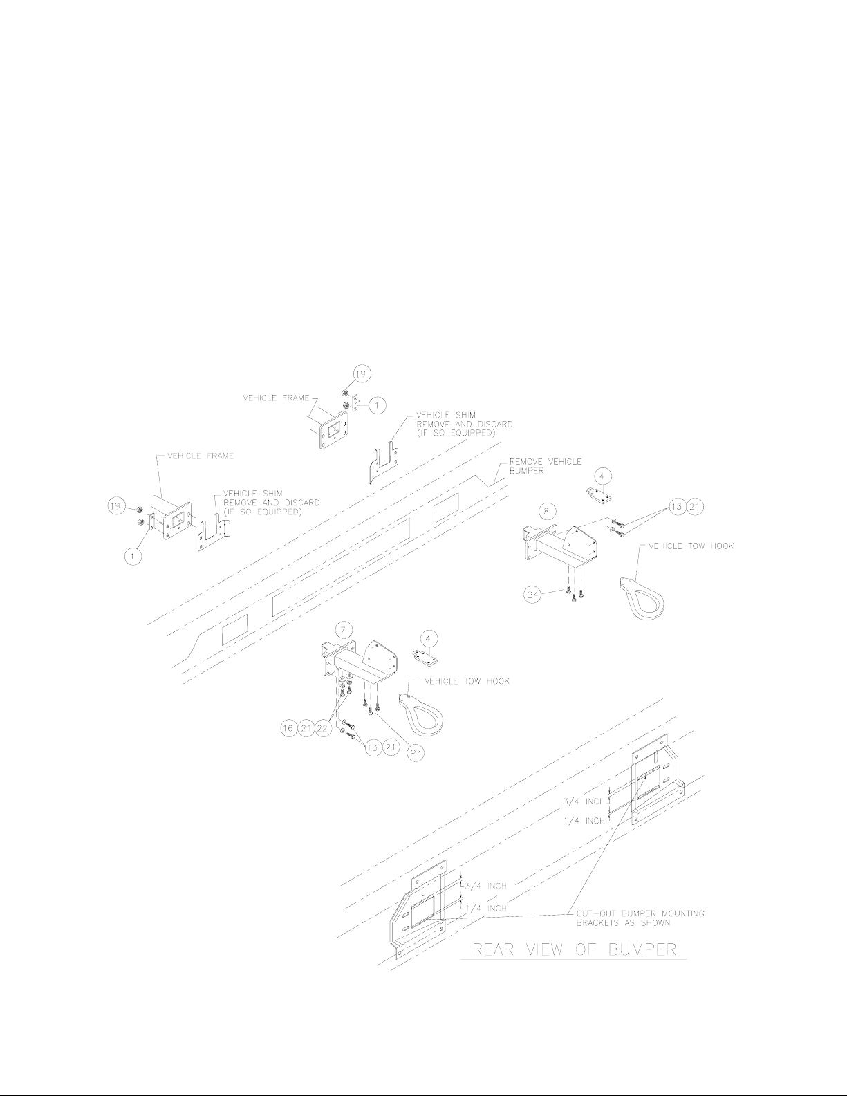
STEP 1
Unfasten plastic splashguard from radiator support bracket. Remove vehicle tow hooks and vehicle
bumper. Remove and discard shims hanging from front of vehicle frame.
Enlarge rectangular cutout in bumper bracket by 1/2" at top and 1/4” at bottom. See REAR VIEW OF
BUMPER below.
Attach nut plate #4 to inside of bracket assembly #7 & #8 using (2) 1/2-13NC x 1-1/4 lg. capscrews
#16 with lockwashers #21, and flatwashers #22, in the two front holes each side.
You will need assistance for this step.
While holding bumper in place, install end of R.H. and L.H. bracket assemblies through bumper and
bumper brackets and into ends of R.H. and L.H. vehicle frame. Secure brackets to front of frame
using (2) 1/2-13NC x 1-1/2 lg. capscrews #13, with lockwashers #21, nuts #19 and nut strips #1, each
side. DO NOT TIGHTEN HARDWARE COMPLETELY.
1
Page 3
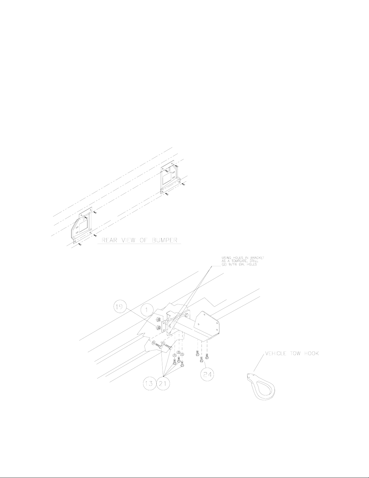
STEP 2
Remove (4) bumper bracket bolts from each side of bumper. This allows bumper to move forward to
provide access to lower bracket bolts. Use (3) 1/2-13NC x 1-1/2 lg. capscrews #13, with lockwashers
#21 through bottom of vehicle frame and into nut plate attached to bracket assemblies, each side.
Tighten hardware to full torque. (See torque value chart, page 6).
Reattach bumper to bumper brackets and tighten all hardware to full torque. Use bracket assembly
#7 & #8 as a template to drill (2) 9/16 DIA. holes through bumper brackets, as shown below. Install
(2) 1/2-13NC x 1-1/2lg. capscrews #13, with lockwashers #21, nuts #19 and nut strips #1, each side.
Reattach vehicle tow hooks to underside of bracket assembly #7 & #8 using M12 x 1.75 x 50mm
capscrews. Discard the existing bolts. Tighten to full torque. (See torque value chart, page 6).
Reattach splashguard.
2
Page 4

STEP 3
Place frame assembly #3 between bracket assemblies #7 & #8 and R.H. & L.H. side plates #2 to the
outsides of bracket assemblies. Use (3) 1/2-13NC x 1-1/2 lg. carriage bolts #15 and (1) 1/2-13NC x
1-1/4 lg. carriage bolt #14, with lockwashers #21, and nuts #19 (each side), as shown, to attach side
plates and brackets to frame assembly. DO NOT TIGHTEN HARDWARE.
Install (1) tube assembly #6 at top between side plates #2, placing shims #23 between side plates
and ends of tube. Secure using (1) 3/8-16 NC X 3/4 lg. hex socket button head capscrew #17 at
each end. Attach light tube assemblies #9 to side plates, as shown. Use (2) 3/8-16NC x 1 lg.
carriage bolts #10, with lockwashers #20 and nuts #18, each side.
3
Page 5

STEP 4
Remove base tie bars from bottom of winch end bearings. Place winch in cavity of frame #3 on top of
mounting plate. Place (2) base tie bars between the rear winch feet and the mounting plate. Place
the other two base tie bars between the front winch feet and the mounting platform. Secure using (8)
1/2-13NC X 1-1/2 lg. hex hd. capscrews inserted through 1/2” lockwashers then through mounting
plate, base tie bars, and into tapped holes in winch feet. Tighten securely. (See torque value chart,
page 6).
Install remaining bottom tube assembly #6 between side plates #2, placing shims #23 between side
plates and ends of tube. Secure using (1) 3/8-16 NC X 3/4 lg. hex socket button head capscrew #17
at each end. Tighten all hardware to proper torque value (see Torque value chart, page 6).
4
Page 6

STEP 5
Place roller fairlead over holes in mounting plate. Install (2) 3/8-16 NC X 1 lg. capscrews #11 through
(2) 3/8” lockwashers #20, then through inside holes in mounting plate and into the threaded holes in
bottom of roller guide. Install (2) 3/8-16 NC X 1-1/2 lg. capscrews #12 through outside holes of
mounting plate and roller guide and secure using (2) 3/8 lockwashers #20, and (2) nuts #18. Tighten
hardware to proper torque value (see Torque value chart, page 6).
SEE PAGE 2 OF WINCH OWNER’S MANUAL FOR CABLE INSTALLATION, PAGE 3 FOR
HYDRAULIC SCHEMATICS, AND PAGE 14 (VIEW A-A) FOR HYDRAULIC LINES INSTALLATION
.
REFER TO WINCH OWNER'S MANUAL FOR PROPER OPERATIONS.
5
Page 7

PARTS LIST FOR KIT #295356 (BLACK)
ITEM NO. QTY. PART NO. DESCRIPTION
1 4 364165 NUT STRIP
2 2 265073 SIDE PLATE R.H. & L.H.-BLACK
3 1 265083 FRAME ASSEMBLY-WINCH MNTG.
4 2 350666 PLATE-NUT
6 2 395272 TUBE ASSEMBLY (BLACK)
7 1 395380 BRACKET ASSEMBLY-R.H.
8 1 395381 BRACKET ASSEMBLY-L.H.
9 2 395386 LIGHT TUBE ASSEMBLY (BLACK)
10 4 414220 CARRIAGE BOLT 3/8-16NC X 1 LG. GR.5 BLACK
11 2 414321 CAPSCREW 3/8-16NC X 1" LG. HX. HD. GR.5 BLACK
12 2 414322 CAPSCREW 3/8-16NC X 1-1/2 LG. HX. HD. GR.5 BLACK
13 14 414551 CAPSCREW 1/2-13NC X 1-1/2 LG. HX. HD. GR.5 BLACK
14 2 414559 CARRIAGE BOLT 1/2-13NC X 1-1/4 LG. GR.5 BLACK
15 6 414560 CARRIAGE BOLT 1/2-13NC X 1-1/2 LG. GR.5 BLACK
16 4 414592 CAPSCREW 1/2-13NC x 1-1/4 LG. HX. HD. GR.5 BLACK
17 4 414937 CAPSCREW 3/8-16NC X 3/4 LG. HX. SOC. BUTTON HD. BLK.
18 6 418033 NUT 3/8-16NC HX. REG.-BLACK
19 16 418072 NUT 1/2-13NC HX. REG.-BLACK
20 8 418175 LOCKWASHER 3/8 MED. SECT.-BLACK
21 26 418216 LOCKWASHER 1/2 MED. SECT.-BLACK
22 4 418229 WASHER 1/2 FLAT
23 4 488011 SHIM-PLASTIC
24 6 415311 CAPSCREW M12 X 1.75 X 50 HX HD GR8.8 Z/P
SIZE TORQUE FT./LB. NM
TORQUE VALUE CHART
3/8-16 39 52
1/2-13 87 118
6
 Loading...