

Page 1
INSTALLATION INSTRUCTIONS
pp
Y
FOR WRAPAROUND KIT #295344
ON 1999-2004 FORD SUPER DUTY F-250/F550
& 2000-2004 FORD EXCURSION
Ramsey kits are designed for use with Ramsey Winches only.
Use or sales of kits for other winches or a
NOTICE
lications voids warranty.
WARNING
Ramsey offers mounting kits and winches for various vehicles. In crash tests on a limited number
of automotive manufacturer's vehicles, winches/mounting kits, which have been properly
mounted, have not interfered with air bag operation.
The user/customer, or their installer, must verify that the mounting kit does not interfere with the
factory air bag sensors, which must not be relocated or modified in any way.
The user/customer should follow the vehicle manufacturer's recommendations and those of a
qualified mechanic to determine if the winch/mounting kit might interfere with the air bag
operation. The user/customer should then determine the suitability of a winch/mounting kit on a
particular vehicle.
PLEASE BE ADVISED THAT THE VEHICLE'S AIR BAG SYSTEM MAY NOT OPERATE
PROPERLY IF THE WINCH/MOUNTING KIT IS NOT MOUNTED IN COMPLIANCE WITH THE
VEHICLE MANUFACTURER'S RECOMMENDATIONS.
DO NOT ATTACH TOW HOOK TO ANY PART OF MOUNTING KIT UNLESS INSTRUCTED TO
DO SO.
DO NOT SUBSTITUTE ATTACHING HARDWARE ITEMS (BOLTS, NUTS, OR WASHERS).
READ AND UNDERSTAND WINCH OWNER'S MANUAL BEFORE INSTALLATION AND OPERATION OF WINCH.
SEE WARNING AND CAUTION.
IMPORTANT NOTES!
1. RIGHT AND LEFT HAND DIRECTIONS AS IF SEATED BEHIND STEERING WHEEL.
2. ALL FASTENING HARDWARE MUST BE LOOSELY ASSEMBLED UNTIL DIRECTED TO TIGHTEN.
RAMSEY WINCH COMPAN
P.O. BOX 581510
TULSA, OKLAHOMA 74158
KI-913336-0204-L
Page 2
STEP 1
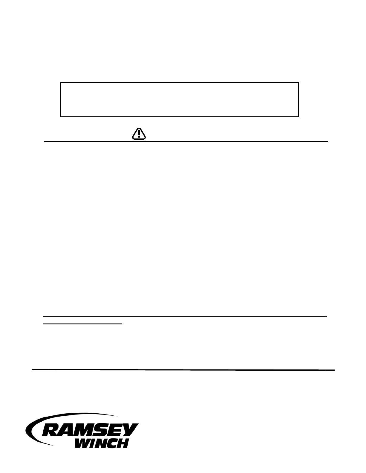
1. Unfasten plastic splashguard from radiator support bracket. Loosen, but do not remove, the
two bolts on the arms of the bumper support bracket as shown in Figure 1. Remove the bolt
attached to the vehicle frame. Repeat for other side of vehicle. Remove tow hooks and
vehicle bumper. Remove and discard shims hanging from front of vehicle frame, if so
equipped.
Figure 1
Figure 2
Figure 3
2. Next remove the two bolts on the left side of the blocker
bar as shown in Figure 2. Remove the three nuts on the
underside of the blocker bar as shown in Figure 3.
Repeat for other side of vehicle and remove blocker bar.
On some models, to remove the blocker bar, remove the
four bolts that hold the blocker bar to the bracket as
shown in Figure 3a.
Figure 3a
1
Page 3
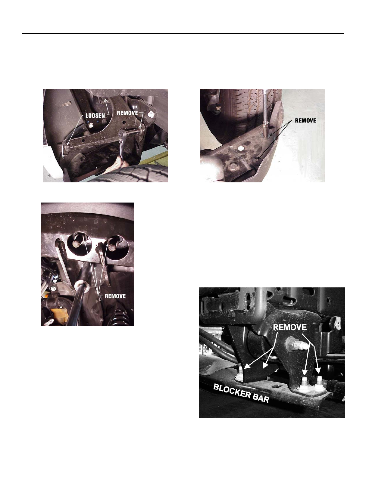
STEP 1
3. Loosen, but do not remove, the two top bolts on the blocker bar mounting bracket as shown in
Figure 4. Loosen, but do not remove, the two bolts on the under side of the blocker bar
mounting bracket. Repeat for other side of vehicle.
Figure 4
Figure 5
2
Page 4

STEP 2
Enlarge rectangular cutout in bumper bracket by 3/4 at top and 1/4” at bottom". See REAR VIEW
OF BUMPER below.
Attach nut plate (item #4) to inside of each bracket assembly (items #7 & #8) using (2) 1/2-13NC x 11/4 lg. capscrews with lockwashers and flatwashers, each side. While holding bumper in place,
install end of R.H. and L.H. bracket assemblies through bumper and bumper brackets and into ends
of R.H. and L.H. vehicle frame. Secure brackets to front of frame using (3) 1/2-13NC x 1-1/2 lg.
capscrews with lockwashers, nuts, and nut strips (item #1), each side. DO NOT TIGHTEN
HARDWARE COMPLETELY.
3
Page 5

STEP 2
Remove shipping strap and mounting bolts from winch assembly and discard. Place frame assembly
(item #5) over top of winch and secure. Use (3) 3/8-16NC x 1" lg. hx.hd. capscrews with lockwashers
and (1) 3/8-16NC x 3/4 lg. soc.hd. capscrew with high collar lockwasher (9/16 O.D.) to attach winch
to rear angle of frame assembly DO NOT TIGHTEN.
Attach winch to front channel of frame assembly, using (3) 3/8-16NC x 1 lg. soc.hd. capscrews with
high collar lockwashers (9/16 O.D.) and (1) 3/8-16NC x 3/4 lg. soc.hd. capscrew with high collar
lockwasher (9/16 O.D.), as shown below. NOTE: The (2) outer-most capscrews are inserted through
holes in face of channel and threaded into winch. The (2) inner-most holes are placed through
channel at fairlead opening and threaded into winch. Tighten front hardware to proper torque
value then tighten back hardware (see TORQUE VALUE CHART). Snap hole plugs (item #31) into
outer-most holes in front of frame assembly.
4
Page 6

STEP 2
Place frame assembly (item #5), including winch, between bracket assemblies (item #7 & #8) and
R.H. & L.H. side plates (items #2) to the outboard sides of bracket assemblies. Use (3) 1/2-13NC x
1-1/2 lg. and (1) 1/2-13NC x 1-1/4 lg. carriage bolts with lockwashers and nuts (each side), as
shown, to attach side plates and brackets to frame assembly. DO NOT TIGHTEN HARDWARE
Install (2) tube assemblies (item #6) between side plates (items #2), placing shims (item #32)
between side plates and ends of tube. Attach light tube assemblies (item #9) to side plates, as
shown. Use (2) 3/8-16NC x 3/4 carriage bolts with lockwashers and nuts, each side.
5
Page 7

STEP 2
Remove bumper bracket bolts from bumper (4) each side. This allows bumper to move forward to
provide access to lower bracket bolts. Use (3) 1/2-13NC x 1-1/2lg. capscrews with lockwashers
through bottom of vehicle frame and into nut and nut strip attached to bracket assemblies, each side.
Tighten all hardware to full torque.
Reattach bumper to bumper brackets and tighten to full torque. Drill (2) 9/16 DIA. holes through
bumper brackets, as shown below. Use bracket assembly (item #5&6) as a template. Install (2) 1/213NC x 1-1/2lg. capscrews with flatwashers, lockwashers and nuts, each side. Reattach vehicle tow
hooks to inside of bracket assembly (item #5&6) using M12 x 1.75 x 65 mm capscrews in place of
the factory hardware. Reattach splash guard. Reattach blocker bar (see step 1). Tighten to full
torque.
6
Page 8

STEP 3
Attach license tag brackets (item #3) to bottom, R.H. side, of channel using (2) 1/4-20NC x 3/4 lg.
self tapping capscrews with lockwashers. Attach tag to brackets using (4) 1/4-20NC x 1/2 hx.hd.
capscrews with lockwashers and nuts. Tighten all hardware to proper torque value (see TORQUE
VALUE CHART).
Place (2) 3/8-16NC x 1-1/4 lg. capscrews through lower-most holes in frame assembly from inside of
channel. Secure fairlead to capscrews using (2) 3/8 lockwashers and nuts. Tighten hardware to
proper torque value (see TORQUE VALUE CHART).
Refer to winch Owner's Manual Installation Instructions for electrical connections. BE SURE
BATTERY CABLES ARE NOT DRAWN TAUT ACROSS ANY SURFACES WHICH COULD
POSSIBLY DAMAGE THEM. Push battery cables into loom #33 and slide loom up cable as close
as possible to winch mounting frame. Secure loom to cable using (1) cable tie #30 at each end of
loom. To improve appearance, wrap ends of loom with black electrical tape.
Plug remote switch into receptacle of black solenoid cover of winch. Run winch forward and reverse
to check connections. Snap appropriate "IN" and "OUT" disc into proper thumb cavity, after
determining winch operating direction. DO NOT LEAVE SWITCH PLUGGED IN WHEN WINCH IS
NOT IN USE.
Place end of wire rope through fairlead and attach clevis hook. Use clevis pin and cotter pin
(furnished with winch).
REFER TO WINCH OWNER'S MANUAL FOR SAFE OPERATIONS.
7
Page 9

PARTS LIST FOR KIT #295344 (BLACK)
ITEM NO. QTY. PART NUMBER DESCRIPTION
1 4 364165 NUT STRIP
2 2 265073 SIDE PLATE R.H. & L.H.-BLACK
3 2 312525 BRACKET-LICENSE
4 2 350666 PLATE-NUT
5 1 395230 FRAME ASSEMBLY-WINCH MTG
6 2 395272 TUBE ASSEMBLY (BLACK)
7 1 395380 BRACKET ASSEMBLY-R.H.
8 1 395381 BRACKET ASSEMBLY-L.H.
9 2 395386 LIGHT TUBE ASSEMBLY (BLACK)
10 4 414036 CAPSCREW 1/4-20NC X 1/2 LG. HX.HD. GR.5 BLACK
11 4 414220 CARRIAGE BOLT 3/8-16NC X 1 LG. GR.5 BLACK
12 2 414320 CAPSCREW 3/8-16NC X 1-1/4 LG. HX.HD. GR.5 BLACK
13 3 414321 CAPSCREW 3/8-16NC X 1 LG. HX.HD. GR.5 BLACK
14 14 414551 CAPSCREW 1/2-13NC X 1-1/2 LG. HX.HD. GR.5 BLACK
15 2 414559 CARRIAGE BOLT 1/2-13NC X 1-1/4 LG. GR.5 BLACK
16 6 414560 CARRIAGE BOLT 1/2-13NC X 1-1/2 LG. GR.5 BLACK
17 4 414578 CAPSCREW 1/2-13NC X 1-1/4 LG HX.HD. GR.5 PLATED
18 3 414919 CAPSCREW 3/8-16NC X 1 LG. HX.SOC.HD. GR.5 BLACK
19 2 414936 CAPSCREW 3/8-16NC X 3/4 LG. HX.SOC.HD. BLACK
20 4 414937 CAPSCREW 3/8-16NC X 3/4 LG. HX.SOC.BUTTON HD. BLK.
21 2 416279 SCREW 1/4-20NC X 3/4 LG. HX.HD. SELF-TAPPING, BLACK
22 4 418020 NUT 1/4-20NC HX. REG. BLACK
23 6 418033 NUT 3/8-16NC HX. REG.-BLACK
24 16 418072 NUT 1/2-13NC HX. REG.-BLACK
25 6 418147 LOCKWASHER 1/4 MED.SECT. BLACK
26 9 418175 LOCKWASHER 3/8 MED.SECT.-BLACK
27 5 418188 LOCKWASHER 3/8, HI-COLLAR
28 26 418216 LOCKWASHER 1/2 MED.SECT.-BLACK
29 4 418229 WASHER 1/2 FLAT
30 4 440138 CABLE TIES
31 2 472027 PLUG
32 4 488011 SHIM-PLASTIC
33 1 690504 LOOM
34 6 415311 CAPSCREW M12 X 1.75 X 50 MM HX HD GR8.8 Z/P
TORQUE VALUE CHART
SIZE TORQUE
FT./LB. NM
1/4-20 5 7
3/8-16 34 46
1/2-13 50 7
12mm 39 54
5
8
 Loading...