

Page 1
INSTALLATION INSTRUCTIONS
Y
FOR GRILLE GUARD
KIT #295342 (BLACK) & KIT #295343 (CHROME)
ON 1999-2004 FORD EXCURSION / SUPER-DUTY TRUCKS
Ramsey kits are designed for use with Ramsey Winches only.
Use or sales of kits for other winches or applications voids warranty.
NOTICE
WARNING
Ramsey offers mounting kits and winches for various vehicles. In crash tests on a limited number
of automotive manufacturer's vehicles, winches/mounting kits, which have been properly
mounted, have not interfered with air bag operation.
The user/customer, or their installer, must verify that the mounting kit does not interfere with the
factory air bag sensors, which must not be relocated or modified in any way.
The user/customer should follow the vehicle manufacturer's recommendations and those of a
qualified mechanic to determine if the winch/mounting kit might interfere with the air bag
operation. The user/customer should then determine the suitability of a winch/mounting kit on a
particular vehicle.
PLEASE BE ADVISED THAT THE VEHICLE'S AIR BAG SYSTEM MAY NOT OPERATE
PROPERLY IF THE WINCH/MOUNTING KIT IS NOT MOUNTED IN COMPLIANCE WITH THE
VEHICLE MANUFACTURER'S RECOMMENDATIONS.
DO NOT ATTACH TOW HOOK TO ANY PART OF MOUNTING KIT UNLESS INSTRUCTED TO
DO SO.
DO NOT SUBSTITUTE ATTACHING HARDWARE ITEMS (BOLTS, NUTS, OR WASHERS).
READ AND UNDERSTAND WINCH OWNER'S MANUAL BEFORE INSTALLATION AND OPERATION OF WINCH.
SEE WARNING AND CAUTION.
IMPORTANT NOTES!
1. RIGHT AND LEFT HAND DIRECTIONS AS IF SEATED BEHIND STEERING WHEEL.
2. ALL FASTENING HARDWARE MUST BE LOOSELY ASSEMBLED UNTIL DIRECTED TO TIGHTEN.
RAMSEY WINCH COMPAN
P.O. BOX 581510
TULSA, OKLAHOMA 74158
KI-913335-0704-H
Page 2
STEP 1
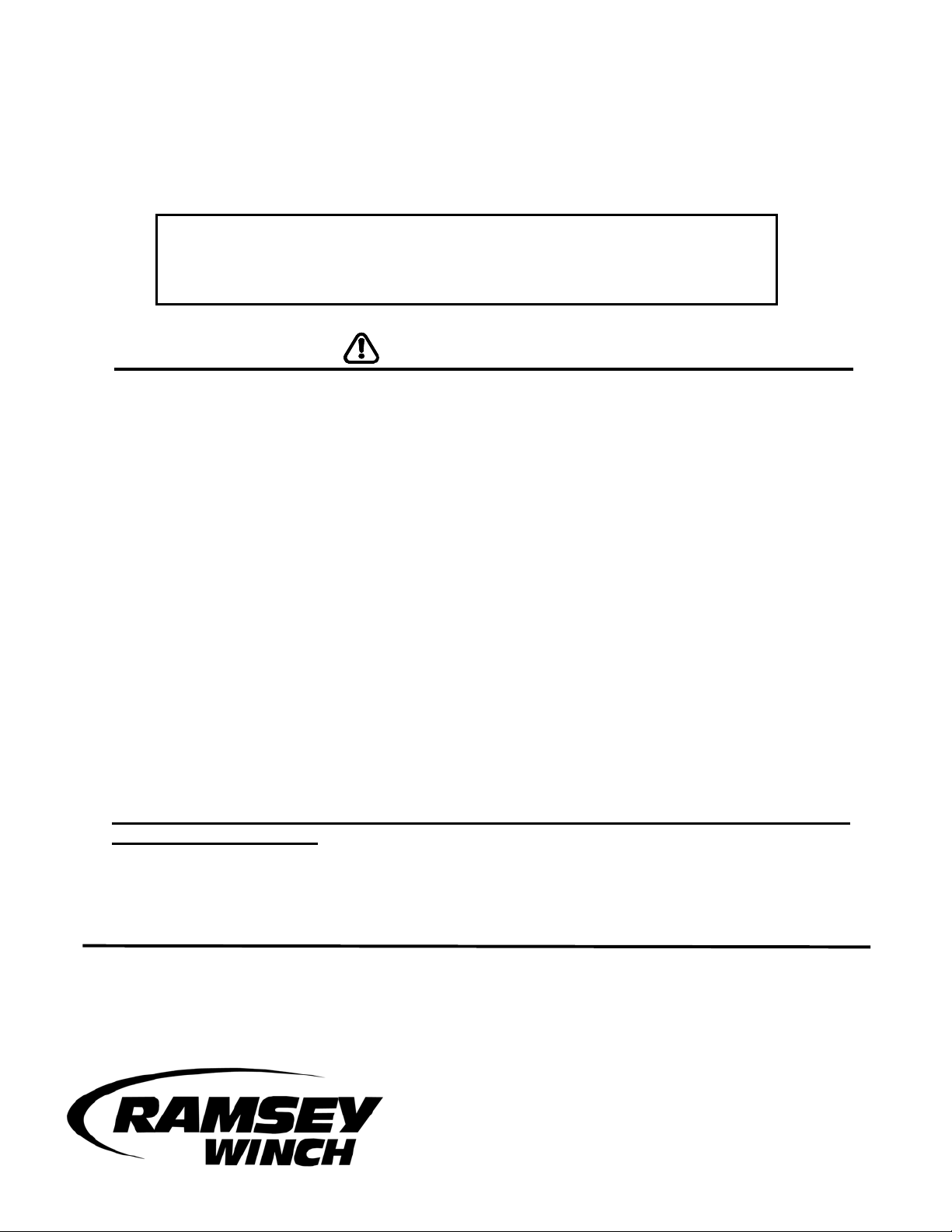
1. Unfasten plastic splashguard from radiator support bracket. Loosen, but do not remove, the
two bolts on the arms of the bumper support bracket as shown in Figure 1. Remove the bolt
attached to the vehicle frame. Repeat for other side of vehicle. Remove tow hooks and
vehicle bumper. Remove and discard shims hanging from front of vehicle frame, if so
equipped.
Figure 1
Figure 2
Figure 3
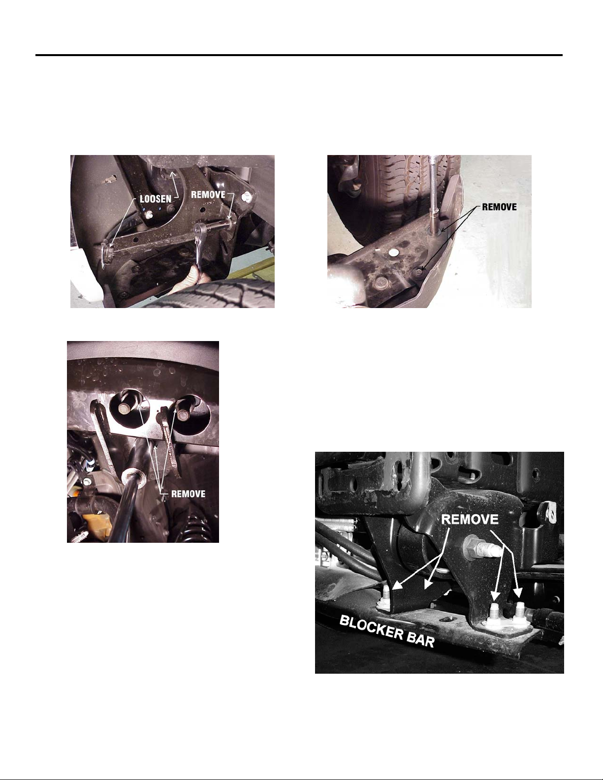
2. Next remove the two bolts on the left side of the blocker
bar as shown in Figure 2. Remove the three nuts on the
underside of the blocker bar as shown in Figure 3.
Repeat for other side of vehicle and remove blocker bar.
On some models, to remove the blocker bar, remove the
four bolts that hold the blocker bar to the bracket as
shown in Figure 3a.
Figure 3a
1
Page 3
STEP 1
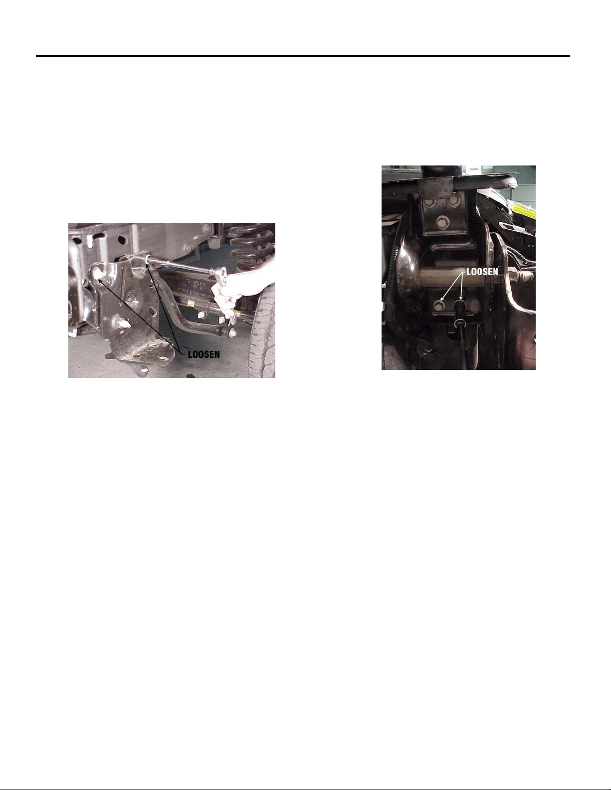
3. Loosen, but do not remove, the two top bolts on the blocker bar mounting bracket as shown in
Figure 4. Loosen, but do not remove, the two bolts on the under side of the blocker bar
mounting bracket. Repeat for other side of vehicle.
Figure 4
Figure 5
2
Page 4

STEP 2
Install rear (1) bolt item # 11,15,13 each side of frame and tighten to full torque. Enlarge rectangular
cutout in bumper bracket by 3/4" at top and 1/4” at bottom, as shown below in REAR VIEW OF
BUMPER.
Attach nut plate (item #2) to inside of each bracket assembly (items #5 & 6) using (2) 1/2-13NC x 11/4 lg. capscrews with lockwashers and flatwashers, each side. While holding bumper in place,
install end of R.H. and L.H. bracket assemblies through bumper and bumper brackets and into ends
of vehicle frame. Make sure that slotted mounting holes on R.H. and L.H. brackets are to the outside.
Secure brackets to front of frame using (2) 1/2-13NC x 1-1/2 lg. capscrews with flatwashers,
lockwashers, and nuts each side. DO NOT TIGHTEN HARDWARE COMPLETELY.
3
Page 5

STEP 2
Place channel (item #3) between R.H. and L.H. bracket assemblies (item #5 & #6). Secure side
plates (item #1) to outside of lower R.H. & L.H. brackets (item #5 & #6) and ends of channel. Use (2)
3/8-16NC x 1-1/4 lg. carriage bolts with lockwashers and nuts (each side).
Attach lower end of side plates (item #1) to outside of R.H. & L.H. brackets (item #5 & #6) use (1)
3/8-16NC x 1 lg. hx.hd. capscrew with lockwasher and nut (each side).
DO NOT TIGHTEN HARDWARE.
Attach tube assembly (item #4) between side plates, with shims (item #18), as shown, using 3/816NC x 3/4 lg. hx.hd. capscrews. Squarely align kit with front of vehicle.
TIGHTEN ALL HARDWARE TO PROPER TORQUE VALUE (See Torque Value Chart, page 5).
4
Page 6

STEP 2
Remove bumper bracket bolts from bumper (4) each side. This allows bumper to move forward to
provide access to lower bracket bolts. Use (2) 1/2-13NC x 1-1/2 lg. capscrews with lockwashers
through bottom of vehicle frame and into nut plate attached to bracket assemblies, each side.
Tighten all hardware to full torque.
Reattach bumper to bumper brackets and tighten to full torque. Drill (2) 9/16 dia. holes through
bumper brackets, as shown below. Use bracket assembly (item #5&6) as a template. Install (2) 1/213NC x 1-1/2 lg. capscrews with flatwashers, lockwashers and nuts, each side. Reattach vehicle tow
hooks to inside of bracket assembly (item #5&6) using (3) M12x1.75x65mm capscrews in place of
factory hardware. Reattach splashguard. Reattach blocker bar (see step 1). Tighten to full torque.
Winch frame omitted for clarity
5
Page 7

STEP 3
FOR PRO-PLUS 9000 WINCH:
Refer to INSTALLATION and ELECTRICAL CONNECTIONS section of winch owner's manual for
installation of fairlead, winch and electrical hookup.
READ, UNDERSTAND AND FOLLOW WINCH OWNER'S MANUAL FOR SAFE OPERATIONS.
6
Page 8

PARTS LIST FOR KIT #295342 (BLACK) & #295343 (CHROME)
ITEM NO. QTY. PART NUMBER DESCRIPTION
1 2 265075 SIDE PLATE R.H. & L.H.-BLACK
2 265076 SIDE PLATE R.H. & L.H.-CHROME
2 2 350658 NUT PLATE
3 1 395170 CHANNEL ASSEMBLY-WINCH MTG.
4 1 395272 TUBE ASSEMBLY (BLACK)
1 395273 TUBE ASSEMBLY (CHROME)
5 1 395384 BRACKET ASSEMBLY-R.H.
6 1 395385 BRACKET ASSEMBLY-L.H.
7 2 414220 CARRIAGE BOLT 3/8-16NC X 1 GR.5 BLACK
2 414227 CARRIAGE BOLT 3/8-16NC X 1 GR.5 PLATED
8 4 414221 CARRIAGE BOLT 3/8-16NC X 1-1/4 GR.5 BLACK
4 414218 CARRIAGE BOLT 3/8-16NC X 1-1/4 GR.5 PLATED
9 2 414937 CAPSCREW 3/8-16NC X 3/4 LG. HX. SOC. BUTTON HD.BLK
2 414938
10 12 414551 CAPSCREW 1/2-13NC X 1-1/2 LG HX.HD. GR.5 BLACK
11 6 414578 CAPSCREW 1/2-13NC X 1-1/4 LG HX.HD. GR.5 PLATED
12 6 418033 NUT 3/8-16NC HX. REG.-BLACK
13 10 418069 NUT 1/2-13NC HX. REG. Z.P.
14 6 418175 LOCKWASHER 3/8 MED.SECT.-BLACK
15 18 418218 LOCKWASHER 1/2 MED.SECT.-PLATED
16 12 418229 WASHER 1/2 FLAT
17 4 440138 CABLE TIES
18 2 488011 SHIM-PLASTIC
19 24" 690504 LOOM
20 6 415311 CAPSCREW M12 X 1.75 X 50 MM HX HD GR10,9
CAPSCREW 3/8-16NC X 3/4 LG. HX. SOC. BUTTON HD.PLTD
TORQUE VALUE CHART
TORQUE
SIZE FT./LB. NM
3/8-16 34 46
1/2-13 50 7
12MM 39 54
5
7
 Loading...