

Page 1
INSTALLATION INSTRUCTIONS FOR
WRAPAROUND
KIT #295252 (CHROME) & KIT #295253 (BLACK)
ON FULLSIZE DODGE TRUCKS
NOTICE
Ramsey kits are designed for use with Ramsey Winches only.
Use or sales of kits for other winches or applications voids warranty.
WARNING
Ramsey offers mounting kits and winches for various vehicles. In crash tests on a limited number
of automotive manufacturer's vehicles, winches/mounting kits, which have been properly
mounted, have not interfered with air bag operation.
The user/customer, or their installer, must verify that the mounting kit does not interfere with the
factory air bag sensors, which must not be relocated or modified in any way.
The user/customer should follow the vehicle manufacturer's recommendations and those of a
qualified mechanic to determine if the winch/mounting kit might interfere with the air bag
operation. The user/customer should then determine the suitability of a winch/mounting kit on a
particular vehicle.
PLEASE BE ADVISED THAT THE VEHICLE'S AIR BAG SYSTEM MAY NOT OPERATE
PROPERLY IF THE WINCH/MOUNTING KIT IS NOT MOUNTED IN COMPLIANCE WITH THE
VEHICLE MANUFACTURER'S RECOMMENDATIONS.
DO NOT ATTACH TOW HOOK TO ANY PART OF MOUNTING KIT UNLESS INSTRUCTED TO
DO SO.
DO NOT SUBSTITUTE ATTACHING HARDWARE ITEMS (BOLTS, NUTS, OR WASHERS).
READ AND UNDERSTAND WINCH OWNER'S MANUAL BEFORE INSTALLATION AND
OPERATION OF WINCH. SEE WARNING AND CAUTION.
IMPORTANT NOTES!
1. RIGHT AND LEFT HAND DIRECTIONS AS IF SEATED BEHIND STEERING WHEEL.
2. ALL FASTENING HARDWARE MUST BE LOOSELY ASSEMBLED UNTIL DIRECTED TO TIGHTEN.
RAMSEY WINCH COMPANY
P.O. BOX 581510
TULSA, OKLAHOMA 74158
KI-913275-0999-G
Page 2
STEP 1
1. Vehicles equipped with factory tow hooks do not use spacer plate #31 (Refer to Step 2, Paragraph 4). If
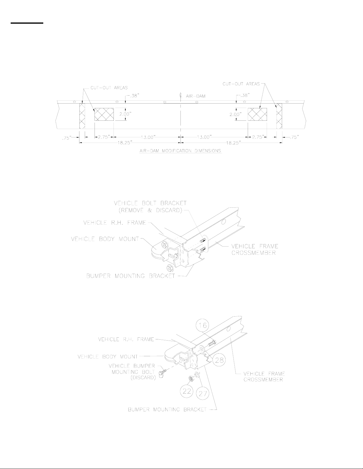
vehicle is equipped with a lower air-dam, it must be modified to the diagram below or removed. The
notches and holes must be added for clearance of brackets #2, & #3 and braces #4 & #5 installed in a
later step.
NOTE: It is not necessary to remove the air-dam to add the notches and holes. It is easier to make the
cutouts with the air dam in place.
NOTE: IF YOU ARE INSTALLING A PRO-8000 OR PRO-9000 SERIES WINCH ON A 1998 OR 1999
VEHICLE ONLY, PLEASE GO TO PAGE 8 OF INSTRUCTIONS.
2. Remove vehicle bolt bracket from R.H. side of vehicle frame and discard bracket and nuts.
3. Install (1) 7/16-14NC x 1-1/2 lg. capscrew #16 with flatwasher #28, lockwasher #27, and nut #22 in
upper hole to hold vehicle bumper in place. Tighten capscrew to proper torque value (see TORQUE
VALUE CHART). Next, remove vehicle bumper mounting bolt and nut from vehicle frame and discard.
4. Repeat for L.H. side of vehicle.
1
KI-913275-0999-G
Page 3
5. NOTE: INSTRUCTIONS ON THIS PAGE APPLY ONLY TO PRO-8000 OR PRO-9000 SERIES
WINCHES ON A 1994-1997 VEHICLE. For all other winches, go to page 3.
a. If you are mounting a Pro-8000 or Pro-9000 series winch on a 1998 or 1999 vehicle, please use the
alternate instructions on page 8.
b. If you are mounting a Pro-8000 or Pro-9000 series winch on a 1994–1997 vehicle use the instructions
on this page.
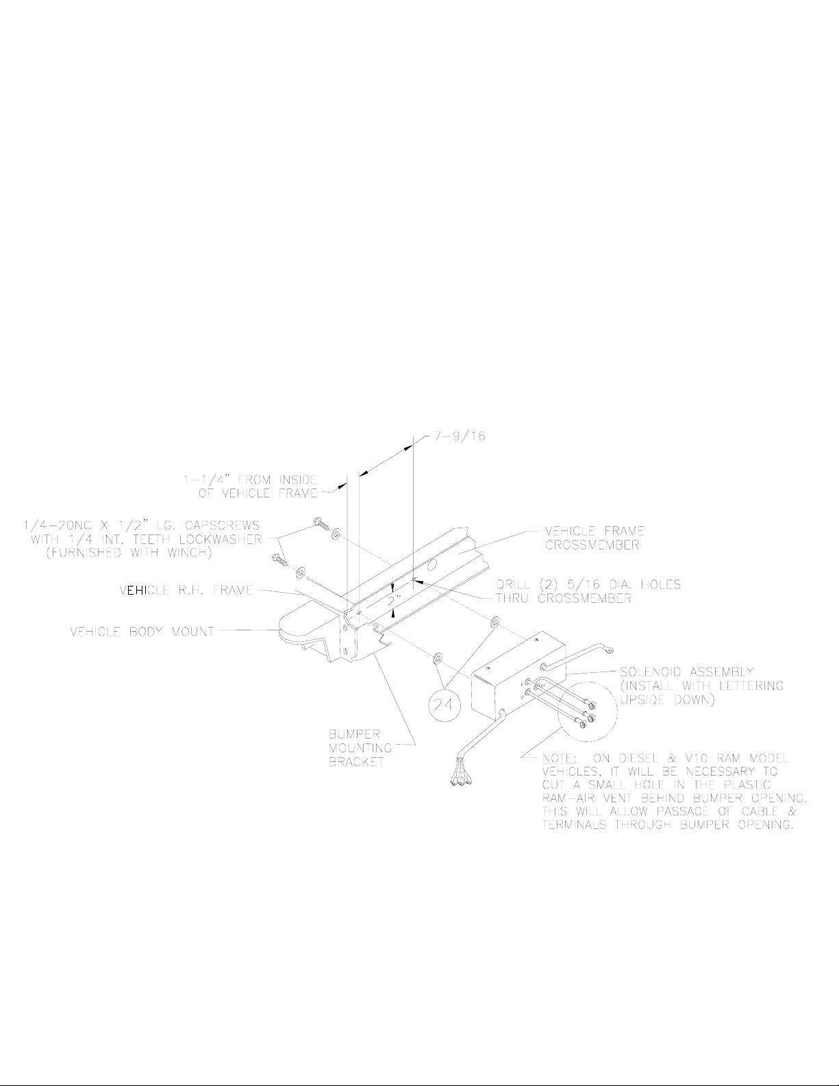
6. Mount solenoid assembly to the front side of the vehicle frame crossmember as follows:
a. Mark and centerpunch crossmember on the back (See diagram below for dimensions).
b. Drill (2) 5/16” dia. holes through the crossmember at the location shown below.
c. Attach solenoid assembly to crossmember using (2) ¼-20NC x ½” hex head capscrews with
lockwashers (furnished with winch).
d. Insert capscrews through lockwashers, then through back of vehicle crossmember, then through
flatwashers #24, and thread into captive nuts in bottom of solenoid assembly.
e. Tighten hardware securely.
NOTE: PLEASE READ INSTRUCTIONS ABOUT VEHICLE FRAME MOUNTING HOLE
CHANGE ON LAST 2 PAGES BEFORE YOU CONTINUE!
2
KI-913275-0999-G
Page 4
STEP 2
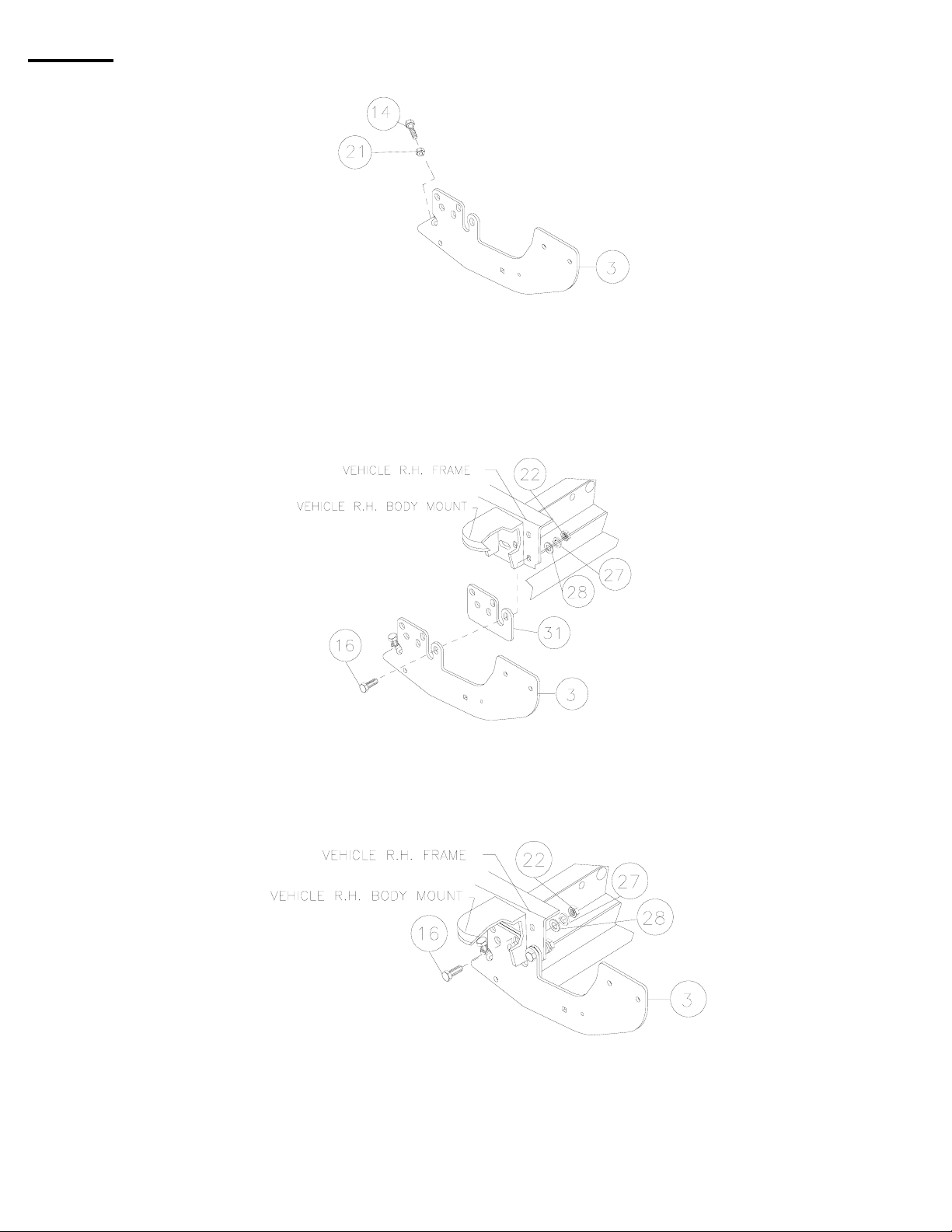
2. Thread (1) 3/8-16NC x 1-1/2 capscrew #14 through lock nut #21 and through nut welded to bottom of
bracket #3.
3. If vehicle is not equipped with tow hooks, this kit requires spacer plate #31 to be used.
4. Mount R.H. bracket #3 as shown, adding spacer plate #31 (if required). Using (1) 7/16-14NC x 1-1/2 lg.
hx. hd. capscrew #16, insert through front hole of bracket, then through spacer plate #31 (if required) or
tow hook and then through bumper mounting bracket and frame. Attach with flatwasher #28, lockwasher
#27 and nut #22 as shown. DO NOT TIGHTEN.
5. For the middle hole, insert (1) 7/16-14NC x 1-1/2 lg. hx hd capscrew #16, insert through bracket #3, then
through spacer plate #31 (if required) or tow hook and then through bumper mounting bracket and
frame. Attach with flatwasher #28, lockwasher #27 and nut #22 as shown. DO NOT TIGHTEN.
3
KI-913275-0999-G
Page 5

6. Place 1/2” nut extender #10 through hole in vehicle frame just below bumper strut. NOTE: It is necessary
to temporarily loosen strut-mounting hardware and shift strut clear until extender is attached. Install (1)
1/20--13NC x 1-1/2" lg. capscrew #17 with lockwasher #29 through bracket #3, as shown in VIEW A-A,
and thread into nut of nut extender (each side).
7. Shift vehicle bumper strut back into place and reinstall bumper strut mounting hardware.
Repeat 2-7 for L.H. bracket
After brackets are mounted to vehicle frame, tighten adjuster screw firmly against bottom of vehicle frame,
and tighten lock nuts against brackets.
STEP 3
1. You will need assistance for this step.
2. Have someone hold the winch mounting channel #6 between brackets #2 & #3.
3. Position R.H. side plate #7 to outside of bracket #3 as shown below.
4. Insert (2) 3/8-16NC x 1-1/2 lg. carriage bolts #13 through side plates, mounting bracket and winch
mounting channel as shown below. Secure using 3/8” lockwasher #26 and 3/8” nut #20 for each
carriage bolt.
5. Repeat for L.H. side.
6. Finally, insert 3/8-16NC x 1-1/2 lg carriage bolt #13 through rear hole of side plate and into mounting
bracket as shown below. Secure using 3/8” lockwasher #26 and 3/8” nut #20.
7. Repeat for L.H. side.
DO NOT TIGHTEN HARDWARE
4
KI-913275-0999-G
Page 6

STEP 4
1. Install lower grille tube #8 between side plates #7, placing shims #32 between side plates and ends of tubes. Use 3/8-16NC x
3/4 lg. button hd. capscrews #18 to secure each end of tube to side plates. TIGHTEN HARDWARE SECURELY.
2. Install upper grille tube #8 between side plates #7, placing shims #32 between side plates and ends of tubes. Use 3/8-16NC x
3/4 lg. button hd. capscrews #18 to secure each end of tube to side plates. TIGHTEN HARDWARE SECURELY
3. Attach light tube #9 to side plate as shown. Use (2) 3/8-16NC x 1” carriage bolts #12, with lock washers #26, and nuts #20.
Note: On chrome kit #295253 use plated hardware at this location.
3. Secure fairlead to front of winch mounting channel as shown below using capscrews, lockwashers, and nuts furnished with
winch.
4. Attach license tag brackets #1 to bottom, L.H. side of mounting frame using (2) 1/4-20NC x 3/4 lg. capscrews #11, and
flatwashers #25. Insert capscrews through flatwashers, license-mounting bracket, then through bottom of mounting channel
as shown below. Secure using lockwasher #23 and nut #19.
5
KI-913275-0999-G
Page 7

STEP 5
2. Attach R.H. & L.H. brace #4& #5 to bottom of winch mounting channel #6, as shown below. Use (1) 3/8-16NC X
1-1/2” capscrew #14 each side. Insert capscrew through flatwasher (included with winch), brace, winch mounting
channel, and thread into front feet of winch as shown below.
3. Secure back feet of winch using remaining winch mounting hardware furnished with winch.
4. Attach remaining end of braces to brackets #2 & #3 using (1) 3/8-16NC x 1 lg. hx.hd. capscrew #15 with
lockwasher #26 and nut #20, (each side) as shown below .
5. Square mounting frame, side plates and brackets with front of vehicle by tightening adjuster screw until kit is level
(refer to VIEW A-A, pg. 3). Tighten lock nuts #21 against brackets
1. Tighten all hardware to proper torque value (see TORQUE VALUE CHART).
4. Refer to winch Owner's Manual Installation Instructions for electrical connections.
a. Route free end of red and black battery cables up to battery and secure to terminals using spacers #33, as shown
below.
b. BE SURE BATTERY CABLES ARE NOT DRAWN TAUT ACROSS ANY SURFACES WHICH COULD POSSIBLY
DAMAGE THEM. Use cable ties #30 and loom #34 to secure cable and wires to a location of the installer's
discretion, behind vehicle grille.
c. Plug remote switch into receptacle of black solenoid cover of winch. Run winch forward and reverse to check
connections. Snap appropriate "IN" and "OUT" disc into proper thumb cavity, after determining winch-operating
direction. DO NOT LEAVE SWITCH PLUGGED IN WHEN WINCH IS NOT IN USE.
5. Place end of wire rope through fairlead and attach clevis hook. Use clevis pin and cotter pin (furnished with winch).
REFER TO WINCH OWNER'S MANUAL FOR SAFE OPERATIONS.
6
KI-913275-0999-G
Page 8

PARTS LIST FOR KIT #295252 (CHROME) & #295253 (BLACK)
ITEM #
1 2 312332 BRACKET-LICENSE MTG.
2 1 395164 BRACKET ASSEMBLY-R.H.
3 1 395165 BRACKET ASSEMBLY-L.H.
4 1 395166 BRACE-R.H.
5 1 395167 BRACE-L.H.
6 1 395170 CHANNEL ASSEMBLY-WINCH MTG.
7 2 395270 SIDE PLATE ASSEMBLY-R.H. & L.H. (BLACK)
2 395271 SIDE PLATE ASSEMBLY-R.H. & L.H. (CHROME)
8 2 395272 TUBE ASSEMBLY (BLACK)
2 395273 TUBE ASSEMBLY (CHROME)
9 2 395280 LIGHT TUBE (BLACK)
2 395281 LIGHT TUBE (CHROME)
10 2 408269 NUT EXTENDER - 1/2"
11 2 414048 CAPSCREW 1/4-20NC X 3/4 LG. HX.HD. BLACK
12 4 414220 CARRIAGE BOLT 3/8-16NC X 1 LG. GR.5 BLACK
4 414227 CARRIAGE BOLT 3/8-16NC X 1 LG. GR.5 PLATED
13 6 414222 CARRIAGE BOLT 3/8-16NC X 1-1/2 GR.5 BLACK
6 414219 CARRIAGE BOLT 3/8-16NC X 1-1/2 GR.5 PLATED
14 4 414292 CAPSCREW 3/8-16NC X 1-1/2 GR.8 BLACK
15 2 414321 CAPSCREW 3/8-16NC X 1 LG. HX.HD.GR.5 BLACK
16 6 414479 CAPSCREW 7/16-14NCX1-1/2LG.HX.HD.GR.5 BLACK
17 2 414548 CAPSCREW 1/2-13NC X 1-1/2 LG. HX. HD. GR 5 PLATED
18 4 414937 CAPSCREW 3/8-16NC X 3/4 LG. HX. BUTTON HD. BLACK
4 414938 CAPSCREW 3/8-16NC X 3/4 LG. HX. BUTTON HD. PLATED
19 2 418020 NUT 1/4-20NC HX. REG. BLACK
20 12 418033 NUT 3/8-16NC HX. REG. BLACK
4 418035 NUT 3/8-16NC HX. REG. PLATED
21 2 418044 NUT-LOCK 3/8-16NC PLATED
22 6 418047 NUT 7/16-14NC HX. REG. BLACK
23 2 418147 LOCKWASHER 1/4 MED.SECT. BLACK
24 2 418153 WASHER 1/4 SAE FLAT PLATED
25 2 418158 WASHER-1/4 SAE FLAT, BLACK
26 12 418175 LOCKWASHER 3/8 MED.SECT. BLACK
4 418177 LOCKWASHER 3/8 MED.SECT. PLATED
27 6 418196 LOCKWASHER 7/16 MED.SECT. BLACK
28 6 418208 WASHER 7/16 USS FLAT, BLACK
29 2 418218 LOCKWASHER ½ MED. SECT. PLATED
30 4 440138 CABLE TIES
31 2 474087 SPACER PLATE
32 4 488011 SHIM
33 2 418518 SPACER
QTY. PART # DESCRIPTION
34 1 690504 LOOM
TORQUE VALUE CHART
SIZE TORQUE FT./LB. NM
1/4-20 5 7
5/16-18 18 24
3/8-16 34 46
7/16-14 50 68
1/2-13 87 118
7
KI-913275-0999-G
Page 9

SOLENOID MOUNTING FOR PRO-8000/PRO-9000 SERIES WINCHES ON 1998-1999
VEHICLES ONLY
1. It will be necessary to remove bumper in order to drill mounting holes for solenoid assembly at the
required location.
2. YOU WILL NEED ASSISTANCE FOR THIS STEP.
3. Remove vehicle bumper mounting bolt and nut from R.H. side of vehicle frame and discard.
4. Remove vehicle bumper strut mounting hardware and save for later use. Shift strut down until it clears
the vehicle body mount.
5. Repeat 3 & 4 for L.H. side.
6. Have someone hold the vehicle bumper while you remove the vehicle bolt bracket and nuts from R.H.
side of vehicle frame and discard.
7. Repeat for L.H. side of vehicle.
8
KI-913275-0999-G
Page 10

8. See Detail A for proper location to drill holes, then follow steps below for mounting solenoid assembly.
9. Mount solenoid assembly to the front side of the vehicle frame crossmember as follows:
a. Mark and center punch crossmember (see diagram below for dimensions).
b. Drill (2) 5/16” dia. holes through the crossmember at the location shown below.
c. Attach solenoid assembly to crossmember using (2) ¼-20NC x ½” hex head capscrews with
lockwashers (furnished with winch).
d. Insert capscrews through lockwashers, then through back of vehicle crossmember, then through
flatwashers #24, and thread into captive nuts in bottom of solenoid assembly. Tighten hardware
securely.
10. Re-install vehicle bumper as follows:
a. Secure bumper with (1) 7/16-14NC x 1-1/2” capscrew #16, with flatwasher #28, lockwasher #27,
and nut #22 in upper hole (each side).
b. Align bumper with headlamps, maintaining a ¾” gap between top of bumper and bottom of
headlamps on each side. Tighten hardware to proper torque. (See torque value chart).
PLEASE CHECK VEHICLE FRAME MOUNTING HOLE CHANGE ON NEXT PAGE BEFORE
PROCEEDING FURTHER.
9
KI-913275-0999-G
Page 11

VEHICLE FRAME MOUNTING HOLE CHANGE
Beginning with vehicles manufactured in January 1999, Chrysler has modified the vehicle frames of the full
size Dodge Ram truck by moving the location of the horizontal slot and adding a hole. Look carefully at the
diagram below to determine which hole configuration is on your vehicle frame. If your frame looks like the
“old hole pattern”, disregard the rest of the instructions in this section and return to Step 2 on page 3. If
your frame looks like the “new hole pattern”, use the instructions in this section for mounting the left and
right bracket assemblies. All other instructions are unchanged.
2. Thread (1) 3/8-16NC x 1-1/2 capscrew #14 through lock nut #21 and through nut welded to bracket #3.
3. If vehicle is not equipped with tow hooks, this kit requires spacer plate #31 (Refer to Paragraph 4) to be
used.
4. Mount R.H. bracket #3 as shown, adding spacer plate #31(if required). Using (1) 7/16-14NC x 1-1/2 lg.
hx.hd. capscrew #16, insert through front hole of bracket, then through spacer plate #31 (if required) or
tow hook and then through bumper mounting bracket and winch mounting channel. Attach with
flatwasher #28, lockwasher #27 and nut #22 as shown. DO NOT TIGHTEN.
10
KI-913275-0999-G
Page 12

5. For the middle hole, insert (1) 7/16-14NC x 1-1/2 lg. hx hd capscrew #16, insert through bracket, then
through spacer plate #31 (if required) or tow hook and then through bumper mounting bracket and winch
mounting channel. Attach with flatwasher #28, lockwasher #27 and nut #22 as shown. DO NOT
TIGHTEN.
6. Place ½” nut extender #10 through hole in vehicle frame, just below bumper strut. NOTE: If you have not
already done so, it is necessary to temporarily loosen strut-mounting hardware and shift strut clear until
extender is attached. Install (1) 1/2-13NC x 1-1/2" lg. capscrew #17 with lockwasher #29 through
bracket, as shown in VIEW A-A, and thread into nut of nut extender (each side).
7. Shift vehicle bumper strut back into place and reinstall bumper strut mounting hardware.
Repeat 2-7 for L.H. bracket
After brackets are mounted to vehicle frame, tighten adjuster screw firmly against bottom of vehicle frame,
and tighten lock nuts against brackets.
Return to Step 3 on page 4.
11
KI-913275-0999-G
 Loading...