

Page 1

INSTALLATION INSTRUCTIONS
FOR GRILLE GUARD KIT #293014 AND
SPORT BAR KIT #293015
ON 1997-2003 JEEP WRANGLER “TJ”
Ramsey kits are designed for use with Ramsey Winches only.
Use or sales of kits for other winches or applications voids warranty.
NOTICE
WARNING
Ramsey offers mounting kits and winches for various vehicles. In crash tests on a limited number of automotive
manufacturer's vehicles, winches/mounting kits, which have been properly mounted, have not interfered with air
bag operation.
The user/customer, or their installer, must verify that the mounting kit does not interfere with the factory air bag
sensors, which must not be relocated or modified in any way.
The user/customer should follow the vehicle manufacturer's recommendations and those of a qualified mechanic
to determine if the winch/mounting kit might interfere with the air bag operation. The user/customer should then
determine the suitability of a winch/mounting kit on a particular vehicle.
PLEASE BE ADVISED THAT THE VEHICLE'S AIR BAG SYSTEM MAY NOT OPERATE PROPERLY IF THE
WINCH/MOUNTING KIT IS NOT MOUNTED IN COMPLIANCE WITH THE VEHICLE MANUFACTURER'S
RECOMMENDATIONS.
DO NOT ATTACH TOW HOOK TO ANY PART OF MOUNTING KIT UNLESS INSTRUCTED TO DO SO.
DO NOT SUBSTITUTE ATTACHING HARDWARE ITEMS (BOLTS, NUTS, OR WASHERS).
READ AND UNDERSTAND WINCH OWNER'S MANUAL BEFORE INSTALLATION AND OPERATION OF WINCH.
SEE WARNING AND CAUTION.
IMPORTANT NOTES!
1. RIGHT AND LEFT HAND DIRECTIONS AS IF SEATED BEHIND STEERING WHEEL.
2. ALL FASTENING HARDWARE MUST BE LOOSELY ASSEMBLED UNTIL DIRECTED TO TIGHTEN.
RAMSEY WINCH COMPANY
P.O. BOX 581510
TULSA, OKLAHOMA 74158-1510
Visit us at www.ramsey.com
KI-913291-0603-E
Page 2
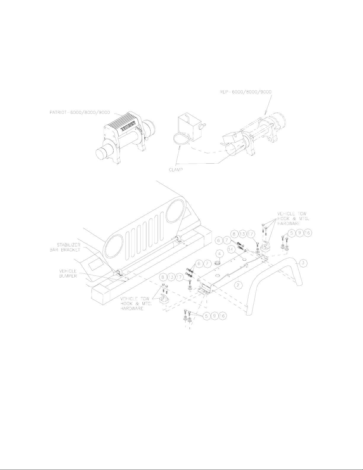
REP 6000/8000/9000 WINCH INSTALLATION SHOWN start at Step 1
(read carefully prior to beginning)
PATRIOT 6000/8000/9000 start at Step 2
1
Page 3

MATERIAL LIST (JEEP WRANGLER "TJ" KIT)
ITEM NO. QTY. PART NO. DESCRIPTION
1 1 424023 BAND CLAMP (INCLUDED WITH WINCH)
2 1 395233 MOUNTING PLATE
3* 1 395313 TUBE ASSEMBLY
4 1 472061 GROMMET
5 4 414551 CAPSCREW 1/2-13NC X 1-1/2 HXHD BLACK
6* 4 414146 CAPSCREW 5/16-18NC X 3/4 HXHD BLACK
7* 4 418172 LOCKWASHER 5/16 BLACK
8 2 415206 CAPSCREW M10 X 1.50 X 35MM LG. BLACK
9 4 418216 LOCKWASHER 1/2 BLACK
10 NOT USED
11 NOT USED
12 NOT USED
13 2 418196 LOCKWASHER 1-7/16 MED SECT. BLACK
14 1 472013 PLUG
15 3 440138 CABLE TIE
16 2 341002 LOOM
17 2 418174 FLATWASHER 3/8 BLACK
18 4 418229 FLATWASHER 1/2 BLACK
19 2 418518 SPACER
*INCLUDED IN SPORT BAR KIT #293015
TORQUE CHART
TORQUE
SIZE FT.LB. NM
1/4-20 5 7
5/16-18 12 16
M-10 34 46
1/2-13 74 100
2
Page 4

Step 1 - Mount Solenoid to Winch
REP 6000/REP8000/REP9000
1. Attach band clamp to solenoid base as shown below.
2. Slide clamp over end of motor and position at 45° angle for clearance.
3. Tighten clamp until snug.
Step 2 - Vehicle Preparation
1. Remove tow hooks, if so equipped on vehicle – to re-install tow hooks, refer to Customizing your
Vehicle, Step 8.
2. Remove Front Stabilizer Mounting Bracket Bolts - Discard.
3. Remove four (4) Upper Bumper Mounting Bolts - Discard.
Step 3 - Mounting Plate Preparation
1. Attach Rubber Grommet (#4) as shown in Assembly Graphic (page 1) to Mounting Plate (#2).
2. Attach Roller Fairlead (furnished with Winch) to Mounting Plate using hardware furnished with
winch.
3. At this time mount Grille Guard (kit #251062), if purchased separately, to mounting plate as shown
in assembly graphic. Use (2) 5/16-18NCx3/4 Hex Head capscrews with lockwasher, each side
(#6,#7). Tighten hardware to proper torque (see chart page 2).
3
Page 5

Step 4 - Mounting Winch to Mounting Plate
1. Refer to diagram above for reference.
2. 3" high spacers are required to support winch assembly.
3. Place Mounting Plate with winch on spacers to allow access to mounting holes for assembly.
4. Place four (4) flat washers and nuts into pockets on Winch legs.
5. Loosely attach winch to mounting plate with four (4) 3/8-16NCx1-1/4 capscrews with lockwashers
(furnished with winch) using front winch legs and 1 rear leg.
6. Route ground wire under grille avoiding brake lines and sharp edges (tie wrap in place)
7. Tighten all connections to proper torque (see chart on page 2).
8. If mounting a REP 6000/8000/9000 winch go to step 5.
If mounting a Patriot winch carefully remove spacers and set winch assembly on bumper.
4
Page 6

Step 5 - Electrical Connections
Refer to the winch owner’s manual for your specific winch for instructions on electrical connections.
HINT-Lubricate inside of boots with Silicone Spray to ease installation.
Step 6 - Mounting Winch Plate
1. Check to verify all wires are not pinched and are free from all sharp edges and engine components.
2. Align the six (6) attachment holes for mounting plate.
3. Front two (2) holes each side - Loosely install 1/2 capscrews, lockwashers and flat washers (#5, #9,
#18).
4. Loosely install M10 capscrew, lockwasher & flat washer (#8, #13, #17) each side.
5. Tighten all hardware per Torque Reference Chart page 2.
Step 7 - Battery Power Feed
1. Route both red (+) and black (-) wires from winch to vehicle battery - Five (5) cable ties (#15) are
supplied to kit, at this time select safe locations to insure good cable routing to battery.
2. Secure Battery Feed Wires at this time to vehicle.
3. Connect RED WIRE from Winch to (+) Battery Terminal using Spacer (item #19) and existing nut.
Connect BLACK WIRE from Winch to (-) Battery Terminal using Spacer (item #19) and existing nut,
as shown below.
4. Check Winch Operation per Winch Owner's Manual.
5. If inoperable, re-check ALL electrical connections.
5
Page 7

Step 8 - Customizing your Vehicle
Re-Installation of Tow Hooks
1. The driver side tow hook should be installed on the passenger side.
2. The passenger side tow hook must be installed on the driver side. Use vehicle tow hook mounting
hardware (see page 1).
If vehicle is equipped with factory bumper mount fog lights:
3. Problem now exists with clearance between hook and fog lights
- Light must be moved outboard at the discretion of the installer
- Bumper is hardened steel - sharp drills required
6
 Loading...