

Page 1
INSTALLATION INSTRUCTIONS FOR
ON - OFF SWITCH KIT # 282053
RAMSEY WINCH COMPANY
P.O. BOX 581510
TULSA, OKLAHOMA 74158
KI-912208-1199-B
Page 2
Step 1
1) Open hood of vehicle. Find adequate location, near battery, to mount switch #1. (Figure 1).
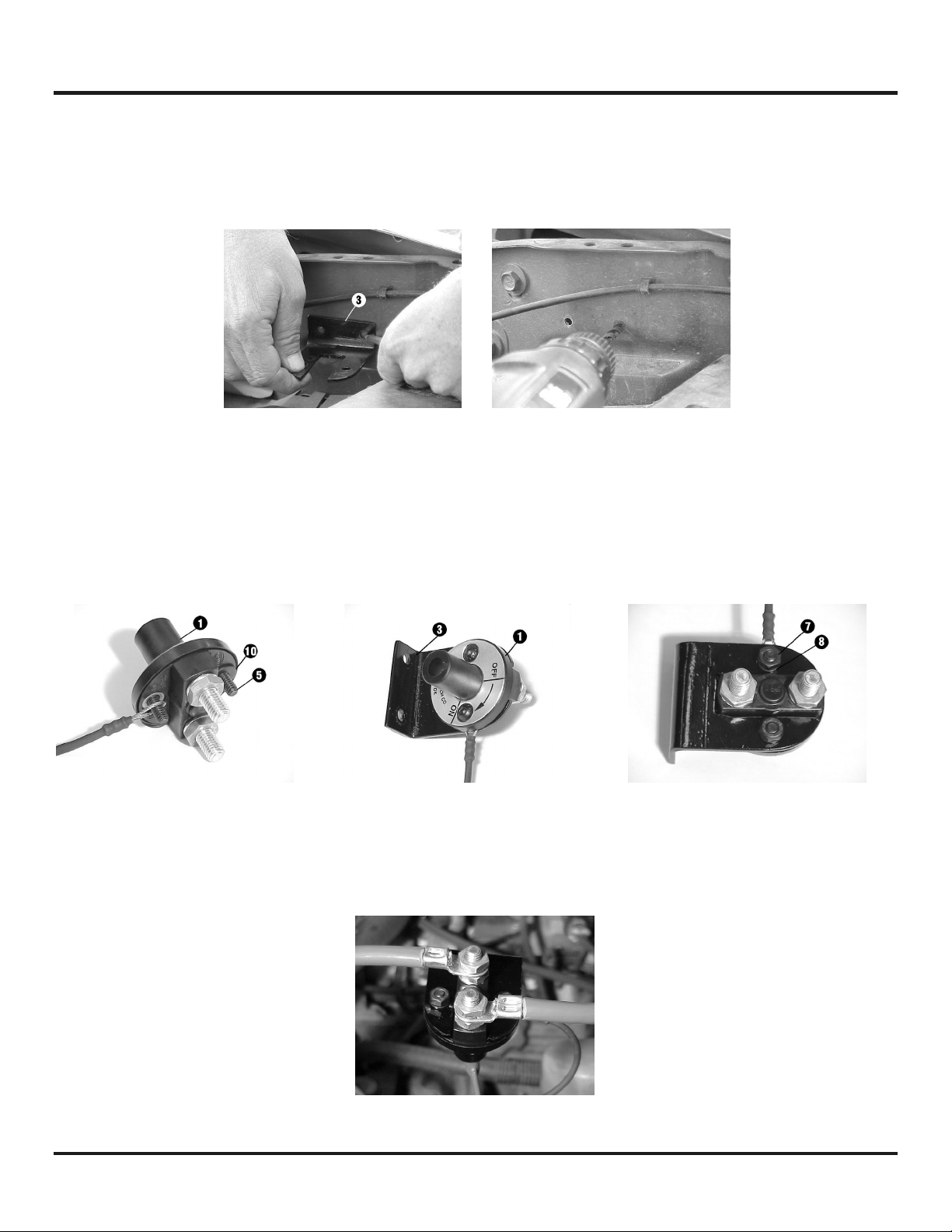
1) Use mounting bracket #3 as a guide to mark location of holes needed to mount switch.
2) Drill (2) 5/16” holes where marked.
Step 2
1) Install (2) 1/4-20NC X 3/4” black socket button head capscrews #5 through the switch. Place
2) Install switch #1 on bracket #3 and secure each side using black lockwasher #8 and nut #7.
flatwasher #10 on capscrew closest to the “OFF” position, and slip loop of lanyard over capscrew
closest to the “ON” position as shown (Figure 2).
Tighten to 80 in-lbs.
Figure 1
Figure 2
Step 3
1) Attach wire assembly #2 to one of the switch terminals. Secure using lockwasher and nut as
shown (Figure 3). Attach red power lead from winch to remaining switch terminal. Secure using
lockwasher and nut. Tighten securely.
Figure 3
1
KI-912208-1199-B
Page 3

Step 4
1) Mount bracket to vehicle using (2) 1/4-20NC X 3/4” plated hex head capscrews #4 (Figure 4).
2) Secure using flatwasher #10, lockwasher #9 and nut #6 for each capscrew. Tighten to 9 ft. lbs.
(13 Nm).
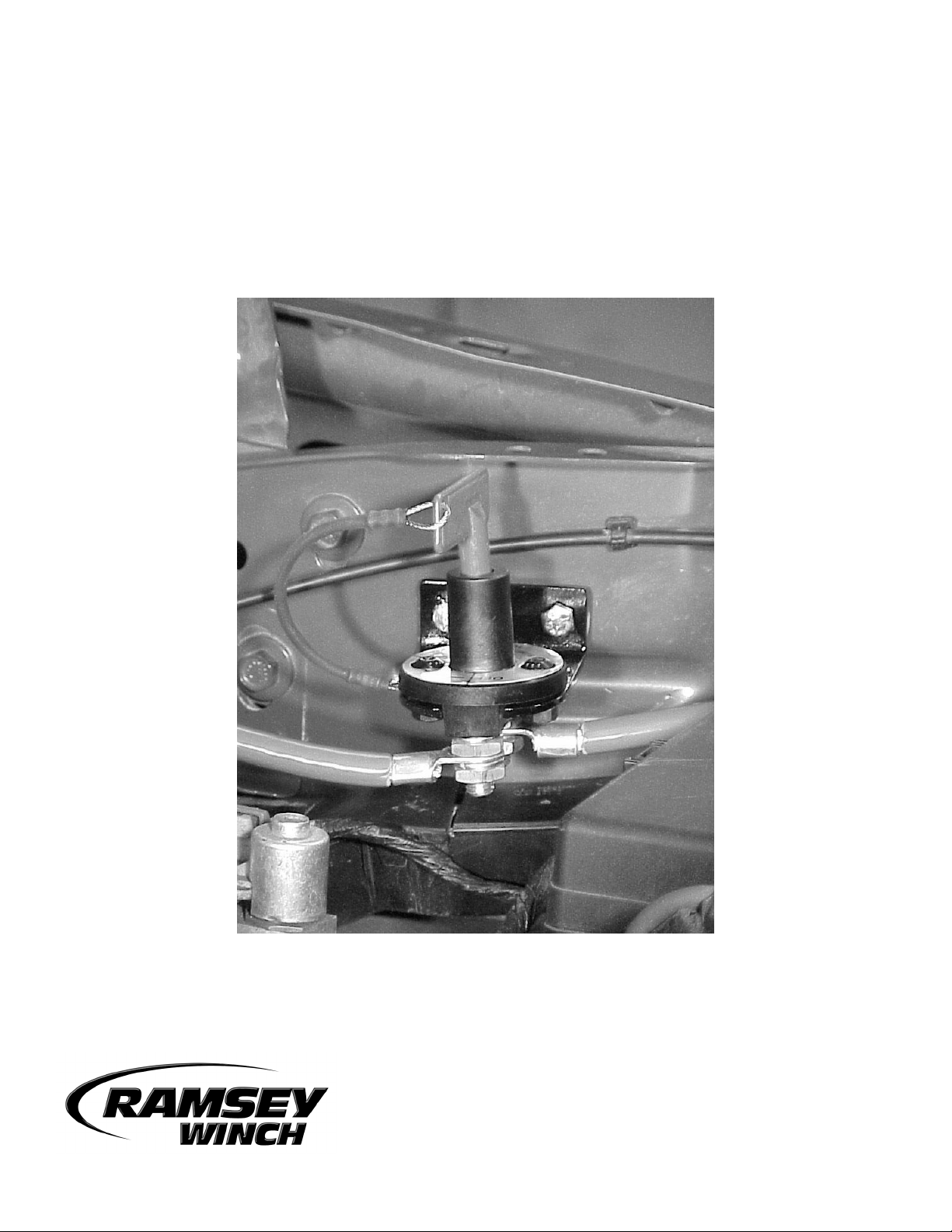
3) With switch in the “OFF” position, connect loose end of wire assembly #2 to positive (+) terminal of
battery. Be sure to maintain adequate clearance between the cable terminals as shown (Figure 4).
4) Test switch in “ON” and “OFF” position to insure proper operation.
PARTS LIST
ON-OFF SWITCH KIT #282053
Figure 4
Item # Part # Qty. Description
1 236024 1 On-Off Switch – Lanyard assembly
2 289094 1 Wire assembly
3 312554 1 Switch Mounting Bracket
4 414049 2 1/4-20NC X 3/4” Hx Hd Z/P Capscrew
5 414823 2 1/4-20NC X 3/4” Hx Soc But Hd F/B Capscrew
6 418014 2 Nut 1/4-20NC Hex, Z/P
7 418020 2 Nut 1/4-20 NC Hex, F/B
8 418147 2 Lockwasher 1/4 Med Sect. F/B
9 418149 2 Lockwasher 1/4 Med Sect. Z/P
10 418153 3 Washer 1/4 SAE Flat Z/P
11 450018 1 Spare Key
2
KI-912208-1199-B
 Loading...