

Page 1
INSTALLATION INSTRUCTIONS
FOR REPLACEMENT
MINI ROCKER SWITCH KIT
#256128
FOR ATV WINCH WITH
REMOTE MOUNTED
MANUAL SWITCH
Page 2
2
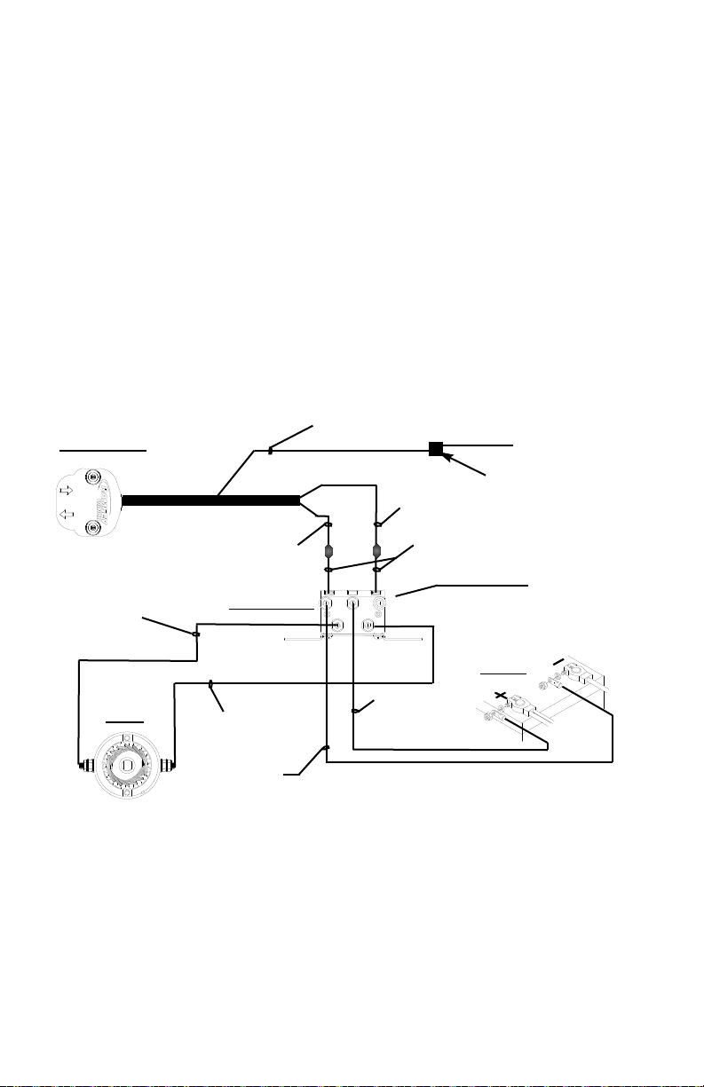
SOLENOID ASS’Y
.
BLACK W/ YELLOW
STRIPE MOTOR
LEAD
RED
BATTERY LEAD
BLACK
BATTERY LEAD
BATTERY
BLACK WIRE
BLACK MOTOR
LEAD
GREEN WIRE
RED WIRE
ROCKER SWITCH
#1
MOTOR
#2
NOTE:
TORQUE SOLENOID
TERMINAL NUTS TO
35-40 IN-LBS.
E
A
C
B
TO ATV IGNITION
SPLICE
Electrical Schematic
Before Beginning Installation
1. Locate Remote Mounted Switch and
Solenoid and disconnect all wiring to
battery and winch. Switch and Solenoid can
be removed and discarded.
2. Disconnect negative (-) battery cable
from battery. Turn off vehicle ignition.
3. Disengage winch clutch.
4. Remove hood or cowling as necessary for
easier access to installation area.
5. Locate and mark mounting location for
Solenoid Assembly.
6. Locate accessory wire from vehicle ignition
switch that is powered only when ignition is
ON. Use this wire when splicing to Red wire
on Rocker switch.
7. Make sure locations are close enough for
wiring connections to be made without making alterations to wire lengths.
CAUTION: DO NOT CONNECT NEGATIVE BATTERY
CABLE OR ENGAGE CLUTCH UNTIL INSTALLATION
IS COMPLETE
. WINCH COULD BEGIN SPOOLING
CABLE UNEXPECTEDLY CAUSING INJURY OR
DAMAGE TO WINCH
.
IN
OUT
WIRE CONNECTORS
Page 3
Solenoid Mounting: Choose a mounting
location that will remain protected and dry
(The best location will usually be where the
Solenoid for the Remote Switch was located.) Solenoid must be mounted within 24” of
winch motor. Solenoid should be mounted
on a flat surface.
Installing the Solenoid
1. Use Solenoid Assembly as a guide to
mark and drill (2) 7/32” holes in location
determined for solenoid OR if there is no
good place to drill holes for mounting,
use the tube clamps (item #1-16).
2. Use (2) 3/4” long #10 screws (item #1-
5), (2) #10 flat washers (item #1-8),
and (2) #10 zinc locknuts (item #1-10)
to mount solenoid. Tighten to 60 in-lbs
(7 Nm) torque.
Installing the Rocker Switch
For clarification, see wiring schematic on
page 2.
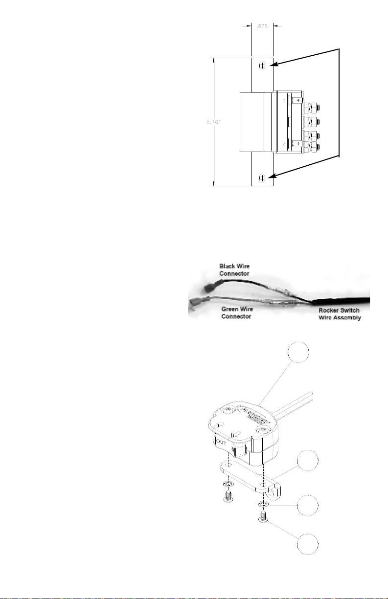
1. Install green Wire Connector (item #1-
14) to green wire on Rocker Switch (item
#2) and black Wire Connector (item #1-
15) to black wire on Rocker Switch, as
shown at right.
2. The Rocker Switch assembly (item #2)
will be assembled with the two halves of
the housing already attached. Install the
Mounting Bracket (item #1-2) using (2)
#6 screws (item #1-4) and shake-proof
washers (item #1-7). See figure at right.
Tighten securely. Do not overtighten.
3
Mounting Hole Pattern:
Two 7/32” holes spaced
4.5” apart
1-2
2
1-7
1-4
Page 4

4
3. Install (2) Handle Bar Clamps (item #1-
3) around ATV handle bars at a convenient location. Use a 3/4” long #10 screw
(item #1-5) and #10 locknut (item #1-
11) to secure them. See figures below.
Secure loosely, do not tighten.
4. Install the Mounting Arm (item #1-1) to
the Handle Bar Clamps using a 7/8” long
#10 screw (item #1-6), shake-proof
washer (item #1-9), and locknut (item
#1-11). Install the shake-proof washer
between the handle bar clamps and the
mounting arm. See figures below. Do not
tighten.
5. Install the Mounting Bracket (with rocker
switch attached) to the Mounting
Arm Bracket using a 3/4” long
#10 screw, shake-proof washer,
and locknut. Install the shake-proof
washer between the mounting arm
bracket and the mounting bracket.
6. Tighten all screws for the handle
bar clamps and mounting brackets
securely, positioning the rocker
switch as desired.
7. Route the Rocker Switch wire down the
handle bars to where the solenoid is
installed. Turn the handle bars fully right
and left to ensure enough slack in the
wire. Make sure wire is not drawn taut
across any surface that could damage it.
Use cable ties to anchor wire. Do not
connect wires to solenoid yet.
8. Push ATV Accessory wire and red wire
from switch into plastic splice (item #1-
12). Fold splice clip over itself and snap
closed.
NOTE:
LONGER SCREW
1-5
1-6
1-9
1-11
1-1
1-5
1-3
1-11
Page 5

5
Connect Wiring to Solenoid
C
AUTION: TIGHTEN NUTS ON TERMINAL STUDS
TO
35-40 IN-LBS. (3-4 NM) TORQUE. DO
NOT OVER
-
TIGHTEN.
For clarification, see wiring schematic on
page 2.
1. Connect Red Battery Lead (Item #3-3)
between “A” terminal on Solenoid and
positive (+) vehicle battery terminal.
2. Connect Black Motor Lead (item #3-1)
between #2 terminal on motor and C
terminal on solenoid. Connect Black
w/Yellow Stripe Motor Lead (item #3-2)
between #1 terminal on motor and B
terminal on solenoid.
3. Connect Black Battery Lead (item #3-4)
to “E” terminal on Solenoid and route to
negative (-) vehicle battery terminal but
do not connect.
4. Plug black wire from switch into right terminal (terminal above black with yellow
stripe motor lead). Plug Green wire from
switch into left terminal (terminal above
black motor lead).
Finish Installation
1. Confirm that winch clutch is disengaged.
2. Connect negative (-) battery cable to
vehicle battery. Connect Black Battery
Lead from winch to negative (-) vehicle
battery terminal.
3. With ignition switch OFF, press Rocker
switch to “OUT”—winch should not
operate. If the winch does operate with
the ignition off, confirm that proper
accessory wire from ignition was spliced.
4. Spool a few feet of cable out by hand.
Engage winch clutch. Turn ignition switch
ON and press Rocker switch to “OUT”—
winch should spool cable out. If winch
does not operate with ignition on, check
wiring against the schematic on page 1.
5. If winch spools cable IN instead of OUT,
turn off ignition and reverse black and
green wires on solenoid.
Page 6

6
PARTS LIST
ITEM
NO
. QTY. PART NO.DESCRIPTION
1 1 257560 HARDWARE KIT (see below)
2 1 282065 ROCKER SWITCH
3 1 299724 SOLENOID WIRING KIT (see below)
4 1 251234 SOLENOID ASSY
5 1 257522 HARDWARE KIT (Not pictured)
Hardware Kit, as shown on the opposite page, consists of the following components (Extra
parts included with kit but not used in this assembly may be discarded):
ITEM NO
. QTY. DESCRIPTION
1-1 1 Mounting Arm Bracket
1-2 1 Mounting Bracket
1-3 2 Handle Bar Clamp Bracket
1-4 2 Screw #6-32NC x 1/4” Socket Head Black
1-5 4 Screw #10-24NC x 3/4” Truss Cross Recess Black
1-6 1 Screw #10-24NC x 7/8” Truss Cross Recess Black
1-7 2 Washer #6 Shake Proof
1-8 1 Washer #10 Flat Zinc
1-9 2 Washer #10 Shake Proof
1-10 2 Locknut #10-24NC Hex Zinc
1-11 3 Locknut #10-24NC Hex Black
1-12 1 Wire Splice
1-13 1 Cable Ties (pkg. of 12) [not pictured]
1-14 1 Wire Connector (to green)
1-15 1 Wire Connector (to black)
1-16 2 Tube Clamps
Solenoid Wiring Kit, as shown on the opposite page, consists of the following components:
ITEM NO
. QTY. DESCRIPTION
3-1 1 37” Motor lead - black
3-2 1 37” Motor lead - black w/yellow stripe
3-3 1 97” Battery lead - red
3-4 1 97” Battery lead - black
Page 7

7
3-Solenoid
Wiring Kit
3
1
2
4
3
9
8
1
5
4
11
6
10
2
7
1-Hardware Kit
2-Rocker Switch
4-Solenoid
14
12
15
Page 8

RAMSEY WINCH COMPANY
P.O. BOX 581510
TULSA, OK 74158-1510 USA
PHONE: (918) 438-2760
FAX: (918) 438-6888
visit us at http://www.ramsey.com
913403-0108-B
Limited Lifetime Warranty
Ramsey Winch offers a limited lifetime warranty for each new
Ramsey ATV winch against manufacturing defects in workmanship and materials on all manufactured components.
Warranty registration cards for each winch must be submitted
at the time of purchase, or within 90 days. Online registration
of your winch is available at www.ramsey.com.
All Ramsey mounting kits and other accessories carry a 1- year
limited warranty against defects in materials and workmanship.
This warranty is void if winch is used in commercial/industrial
applications other than front mount self recovery.
Electrical components consisting of motors, solenoids, wiring,
wire connectors, and associated parts carr y a limited 1-year
warranty.
The obligation under this warranty, statutory or otherwise, is
limited to the replacement or repair at the manufacturers factory, or at a point designated by the manufacturer, of such par t as
shall appear to the manufacturer, upon inspection of such part,
to have been defective in material or workmanship. This
Warranty does not obligate Ramsey Winch Company to bear
the cost of transportation charges in connection with the
replacement or repair of defective parts, nor shall it apply to a
product upon which repairs or alterations have been made,
unless authorized by the manufacturer, or for equipment misused, neglected, or improperly installed.
Important notice: To the fullest extent permitted by applicable law, the following are hereby excluded and disclaimed:
1. All warranties of fitness for a particular purpose;
2. All warranties of merchantability;
3. All claims for consequential or incidental damages.
There are no warranties that extend beyond the descrip-
tion that appears on the face hereof.
Some states do not allow the above exclusions or dis-
claimers in consumer transactions and as such this disclaimer/exclusion may not apply to your particular case.
To the extent such warranties of fitness for a particular
purpose or merchantability are deemed to apply to this
product, they exist only for so long as the express limited
warranty elsewhere set forth is in existence.
Ramsey Winch Company makes no warranty in respect to
accessories, same being subject to the warranties of their
respective manufacturers.
Ramsey Winch Company, whose policy is one of continuous
product improvement, reserves the right to improve any product through changes in design or materials as it may deem
desirable without being obligated to incorporate such changes
in products of previous manufacture.
If field service at the request of the buyer is rendered and the
fault is found not to be with Ramsey Winch Company’s product, the buyer shall pay the time and expense of the field representative. Bills for service, labor or other expenses which have
been incurred by the buyer without express approval or authorization by Ramsey Winch Company will not be accepted.
This Warranty gives you specific legal rights and you may also
have other legal rights which vary from state to state.
 Loading...