

Page 1
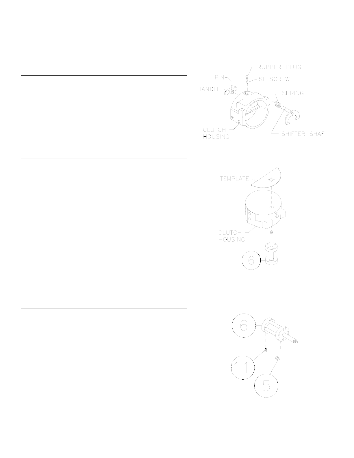
STEP 1
Remove winch assembly from mounting angle or
frame. Remove clutch housing assembly from winch.
Remove rubber plug and setscrew from clutch housing, discard rubber plug and setscrew. Drive pin from
handle and remove handle, spring and shifter shaft
from clutch housing. Discard spring, shifter shaft,
handle and pin.
STEP 2
Add holes to existing clutch housing:
Use the air cylinder as a guide for hole layout locations. This is accomplished by aligning the air cylinder (item #6) to the thru hole inside the clutch housing. Lower clutch housing (open end first) over the
air cylinder shaft. The end of the air cylinder shaft
should protrude through the closed end of the clutch
housing. Take template from page 5 and cut-out 1/2”
dia. hole. Lay template over clutch housing and air
cylinder shaft. Align the edges with the mounting
pads and clutch housing. Use a center punch at the
center locations of the four 5/32” (.156) diameter
holes to mark housing. Remove template and air
cylinder. Use 5/32” (.156) diameter drill to drill thru
housing at (4) center punched locations.
STEP 3
Air cylinder Sub-up:
Apply thread sealant to threads of elbow fitting (item
#5) and threads of breather vent (item #11). Attach
elbow fitting (item #5) to port at shaft end of air cylinder (item #6), pay attention to position the end of the
elbow fitting 180 degrees from the shaft, as shown.
Attach the breather vent (item #11) to the port at the
other end of the air cylinder.
1
912585-0905-B
Installation Instructions for Air Shifter Kit #256103
Page 2
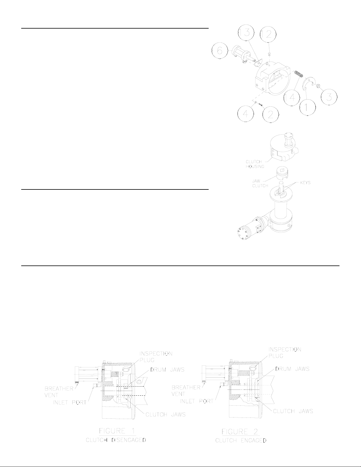
STEP 4
Air cylinder to clutch housing sub-up:
Insert shaft of air cylinder through hole in shim (item #13),
then insert shaft of air cylinder (item #6) into hole of clutch
housing, as shown. Line up holes of air cylinder and shim
to holes drilled previously in clutch housing. Pay attention
to allow flat portion of shim to be at the top to provide
clearance between the letters on the clutch housing and
the air cylinder. Install the bottom 2 socket hd. capscrews
(item #2) with lockwashers (item #4) from inside of the
clutch housing and torque to 28 in.lbs. each, so that the
shim will remain tight against the air cylinder and not allow
it to pivot. Install the top 2 remaining capscrews and lockwashers and torque to 28 in.lbs. each. Place spring (item
#14) over shaft and place yoke (item #1) over threads at
end of air cylinder shaft. While holding the air cylinder
shaft at the wrench flats tighten down the flex locking nut
(item #3), torque to 170 in.lbs.
STEP 5
Clutch housing assembly to winch:
Apply grease to keys and end of shaft. Place clutch housing over end of drum shaft. Pull jaw clutch upward, toward
clutch housing, enough to allow yoke, in clutch housing, to
fit properly in groove around jaw clutch. Air may have to
be applied to force housing down onto drum. Reinstall
winch into mounting frame.
STEP 6
Verify clutch ENGAGED and DISENGAGED positions:
Hook up air to inlet port of air cylinder.
Apply air pressure (60-125 psi) to disengage clutch. Rotate drum by hand to verify free spool.
Remove inspection plug, rotate drum until clutch jaws line up with drum jaws. Remove air pressure
so clutch jaws rest against drum jaws (See FIGURE 1). Rotate drum and observe if clutch jaws
engage fully with drum jaws (See FIGURE 2). Repeat three times.
Replace inspection plug.
2
Page 3

STEP 7
Winch clutch operation and data tag modifications:
Clutch operations decal (item #9) must be affixed over clutch operation portion of data tag on winch.
Warning decal (item #10) must be affixed over warning portion of tag on winch.
The clutch is spring loaded for engagement when air pressure is removed from air shifter. Verify air
shifter control valve lever position for engaged position. The clutch engagement tag (item #7) must
be mounted as near as possible to air shifter control lever in the ENGAGED position.
The clutch is dis-engaged by applying 60-125 psi air pressure to air shifter. Verify air shifter control
valve lever position for dis-engaged position. The clutch dis-engaged tag (item #8) must be mounted
as near as possible to air shifter control lever in the DIS-ENGAGED position.
Ram-Lok®Air-Shifter Clutch Operations
The Ram-Lok
®
air-shifter clutch allows rapid unspooling of the cable, from cable drum, for hooking
onto the load. The clutch is operated by an air cylinder as follows:
TO DISENGAGE CLUTCH, run the winch in the reverse (reel out) direction until the load is off
the cable. Apply 60-125 PSI to inlet port fitting of air cylinder.
TO ENGAGE CLUTCH, remove air pressure from air cylinder. Run the winch in reverse until
the cable drum starts turning. The plastic plug in top of clutch housing may be removed, for
inspection of clutch to assure total engagement. After the clutch is fully engaged, the winch is
ready for winching in the cable.
3
Page 4

PARTS LIST FOR KIT #256103
ITEM NO.
QTY. PART NO. DESCRIPTION
1 1 370043 YOKE-SHIFTER
2 4 416198 SCREW #6-32 NC X 1 LG. HX.SOC.HD.
3 1 418044 NUT 3/8-16NC FLEX-LOK
4 4 418136 LOCKWASHER #6 MED.SECT.
5 1 432033 FITTING-ELBOW
6 1 433021 AIR CYLINDER
7 1 434385 TAG-CLUTCH ENGAGED
8 1 434386 TAG-CLUTCH DISENGAGED
9 1 434388 DECAL-CLUTCH AIR SHIFTER
10 1 434389 DECAL-AIR SHIFTER WARNING
11 1 456038 FITTING-VENT BREATHER
12 1 472012 PLUG-RUBBER
13 1 488012 SHIM-AIR SHIFTER
14 1 494053 SPRING
4
Page 5

 Loading...