

Page 1
OPERATING, SERVICE AND
MAINTENANCE MANUAL
20,000 LB INDUSTRIAL
CAUTION: READ AND UNDERSTAND THIS MANUAL BEFORE INSTALLATION AND OPERATION OF
WINCH. SEE WARNINGS!
WINCH
Page 2

TABLE OF CONTENTS
WARRANTY INFORMATION ........................................................................................................................... 1
SPECIFICATIONS.......................................................................................................................................... 1
WARNINGS................................................................................................................................................... 1
CABLE INSTALLATION .................................................................................................................................. 2
HYDRAULIC SYSTEM REQUIREMENTS........................................................................................................... 3
PERFORMANCE CHARTS .............................................................................................................................. 3
CLUTCH OPERATION .................................................................................................................................... 4
WINCH OPERATION...................................................................................................................................... 4
MAINTENANCE............................................................................................................................................. 4
TROUBLE SHOOTING GUIDE.......................................................................................................................... 5
INSTRUCTIONS FOR OVERHAUL.................................................................................................................... 6
TORQUE CHART ......................................................................................................................................... 13
20K DIMENSIONAL DRAWING .................................................................................................................... 15
20K WINCH PARTS DRAWING..................................................................................................................... 16
PARTS LIST – 20K WINCH .......................................................................................................................... 17
LIMITED WARRANTY .................................................................................................................................. 18
Page 3

RAMSEY HYDRAULIC PLANETARY WINCH MODEL 20K
PLEASE READ THIS MANUAL CAREFULLY
This manual contains useful ideas in obtaining the most efficient operation from your Ramsey Winch, and safety
procedures one needs to know before operating a Ramsey Winch. Do not operate this winch until you have carefully
read and understand the "WARNINGS" and "OPERATION" sections of this manual.
WARRANTY INFORMATION
Ramsey Winches are designed and built to exacting specifications. Great care and skill go into every winch we make.
If the need should arise, warranty procedure is outlined on the back of your self-addressed postage paid warranty card.
Please read and fill out the enclosed warranty card and send it to Ramsey Winch Company. If you have any problems
with your winch, please follow instructions for prompt service on all warranty claims. Refer to back page for limited
warranty.
SPECIFICATIONS*
NOTE: The rated line pulls shown are for the winch only. Consult the wire rope manufacturer for wire rope ratings
.
Rated Line Pull (lbs.) …………………………………………………………………………. 20,000
(Kg.) ………………………………..……………………………………….. 9070
Gear Reduction …………………………………………..……………………………………… 21:1
Weight (without cable) 20K Winch………………………………….…………….…………. 337 lbs
LAYER OF CABLE 1 2 3 4 5
*Rated line pull
per layer
* Cable Capacity per Layer
20K Winch
* Line Speed
(at 30 GPM)
* These specifications are based on recommended wire rope of 9/16" Extra Improved Plow
Steel cable and a 14.9 cu. in. / Rev. motor.
lbs. 20,000 17,300 15,200 13,600 12,300
Kg. 9,070 7,840 6,890 6,160 5,570
ft. 30 70 115 165 220
m 9 21 35 20 67
FPM 42 47 53 59 65
MPM 12.1 13.6 15.5 17 18.8
WARNINGS:
CLUTCH MUST BE FULLY ENGAGED BEFORE STARTING THE WINCHING OPERATION.
DO NOT START WINCH MOTOR BEFORE ENGAGING CLUTCH.
DO NOT DISENGAGE CLUTCH UNDER LOAD.
STAY OUT FROM UNDER AND AWAY FROM RAISED LOADS.
STAND CLEAR OF CABLE WHILE PULLING. DO NOT TRY TO GUIDE CABLE.
DO NOT EXCEED MAXIMUM LINE PULL RATINGS SHOWN IN TABLE.
DO NOT USE WINCH TO LIFT, SUPPORT, OR OTHERWISE TRANSPORT PEOPLE.
A MINIMUM OF 5 WRAPS OF CABLE AROUND THE DRUM BARREL IS NECESSARY TO HOLD THE LOAD.
CABLE ANCHOR IS NOT DESIGNED TO HOLD LOAD.
1 OM-914209-0508-A
Page 4
CABLE INSTALLATION
1. Unwind cable by rolling it out along the ground to prevent kinking. Securely wrap end of wire
rope, opposite hook, with plastic or similar tape to prevent fraying.
2. Place taped end of cable through roller guide and into hole in cable drum as shown below. Use
3/8”-16NC X 3/8” Lg. Hex socket drive setscrew to secure cable to drum.
3. Carefully run the winch in the “reel-in” direction. Keeping tension on end of cable, spool all the
cable onto the cable drum, taking care to form neatly wrapped layers.
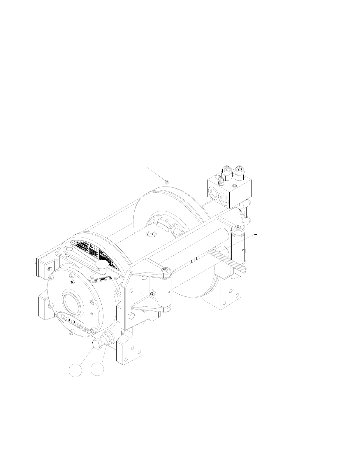
After installing cable, check freespool operation. Disengage clutch and pull on cable at walking
speed. If cable “birdnests”, loosen jam nut #34 and turn 3/8”-16NC capscrew #29 clockwise to
increase drag on drum. If cable pull is excessive, loosen 3/8”-16NC capscrew #29 by turning
counterclockwise. Tighten jam nut when proper setting is obtained.
SETSCREW
INSERT CABLE
BETWEEN HORIZONTAL
ROLLERS OF ROLLER
GUIDE AND INTO POCKET
ON DRUM AS SHOWN
SECURE WITH SETSCREW
29
34
2 OM-914209-0508-A
Page 5
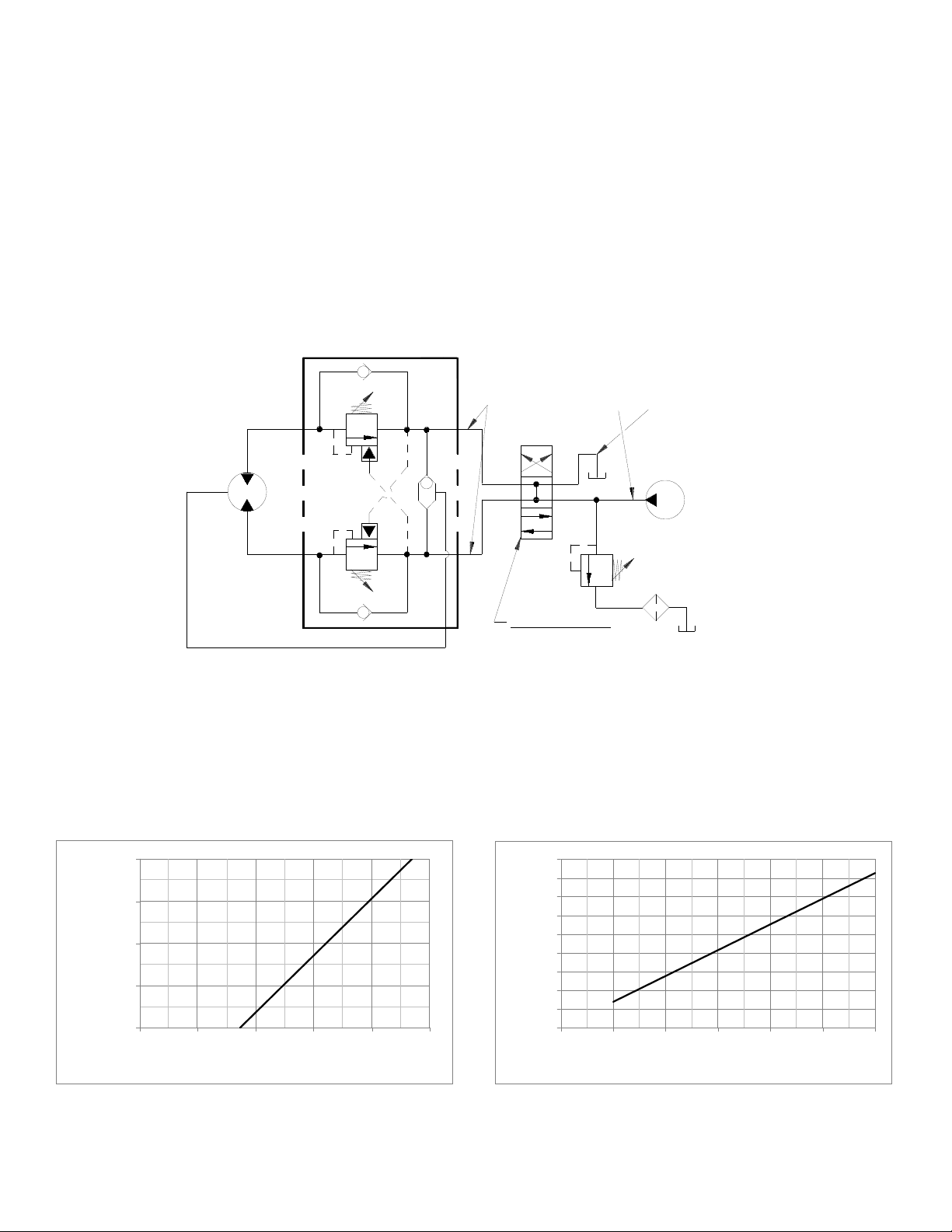
HYDRAULIC SYSTEM REQUIREMENTS
Refer to the performance charts, below, to properly match your hydraulic system to Linemaster 20K winch
performance. The charts consist of:
(1) Line pull (lb.) first layer vs. working pressure (PSI) and (2) Line speed, first layer (FPM) vs. gallons per
minute (GPM). Performance based on a motor displacement of 14.9 cubic inches with 30 GPM maximum
flow rate. Motor has (2) 1.062-12 SAE straight thread o-ring ports.
Note: A motor spool (open center) directional control valve is required for brake operation.
TYPICAL LAYOUT
DUAL-A & B PORT CONTROL
WITH BRAKE RELEASE SHUTTLE
HIGH PRESSURE LINE
LOW PRESSURE LINE
MOTOR
BRAKE
PORT
A
B
PERFORMANCE CHARTS
20000
15000
10000
FIRSTLAYER
LINEPULL,LBS
5000
BASED ON 14.9 CU IN/REV MOTOR
0
0 500 1000 1500 2000 2500
WORKINGPRESSURE,PSI
CONTROL VALVE
(MOTOR SPOOL)
LINESPEED,FT/MIN
PUMP
3 POSITION
4 WAY VALVE
45
40
35
30
25
20
FIRSTLAYER
15
10
5
0
0 5 10 15 20 25 30
FLOW,GPM
3 OM-914209-0508-A
Page 6

CLUTCH OPERATION
WARNING: CLUTCH MUST BE FULLY ENGAGED BEFORE STARTING THE WINCHING OPERATION.
To engage clutch:
1. Grasp shift lever and push toward drum to the “In” position.
2. If shift lever detent does not engage to the detent hole, then the clutch is not fully engaged. The
cable drum may need to be manually rotated slightly while pushing on the shift lever to align the
clutch splines.
WARNING: DO NOT DISENGAGE CLUTCH UNDER LOAD.
To disengage clutch:
1. Run the winch in the "cable out" direction until the load is off the cable.
2. Grasp the shift lever and pull away from drum to the “Out” position until shift lever detent engages
in detent hole. If there is resistance in moving the shift lever, the cable drum may be manually
rotated in the cable “Out” direction thereby relieving the preload and allowing the lever to shift.
The cable may now be pulled off by hand.
WINCH OPERATION
The best way to get acquainted with how your winch operates is to make test runs before you use
it. Plan your test in advance. Remember, you hear your winch, as well as see it operate; learn to
recognize the sounds of a light steady pull, a heavy pull, and sounds caused by load jerking or
shifting. Gain confidence in operating your winch and its use will become second nature with you.
The uneven spooling of cable, while pulling a load, is not a problem, unless there is a cable pileup
on one end of drum. If this happens reverse the winch to relieve the load and move your anchor
point further to the center of the vehicle. After the job is done you can unspool and rewind for a
neat lay of the cable.
MAINTENANCE
Adhering to the following maintenance schedule will keep your winch in top condition and performing
as it should with a minimum of repair.
A. WEEKLY
1. Check the oil level and maintain it to the oil level plug. If oil is leaking out, determine location and
repair.
Check the pressure relief plug on the gear housing cover. Be sure that it is not plugged. Lubricate
2.
cable with light oil.
B. MONTHLY
1. Check the winch mounting bolts. If any are missing, replace them and securely tighten any that are
loose. Use grade 8 or better bolts.
2. Inspect the cable. If the cable has become frayed with broken strands, replace immediately.
4 OM-914209-0508-A
Page 7

C. ANNUALLY
1. Drain the oil from the winch annually or more often if winch is used frequently.
2. Fill the winch to the oil level plug with clean kerosene. Run the winch a few seconds with no load in the
reel in direction. Drain the kerosene from the winch.
3.
Refill the winch to the oil level plug with all purpose SAE 80W-140 gear oil.
4. Inspect bumper and surrounding structure for cracks or deformation.
TROUBLE SHOOTING GUIDE
--------------------------------------------------------------------------------------------------------------------------------------
CONDITIONS POSSIBLE CAUSE CORRECTION
--------------------------------------------------------------------------------------------------------------------------------------
OIL LEAKS FROM WINCH 1. Seals damaged or worn. 1. Replace seal.
2. Too much oil. 2. Drain excess oil. Refer
to OPERATION.
3. Damaged gaskets. 3. Replace gaskets.
4. Damaged o-rings. 4. Replace o-rings.
--------------------------------------------------------------------------------------------------------------------------------------
WINCH RUNS TOO SLOW 1. Low flow rate 1. Check flow rate. Refer to
HYDRAULIC SYSTEMS
performance chart page 3.
2. Hydraulic motor worn out. 2. Replace motor.
-------------------------------------------------------------------------------------------------------------------------------------
CABLE DRUM WILL NOT 1. Clutch not disengaged 1. Check operation, refer to page
FREESPOOL 4.
---------------------------------------------------------------------------------------------------------------------------------------
BRAKE WLL NOT HOLD 1. Incorrect directional control 1. Use only a motor spool (open
valve. (Cylinder spool, closed center) directional control
center). valve.
5 OM-914209-0508-A
Page 8

INSTRUCTIONS FOR OVERHAUL
1. Drain oil from gear housing by removing plug #74 from drain hole in end bearing.
74
2. Freespool drum to locate drain hole in bottom. Remove plugs #55 from barrel of drum. Drain oil
from drum barrel. Remove tie plate #21 by loosening (2) capscrews #28 each side. Loosen but
do not remove (2) capscrews #27 on roller guide tie plate #22. Remove (4) capscrews #28 and
roller guide.
28
55
28
55
21
22
27
28
28
6 OM-914209-0508-A
Page 9

3. Position roller guide face down on a level surface and (2) capscrews #27 and roller guide tie
bar #22. Horizontal rollers #37 can be removed from the left and right hand roller guides once
the tie bar has been removed. Horizontal rollers #37 have (2) lube fittings #43, one located at
either end of the roller.
22
37
27
27
4. Remove vertical roller pin #61 from right hand side of roller guide #14 by removing spring pin
#63. Spring pins should be removed by driving inward through the roller. Vertical roller pin #61
has (2) lube fittings #43, one located at either end of the roller pin. Once the vertical roller pin
is removed from right hand side of roller guide, vertical roller #38 can be removed. Remove
vertical roller from left hand side of roller guide #15 in the same way.
14
38
38
63
43
61
43
15
61
63
43
7 OM-914209-0508-A
43
Page 10

5. Remove (6) capscrews #30 and clutch housing cover #7. Remove relief fitting #44 and plug
#54 from clutch housing cover #7 as shown. Remove clutch housing o-ring #52 and plug #64.
Pull shifter lever away from drum and slide clutch yoke #20 from shaft.
20
52
44
30
64
7
54
8 OM-914209-0508-A
Page 11

6. Slide clutch end bearing #2 from drum. Drum freespool drag puck #12, drum freespool spring
# 68, and brake disc spacer # 73 will fall out when end bearing is removed from drum. Retain
these items for re-assembly.
To remove shifter yoke #19, drive spring pin #59 inward through shifter yoke. Lift shifter
assembly out by pulling up on shifter handle assembly #5 until shifter shaft #18 is clear of
shifter yoke #19. Yoke can then be lifted out of end bearing.
To replace handle #5 on shifter shaft #18, first remove spring pin #59, then slide handle
assembly #5 from shifter shaft #18. O-ring #53 can be replaced at this time.
To replace shifter detent bracket #23, first remove (2) ¼ x 20 capscrews #26 and (2) ¼
lockwashers # 35, then remove shifter detent bracket #23 and replace.
5
53
58
19
59
18
2
73
12
68
74
54
34
29
26
35
23
9 OM-914209-0508-A
Page 12

7. Remove drum bushing assembly #25. Note that the (6) spring pins #62 are pressed into the
bushing and cannot be removed. To replace the drum bushing, first press in the (6) spring pins
#62, and then replace the bushing on the shaft. Drum seal #65 can also be replaced at this
time if needed.
Note: Replacement bushings do not include the pins so you will need to order them
separately.
25
65
62
10 OM-914209-0508-A
Page 13

8. Remove output shaft #16, output carrier assembly #1, and input carrier assembly #6 from
drum #13. Disassemble in the following order:
Knock (3) spring pins #57 inward to center of input carrier assembly #6. Remove (3) input
planet pins #60 from input carrier assembly #6. Remove (3) input planet gears #4 from input
carrier assembly #6.
Remove output shaft external retaining ring #67 from output shaft #16. Slide input carrier #6
from output shaft #16.
Remove thrust washer #72 from output shaft #16. Slide output carrier assembly #1 from output
shaft #16. Output carrier assembly #1 must be purchased as an assembly. Replacement gears
are not available.
16
1
72
6
57
4
60
57
4
60
13
4
57
67
60
11 OM-914209-0508-A
Page 14

9. Remove drum #13 from motor end bearing #3. Remove drum seal #65. Check for signs of
wear and replace if necessary.
13
10. Remove input shaft #17 from motor end bearing #3.
65
3
3
17
12 OM-914209-0508-A
Page 15

11. To remove motor #45 from motor end bearing #3, first detach hydraulic brake release hose
assembly #70 from elbow fitting #40. Loosen (2) ½-13 capscrews #32. Remove motor gasket
#42, and (11) brake springs #69.
To remove motor control valve #71, loosen (3) 3/8-16 NC capscrews #31, lift motor control
valve #71 from motor #45.
Note: Do not run winch with hydraulic brake release hose assembly disconnected.
70
40
3
69
70
41
TO ITEM 40
42
TO ITEM 41
31
71
45
TORQUE CHART
GRADE 5
SIZE TORQUE VALUE
1/4-20 76 IN LBS
3/4-16 223 FT LBS
3/8-16 23 FT LBS
1/2-13 57 FT LBS
GRADE 8
SIZE TORQUE VALUE
1/2-13 80 FT LBS
5/8-11 159 FT LBS
32
13 OM-914209-0508-A
Page 16

12. Remove (2) retaining rings #66. Remove motor coupling #39 from end bearing #3. Remove roll
pin #56 from motor coupling #39. Remove brake piston #10 and backup brake piston #11.
Remove o-ring #47, o-ring #46, backup ring #49, and backup ring #51from brake piston #10.
Remove o-ring #48 and backup ring #50 from backup brake piston #11. Remove (7) stators #8
and (6) brake discs #9 from end bearing #3.
To re-install brake, set gear housing end down on work surface.
Install well-oiled o-rings and backup rings into grooves on outside of brake piston and backup
brake piston as shown in cross-section A-A below.
Piston, backup piston, brake discs and stators must be clean and well lubed with 80W-140 oil.
Insert (7) stators #8 and (6) brake discs #9 into gear end alternating, with stators first and last.
Insert backup brake piston #11 on to brake piston #10. Insert brake piston assembly into motor
end bearing #3. Apply even pressure on piston when installing.
Insert roll pin #56 into motor coupling #39 below bottom of spline teeth. Insert motor coupling
#39 into end bearing #3.
Install (2) retaining rings #66 into grooves in motor end housing.
3
8
41
9
50
46
51
11
11
48
SECTION A-A
50
48
47
49
10
51
MOTOR SIDEDRUM SIDE
46
10
47
A
A
49
39
66
56
14 OM-914209-0508-A
Page 17

15
20K DIMENSIONAL DRAWING
18.13
10.69
ENGAGED POSITION
DISENGAGED POSITION
(SHOWN)
8.19
20K Dimensional Drawing
Ø13.25
FLANGE
OIL FILL PLUG
(16 OZ. 80W-140 GEAR OIL)
Ø6.75
BARREL
Ø1.50
(TYP)
10.28
3.94
(TOP OF BOTTOM ROLLER)
(ROLLER OPENING)
Ø.625
CABLE
ANCHOR
27.46
Ø1.00
12.75 (PORT LOCATION)
Ø1.50
(TYP)
OIL FILL PLUG
(16 OZ. 80W-140 GEAR OIL)
16.36
VENT
7.50
3.08
(PORT)
6.75
6.75
13.50
DRUM FREE SPOOL
ADJUSTMENT BOLT
5.38
1.13
2.12
OIL LEVEL PLUG
5.491.06
6.82
DRUM C
10.99
13.63
19.00
L
1.06
2.13
9.49
1.062-12 SAE STRAIGHT
THREAD O'RING PORT
(2-PLACES)
1/2-13 X 1.00 DEEP
TAPPED HOLES
(4-PLACES EACH SIDE OF WINCH)
6.63
Page 18

20K WINCH PARTS DRAWING
44
30
28
21
28
7
52
65
64
26
29
35
34
20
23
58
19
74
16
1
72
57
4
60
54
4
57
60
4
57
6
67
60
55
13
33
17
5
53
18
59
2
65
25
62
16
15
43
63
38
43
27
61
63
38
43
37
61
27
28
55
22
43
14
54
8
11
3
41
70
9
50
48
74
10
51
73
68
46
56
12
49
47
39
31
40
71
66
32
69
42
45
28
Page 19

Y
Y
PARTS LIST – 20K WINCH
17
ITEM QTY . PART NO DE SCRIPTION ITEM QTY. PART NO DESCRIPTION
1 1 247040 OUTPUT CARRIER 39 1 431023 COUPLING-MOTOR
2 1 296673 CLUTCH END BEARING 40 1 432018 F ITTING-90
3 1 296674 MOTOR END BEARING 41 1 432044 F ITTING-45° ELBOW, -4 SAE ORING TO -4 JIC
4 1 296675 INPUT PLANE T GEA R ASSEMBL
5 1 296682 SHIFT LEVER ASSEMBL
6 1 317015 CARRIER-INPUT 44 1 456008 RE LIEF FITTING ZP
7 1 328166 COVER-CLUTCH HOUSING 45 1 458144 H YD MOTOR 14.9 CU IN
8 7 330011 STATOR-BRAKE 46 1 462067 O-RING-2.225 I D X .2 10 THK , 2-331
9 6 330012 DISC-BRAKE FRICTION 47 1 462068 O-RING- 3.10 ID X .21 0 THK, 2-338
10 1 33 0013 PISTON-BRA KE 48 1 462069 O-RING- 2.975 ID X .2 10 THK , 2-337
11 1 33 0014 PISTON-BACKUP BRAKE 49 1 462070 RI NG-BACKUP, 3.143 ID X .0 76 THK, 8-338
12 1 33 0015 PUCK-DRAG, DRUM FREESPOOL 50 1 462071 RI NG-BACKUP, 3.018 ID X .0 76 THK, 8-337
13 1 33 2231 DRUM-MACHINED 51 1 462072 RI NG-BACKUP, 2.268 ID X .0 76 THK, 8-331
14 1 33 3026 ROLLER GUIDE-RH SIDE 52 1 462077 O-RING- 6.984 ID X .1 39 THK , 2-262, CLUTCH HSG CVR
15 1 33 3027 ROLLER GUIDE-LH 53 1 462078 O-RING- .549 ID X .10 3 THK, 2-113, SHIFTER SHAFT
16 1 33 4207 OUTPUT SUN GEAR 54 2 468016 PLUG-PIPE 1/8-27NPTF SOC HD
17 1 35 5139 SHAFT-INPUT 55 2 468041 PLUG, -8 SAE, 3/4"- 16 UNF
18 1 35 5141 SHAFT-SHIFTER 56 1 470033 S PIROL PI N
19 1 37 0061 YOKE-SHIFTER 57 3 470060 S PRING PIN-3/16 X 1/ 2 LG
20 1 37 0065 CLUTCH-YOKE 58 1 470103 PIN-SPRING, .25 DIA X 1.0 LG
21 1 39 5428 TIE PLATE 59 1 470104 PIN-SPRING, .25 DI A X 1.5 LG
22 1 39 5429 ROLLER GUIDE TIE PLATE 60 3 470107 PIN-INPUT PL ANET
23 1 40 8364 BRACKET-SHIFTER DETENT 61 2 470109 VERTICA L ROLLER PIN
25 1 41 2132 BUSHING-DRUM 62 6 47 0123 PIN-SPRING, .188 DIA X 1 .00 LG
26 2 41 4038 CAPSCREW-1 /4-20NC X .75 LG HX HD GR5 Z/P 63 2 470128 PIN-SPRING .188 DIA X 1. 5 LG
27
2 414512 CAPSCREW 1/2 -13X1.5 LG H X HD GR 8 ZP
28 8 41 4515 CAPSCREW 1/2 -13X1.75 LG HX HD GR 8 ZP 65 2 486093 S EAL-DRUM
29 1 41 4772 CAPSCREW-3 /4-16 X 2.0 LG HX HD GR5 66 2 490049 RI NG-INTERNAL RETAINING, SMALLEY #WH-350
30 6 41 4906 CAPSCREW-3/8-16 X 1.5 LG SOC H D F/B 67 1 490061 RI NG-EX TERNAL RETAINING, SMALLEY #WSM- 150, OUTPUT SH AFT
31 3 41 4935 CAPSCREW-3 /8-16NC X 2.5 L G SOC HD 68 1 494002 S PRING-DRUM FREESPOOL
32 2 41 4945 CAPSCREW 1/2 -13 X 1.5 LG SOC HD ZP, NY-LOK 69 11 494124 S PRING-BRAKE
33 1 41 6057 SETSCREW-3/8-16NCX3/8LG,HX SOCH D CU 70 1 509142 H OSE ASSY- P ORTS UP
34 1 41 8098 NUT-3/4-16NF HEX JAM 71 1 516011 VA LVE-MOTOR CONTROL
35 2 41 8149 LOCKWASHER-1/4 MED SE CTION ZP 72 1 518071 THRUST WASHER
37
2 424033 ROLLER-HORIZONTAL
38
2 424034 ROLLER-VERTICAL
42 1 442223 GA SKET-MOTOR
43 8 456001 LUBE FI TTING
64 1 472081 PLUG, GEAR H OUSING COVER
73 1 530094 S PACER-BRAKE DISC
74 2 468018 PLUG - 3/8-18 HX SOC
ELBOW, -4 SAE ORING TO -4 JIC
°
Page 20

LIMITED WARRANTY
RAMSEY WINCH warrants each new RAMSEY WINCH to be free from defects in
material and workmanship for a period of one (1) year from date of purchase.
The obligation under this warranty, statutory or otherwise, is limited to the
replacement or repair at the Manufacturer's factory, or at a point designated by the
Manufacturer, of such part that shall appear to the Manufacturer, upon inspection of
such part, to have been defective in material or workmanship.
This warranty does not obligate RAMSEY WINCH to bear the cost of labor or
transportation charges in connection with the replacement or repair of defective
parts, nor shall it apply to a product upon which repair or alterations have been
made, unless authorized by Manufacturer, or for equipment misused, neglected or
which has not been installed correctly.
RAMSEY WINCH shall in no event be liable for special or consequential damages.
RAMSEY WINCH makes no warranty in respect to accessories such as being
subject to the warranties of their respective manufacturers.
RAMSEY WINCH, whose policy is one of continuous improvement, reserves the
right to improve its products through changes in design or materials as it may deem
desirable without being obligated to incorporate such changes in products of prior
manufacture.
If field service at the request of the Buyer is rendered and the fault is found not to
be with RAMSEY WINCH's product, the Buyer shall pay the time and expense to
the field representative. Bills for service, labor or other expenses that have been
incurred by the Buyer without approval or authorization by RAMSEY WINCH will not
be accepted.
See warranty card for details.
RAMSEY WINCH COMPANY
Post Office Box 581510
Tulsa, Oklahoma 74158-1510
Telephone: (918) 438-2760 FAX: (918) 438-6688 OM-914209-0508-A
 Loading...