

Page 1
16K HYDRAULIC PLANETARY
CAPSTAN DRIVE
CAUTION: READ AND UNDERSTAND THIS MANUAL BEFORE INSTALLATION AND
OPERATION OF CAPSTAN DRIVE. SEE WARNINGS!
Page 2

TABLE OF CONTENTS
FORWORD................................................................................................................................1
WARRANTY INFORMATION………...........................................................................................1
SPECIFICATIONS……..............................................................................................................1
WARNINGS………...………………... ..................................................................................1
MOUNTING INSTRUCTION…...………………………………….………………………...2
CAPSTAN SAFEGUARD INFORMATION..…………………………………………………...2
MAINTENANCE……………...…………………………………………………………...2
HYDRAULIC SYSTEM REQUIREMENTS……...……………………………………………...3
HYDRAULIC CIRCUIT .................................................................................................................3
TROUBLE SHOOTING.................................................................................................................4
OVERHAUL INSTRUCTIONS.....................................................................................................5-9
CARRIER ASSEMBLY INSTRUCTION..........................................................................................10
DIMENSIONAL DRAWING..........................................................................................................11
PARTS DRAWING AND PARTS LIST .......................................................................................12-13
LIMITED WARRANTY……….. .....................................................................................BACK COVER
Page 3
RAMSEY HYDRAULIC PLANETARY CAPSTAN DRIVE 16K
PLEASE READ THIS MANUAL CAREFULLY
This manual contains useful ideas for obtaining the most efficient operation from your Ramsey Capstan Drive, and
safety procedures one needs to know before operating a Ramsey Winch. Do not operate this winch until you have
carefully read and understand the "WARNING" and "OPERATION" sections of this manual.
WARRANTY INFORMATION
Ramsey products are designed and built to exacting specifications. Great care and skill go into every product we
make. If the need should arise, warranty procedure is outlined on the back of your self-addressed postage paid warranty card. Please read and fill out the enclosed warranty card and send it to Ramsey Winch Company. If you have
any problems with your product, please follow instructions for prompt service on all warranty claims. Refer to back
page for limited warranty.
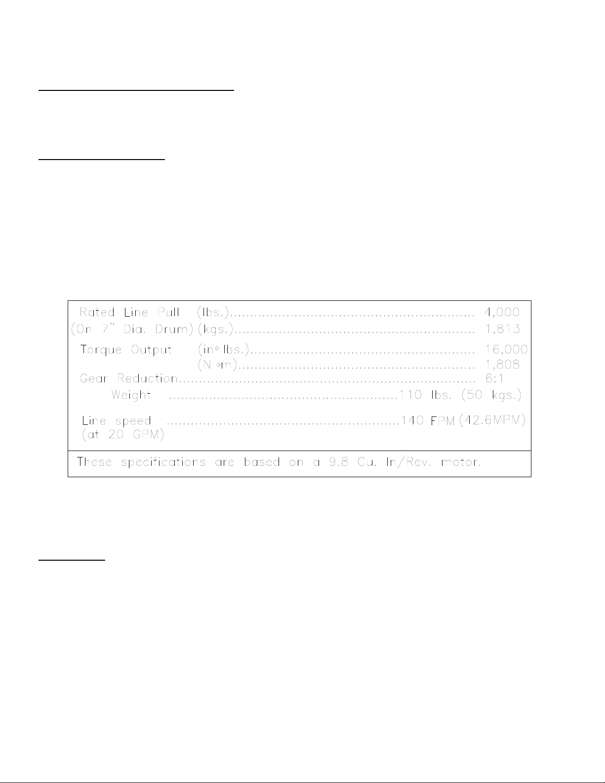
SPECIFICATIONS*
WARNINGS:
STAY OUT FROM UNDER AND AWAY FROM RAISED LOADS. FAILURE TO DO SO MAY RESULT IN
SERIOUS INJURY OR DEATH.
DO NOT EXCEED MAXIMUM LINE PULL. RATINGS SHOWN IN TABLE.
DO NOT USE CAPSTAN TO LIFT, SUPPORT, OR OTHERWISE TRANSPORT PEOPLE.
1
Page 4

CAPSTAN DRIVE MOUNTING
The drive housing has six (6) through drilled holes for 5/8 in. capscrews and four (4) holes drilled
and tapped to ¾ - 10UNC that can be used for mounting. The drive can be either flange mounted using the four holes in the face of the housing, or surface mounted using the four tapped holes. A minimum of four (4) grade 5 or better fasteners should be used.
CAPSTAN SAFEGUARDS AND OPERATION
The capstan drive is equipped with a dual brake valve cartridge; therefore, the capstan may be
operated in either direction. The rope can be wrapped around the capstan in either direction.
To install the bayonet type capstan, push the capstan onto the extension shaft, against spring tension, then turn counter-clockwise (viewed from the outside) to the stop. Release the capstan and verify that the spring has pushed the capstan outward into the lock position.
MAINTENANCE
Adhering to the following maintenance schedule will keep your capstan in top condition and performing
as it should with a minimum of repair.
A. WEEKLY
1. Check the oil level and maintain it to the oil level plug.If oil is leaking out, determine location and
repair.
2. Check the pressure relief plug in top of the gear housing. Be sure that it is not plugged.
B. MONTHLY
1. Check the capstan mounting bolts. If any are missing, replace them and securely tighten any that
are loose. Use grade 5 or better bolts.
2. Inspect the cable. If the cable has become frayed with broken strands, replace immediately.
C. ANNUALLY
1. Drain the oil from the capstan annually or more often if winch is used frequently.
2. Fill the capstan to the oil level plug with clean kerosene. Run the capstan a few seconds with no load
in the reel in direction. Drain the kerosene from the capstan.
3. Refill the capstan to the oil level plug with all purpose SAE 80W-140 gear oil.
.
2
Page 5
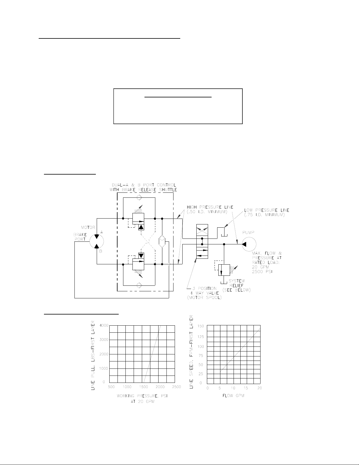
HYDRAULIC SYSTEM REQUIREMENTS
Refer to the performance charts below to properly match your hydraulic system to the capstan
performance. The charts consist of: (1) first layer line pull (LB) vs. working pressure (PSI), (2)
first layer line speed (FPM) vs. flow (GPM), and (3) relief valve setting (PSI) vs. flow (GPM). A
motor spool directional control valve is required.
SYSTEM REQUIREMENTS:
2500 PSI RELIEF VALVE SETTING
20 GPM FLOW RATE*
10 MICRON NOMINAL FILTRATION
*CAUTION: DO NOT EXCEED 20 G.P.M. IF EXCEEDED, MOTOR AND WINCH MAY BE DAMAGED
TYPICAL LAYOUT
PERFORMANCE CHARTS
PERFORMANCE WITH 9.8 CU. IN. HYDRAULIC MOTOR
3
Page 6

TROUBLE SHOOTING GUIDE
CONDITIONS POSSIBLE CAUSE CORRECTION
CAPSTAN WILL NOT
PULL MAXIMUM
LOAD
SLOW LINE SPEED
EXCESSIVE NOISE
1. System relief valve may be set too
low
2. Low Hydraulic Oil
1. Relief valve may be clogged
2. Low Hydraulic Oil
3. Low Hydraulic System Flow rate.
4. Motor worn out
1. Hydraulic system flow too high
1. Increase relief valve setting until
recommended pressure is obtained.
2. Check/Fill oil in reservoir
1. Remove/Clean relief valve.
Re-Install valve and reset pressure
2. Check/Fill reservoir
3. Check flow rate. Refer to Page 3
Hydraulic system requirements.
4. Replace motor
1. Check flow rate. Refer to Page 3
Hydraulic system requirements.
4
Page 7

INSTRUCTIONS FOR OVERHAUL 16K CAPSTAN
Take note of mounting configurations for proper mounting of parts during re-assembly. Replace all gaskets, orings, and seals during re-assembly.
Disconnect tube (item #40) from elbow fittings (items #20) on bottom of end bearing and counterbalance valve
(item #19). Remove motor (item #11) from end bearing by slowly unscrewing capscrews (items #38). CAUTION:
MOTOR IS UNDER SPRING PRESSURE.
Remove springs (items #18) from pockets and inspect for damage.
Replace gasket (item #17).
Remove coupling and input shaft (item #4 and #5) from end bearing. Examine coupling for signs of wear, replace
if necessary. If necessary, remove counterbalance valve from motor by removing capscrews (items #39).
38
20
11
17
40
18
19
5
4
39
20
5
Page 8

Remove retaining rings (items #27 and 35) with screwdriver.
Remove brake parts from end bearing. NOTE POSITION OF O-RINGS AND BACKUP RINGS BEFORE REMOVAL. Examine brake discs (items #6) and stators (items #8) for signs of wear, and replace if necessary.
Examine o-rings (items #29 and 30) and backup rings (items #32 and 34) in brake piston (item #3), as well as oring
(item #31) and backup ring (item #33) in backup brake piston (item #7) for signs of wear. Remove o-rings
and backup rings from grooves in brake piston or backup brake piston and replace if necessary.
35
32
27
30
7
3
6
29
34
31
33
8
6
Page 9

Remove the carrier assembly (item #2), input coupling (item #10), and retaining ring (item #26).
Remove ring gear (item #12) and dowel pins (item #15).
Using a screwdriver, remove the retaining rings (item#25) from the gear housing (item #1)
Remove pin (item #14) from output shaft (item#9)
Using a soft hammer, gently tap the output shaft (item#9) from housing (item #1).
Bearings (item #23) can be removed from output shaft (item #9) by removing retaining rings (item #24)
Oil seal (item #21) should be inspected and replaced if necessary.
15
12
2
10
24
9
26
25
14
25
23
23
22
24
24
36
37
22
21
1
22
7
Page 10

Set winch with gear housing end down on work surface.
Install well-oiled o-rings and backup rings into grooves on outside of brake piston and backup brake piston as shown
in cross-section A-A below.
Piston, backup piston, brake discs and stators must be clean and free of grease and oil.
Insert brake discs (item #6) and stators (item #8) into gear end alternating, with stators first and last.
Insert backup brake piston (item #7) into motor end and insert brake piston (item #3) into it. Apply even pressure
on piston when installing.
Install retaining rings (item #27 and 35) into grooves in motor end housing. NOTE: (Item #27) is thicker than
(item #35)
31
MOTOR SIDE
32
30
29
33
34
27
3
35
29
32
34
30
31
HOUSING SIDE
7
3
SECTION A-A
7
6
33
8
8
Page 11

Insert springs (item #18) into pockets in back of brake piston.
Insert motor coupling (item #4) , engaging it with input shaft (item #5).
Place gasket (item #17) on mounting surface of motor (item #11). Slide motor shaft into coupling. Attach motor to
motor end bearing housing using (2) capscrews (item #38). Evenly tighten to 49 ftlbs. (66 Nm) torque.
Install the counterbalance valve (item #19) to the motor using (4) capscrews (item #38). Tighten to 17 ft-lbs (23 Nm).
Securely connect fittings (item #20) to motor end housing and counterbalance valve, and connect tube assembly
(item #40) to fittings.
Apply at least 550 PSI hydraulic system pressure to brake and verify that brake releases.
38
20
11
17
40
18
19
5
4
39
20
9
Page 12

DISASSEMBLY OF CARRIER ASSEMBLY
Carrier assemblies may be purchased as a complete assembly (see pg.16 ) or parts may be
purchased individually (see pg 13). If purchasing individual parts, it will be necessary to
disassemble the gear carrier as outlined below.
1. Carefully drive roll pin #103 into carrier pin #102 so that it is captured within carrier pin #102
but not touching the opposite side of the carrier #101.
2. Tap carrier pin #102 to remove it from the carrier #101.
3. Remove planet gear assembly#104 from the carrier #101.
4. Remove the roll pin #103 from the carrier pin #102.
5. Repeat this process for the two remaining gears in the carrier.
104
103
101
ITEM QTY PART NO DESCRIPTION
101 1 317024 CARRIER-INPUT MACHINED CAPSTAN
102 3 470134 PIN INPUT PLANET CARRIER 16K CAPSTAN
102
103 3 470060 ROLL PIN 3/16 DIA. X 7/16 LG
104 3 296706 GEAR INPUT PLANET ASSEMBLY 16K CAPSTAN
10
Page 13

8.5
0
4.25
8.50
5.50
7.16
3.58
3.58
7.16
4x Ø0.65
Ø4.75
3.38
Ø2.44
2.55
Ø0.75
7.75
DRAIN PORT
5.63
24.80
0.69
17.05
VENT/FILL PORT
LEVEL PORT
(BOTH SIDES)
3/4-10UNC-2B X
1.25 DEEP 4-PLACES
4.25
5.64
8.50
11
Page 14
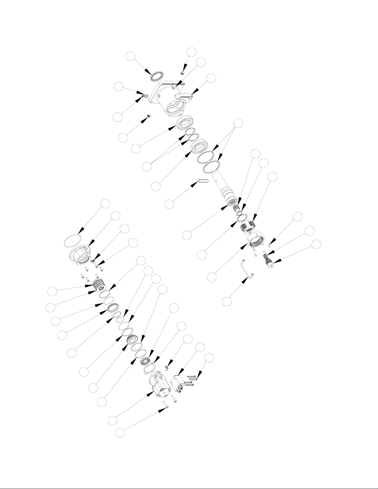
37
21
22
1
22
36
25
22
23
10
24
26
2
23
28
16
20
13
14
15
9
4
5
24
33
29
30
6
27
12
8
18
40
31
17
7
20
19
34
39
32
3
35
11
38
12
Page 15

1 1 338376 HOUSING-GEAR, MACHINED, 23 2 402130 BEARING-BALL, 6215-SKF
2 1 247044 CARRIER ASSEMBLY-INPUT 24 3 490064 RING-RETAINING, DNH-130
PARTS LIST
ITEM QTY PART NO DESCRIPTION ITEM QTY PART NO DESCRIPTION
3 1 330013 PISTON-BRAKE, MACHINED, 25 2 490063 RING-RETAINING, DNS-75
4 1 355146 SHAFT-INPUT 1 26 1 490055 RING-RETAINING, DNS-42
5 1 431034 COUPLING-MOTOR 27 1 490066 RING-INTERNAL RETAINING
6 5 330012 DISC-BRAKE 28 1 462079 O-RING-5.234 ID X .139 DIA
7 1 330014 PISTON-BACKUP BRAKE, MACHINED 29 1 462067 O-RING-2.225 ID X .210 THK
8 6 330011 STATOR-BRAKE, 30 1 462068 O-RING-3.10 ID X .210 THK
9 1 355143 SHAFT-OUTPUT, 31 1 462069 O-RING-2.975 ID X .210 THK
13
10 1 431025 COUPLING-INPUT CARRIER 32 1 462070 RING-BACKUP, 3.143 ID X .076 THK
11 1 458178 MOTOR-HYD 9.8 C.U.IN. 33 1 462071 RING-BACKUP, 3.018 ID X .076 THK
12 1 334827 RING GEAR 34 1 462072 RING-BACKUP, 2.268 ID X .076 THK
13 6 414897 CAPSCREW-3/8-16NC X 1LG,SOCKET HEAD 35 1 490049 RING-INTERNAL RETAINING
14 1 470106 PIN-CAPSTAN SHAFT 36 1 456008 RELIEF FIT-1/8-27PFT,BALL CHECK,Z/P
15 5 424035 PIN-DRUM DRIVE 37 1 468042 REDUCER-3/4-16 O-RING X 1/8NPTF
16 1 338375 HOUSING-BRAKE, MACHINED 38 2 414511 CAPSCREW-1/2-13 X 2.0 LG SOC HD
17 1 442223 GASKET-MOTOR FLANGE 39 4 414159 CS-5/16-18UNCX2.50,HXHD,GR5,ZP,N/P
18 11 494124 SPRING-BRAKE 40 1 509134 ASSEMBLY-TUBE, HYD BRAKE RELEASE
19 1 516013 VALVE-MTR CONTROL
20 2 432018 FITTING Parker#4-C5OX-S T-LOK, 7/16-20 90 degree
21 1 486086 SEAL-OIL
22 3 468041 PLUG-3/4-16 (-8 SAE) WITH O-RING, SOC HD
Page 16

RAMSEY WINCH warrants each new RAMSEY Winch to be free from defects in material and
workmanship for a period of one (1) year from date of purchase.
The obligation under this warranty, statutory or otherwise, is limited to the replacement or repair at
the Manufacturer's factory, or at a point designated by the Manufacturer, of such part that shall
appear to the Manufacturer, upon inspection of such part, to have been defective in material or
workmanship.
This warranty does not obligate RAMSEY WINCH to bear the cost of labor or transportation charges
in connection with the replacement or repair of defective parts, nor shall it apply to a product upon
which repair or alterations have been made, unless authorized by Manufacturer, or for equipment
misused, neglected or which has not been installed correctly.
RAMSEY WINCH shall in no event be liable for special or consequential damages. RAMSEY WINCH
makes no warranty in respect to accessories such as being subject to the warranties of their
respective manufacturers.
RAMSEY WINCH, whose policy is one of continuous improvement, reserves the right to improve its
products through changes in design or materials as it may deem desirable without being obligated to
incorporate such changes in products of prior manufacture.
If field service at the request of the Buyer is rendered and the fault is found not to be with RAMSEY
WINCH's product, the Buyer shall pay the time and expense to the field representative. Bills for
service, labor or other expenses that have been incurred by the Buyer without approval or
authorization by RAMSEY WINCH will not be accepted
See warranty card for details.
RAMSEY WINCH COMPANY
PO BOX 581510
Tulsa OK 74158-1510
Telephone: (918) 438-2760
FAX: (918) 438-6688
Visit us at www.ramsey.com
914231-0409-A
 Loading...