


VIPER TOOL
OPERATOR’S
SAFETY & OPERATING
INSTRUCTION MANUAL
DANGER
THIS TOOL FOR USE BY LICENSED OPERATORS ONLY.
READ AND OBEY ALL SAFETY AND OPERATING
INSTRUCTIONS BEFORE OPERATING TOOL.
SEMI-AUTOMATIC, LOW VELOCITY
PISTON TYPE FASTENING TOOL

Just as no one can merely read a book about driving an automobile and then hope
to drive one safely, no one should attempt to use any Ramset tool without adequate,
competent personal instruction. And just as one must be licensed to drive an automobile,
one must also be licensed to use a powder actuated tool. No automobile instruction
book or instructor can forewarn a learner against all possibilities and emergencies, nor
can Ramset instructors and printed material detail all possible conditions surrounding
the use of Ramset tools and products.
Responsibility for the safe and proper use of this tool rests with the tool user
and the employer.
SAFETY INTRODUCTION
DANGER
SAFETY INTRODUCTION
DANGER
2
Operator’s and bystanders
must wear eye and hearing
protection.
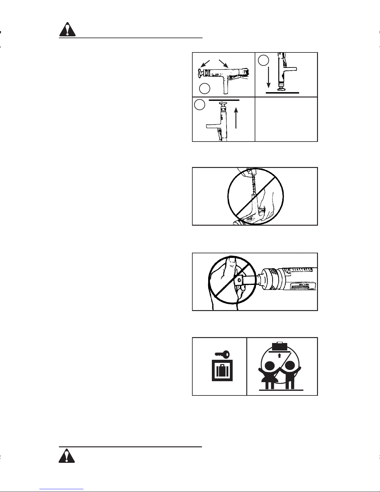
Never close tool with hand over fastener loading end of the tool.
A serious hand injury from penetration by the piston or a
discharged fastener could result.
Read manual before
operating tool.
DANGER
THIS TOOL IS TO BE USED ONLY BY PROPERLY TRAINED
AND LICENSED OPERATORS.
YOU MUST SUCCESSFULLY COMPLETE THE
RAMSET TRAINING PROGRAM FOR THE
TOOL AND OBTAIN A CERTIFIED OPERATOR’S LICENSE
BEFORE HANDLING, LOADING OR OPERATING THIS TOOL.
ATTEMPTING TO HANDLE OR OPERATE THIS TOOL
WITHOUT PROPER TRAINING AND LICENSING CAN RESULT IN
SERIOUS INJURY TO THE OPERATOR OR BYSTANDERS.
DANGER

Preparation
Acceptable Base Materials
Powder actuated fastening is suitable for
use in the following base materials only:
• PouredConcrete
• StructuralSteel
• MasonryJoints(seepage8)
Never attempt to fasten into any other
type of material.
Fastening into other
materials can cause blindness or other
serious injury.
Unacceptable Base Materials
Never attempt to fasten into very hard or
brittle materials such as cast iron, tile,
glass, or rock of any type. These materials
can shatter, causing the fastener and/or base
material fragments to fly free and cause
serious injury to the tool operator and others.
Never fasten into soft base materials, such as
drywall or lumber products.
These materials
may allow the fastener to travel completely
through and out the other side, endangering
those in the path of the fastener.
Never fasten into any base material that
does not pass the Center Punch test.
Failure to assure the suitability of the base
material can result in serious injury to the
eyes or other body parts.
Center Punch Test
ALWAYS WEAR SAFETY GOGGLES
WHEN PERFORMING THIS TEST.
1. Always check the material being
fastened into for hardness before
attempting any fastening operation.
2. Using a fastener as a center punch,
strike the fastener against the work
surface using an average hammer
blow and check the results.
Center Punch Test Results
1. If the fastener point is flattened,
the material is too hard for a
powder actuated fastening.
2. If the fastener penetrates the
material easily, the material is
too soft.
3. If the material cracks or shatters,
the material is too brittle.
4. If the fastener makes a small
indentation into the material, the
material is suitable for fastening.
DANGER
SAFETY INSTRUCTIONS
SAFETY INSTRUCTIONS
DANGER 3
NEVER FASTEN INTO VERY HARD OR
BRITTLE MATERIALS
NEVER FASTEN INTO SOFT MATERIALS
SUCH AS DRYWALL
Preparación
Materiales base aceptables
La fijación por medio de herramientas
activadas con pólvora es solamente
adecuada para usarse en los siguientes
materiales base:
•Concretovertido
•Aceroestructural
•
Nunca intente realizar las fijaciones en
otro tipo de material.
materiales puede ocasionar ceguera u
otras lesiones graves.
Materiales base inaceptables
Nunca intente realizar las fijaciones en
materialesmuydurosofrágilestales
comohierrofundido,cerámica,vidrio,o
piedra de cualquier tipo.
se pueden hacer pedazos, haciendo que
los fragmentos del material base o del
elemento de fijación salten y ocasionen
lesiones graves al operador de la
herramienta y a terceros.
Nunca fije los elementos sobre materiales
base blandos, tales como paredes de yeso
o productos de madera. Estos materiales
pueden permitir que el elemento de fijación
los atraviese completamente y salga por
el otro lado, poniendo en peligro a aquellos
que se encuentren en el paso del elemento
de fijación disparado.
Nunca realice las fijaciones en un material
base que no pase la prueba de Punzón
de Marcar.
del material base puede ocasionar lesiones
graves a los ojos y a otras partes del cuerpo.
Prueba de Punzón de Marcar
USE SIEMPRE GAFAS DE SEGURIDAD
CUANDO REALICE ESTA PRUEBA.
1. Compruebe siempre la dureza del
2.

Loads & Load Selection Safety
1. Always make a test fastening after
being sure that the base material
is suitable for powder actuated
fastening. Failure to determine the
correct power level to be used may
result in the use of excessive power,
allowing the fastener to pass completely
through the work material, causing
serious or fatal injuries to others who
may be in the path of the fastener.
2. Color-blind operators must always
select loads by number to prevent
use of an incorrect load for the same
reasons as in #1 above.
Workplace Safety
1. Operators and bystanders must
always wear approved eye protection
and approved hearing protection.
Failure to do so may result in blindness
or serious eye injury from flying debris
and loss of hearing from constant or
repeated unprotected exposure to
fastening noise.
2. Always keep the work area clear of
bystanders and unnecessary materials
that could interfere with safe tool
operation. Operating the tool in a
congested or cluttered area may affect
your ability to operate the tool safely.
3. Never operate tool if flammable
or explosive materials are nearby.
Powder loads burn and create sparks
when fired and could ignite these
materials or fumes.
4. Always post warning signs within
50 ft. of the area where fastening
is to be done. Sign must state:
“WARNING - Powder Actuated
Tool In Use”. Failure to warn others
may result in serious injury to them.
Contact Ramset at 1-800-241-5640
to obtain this sign.
SAFETY INSTRUCTIONS
DANGER
SAFETY INSTRUCTIONS
DANGER
4
ALWAYS MAKE A TEST FASTENING
COLOR-BLIND OPERATORS MUST
ALWAYS SELECT LOADS BY NUMBER
KEEP WORK AREA CLEAR OF
BYSTANDERS AND CLUTTER
NEVER OPERATE THE TOOL AROUND
FLAMMABLE OR EXPLOSIVE MATERIALS
WARNING
POWDER
ACTUATED
TOOL IN USE
WITHIN 50 FEET
Safety is important – Take proper precautions.
ALWAYS POST WARNING SIGNS
Tool Handling Safety
1. Always be sure tool is operating
properly before attempting to use
it. Follow the “Daily Function Test”
shown to the right and described
on page 9.
2. Always load tool using a strip load
selected directly from a box indicating
the power load type and number.
Never attempt to use loose strip
loads that could be mis-identified.
3.
Never carry loose loads in pockets
with pins or other hard objects.
4. Never load a tool unless you intend
to immediately make a fastening.
Loading a tool and leaving it unattended
in the work area can result in the tool
being accidentally discharged by others.
5. Never place your hand or any other
body part over the fastener loading
end of the tool. Serious hand injury
could result from being struck by either
a fastener or the tool piston should the
tool be accidentally fired.
6. Always store the tool unloaded and
keep the tool and the loads securely
locked in a tool box. Keep keys away
f
rom children and unlicensed persons.
7. Always keep the tool pointed away
from yourself and others.
8.Nevercarryaloadedtoolaround
the work area.
9. Never allow anyone not trained
to use the tool.
10. Never engage in horseplay with
the tool.
11. Using the tool in poorly ventilated
areas, cleaning tool or handling
loads may result in exposure to
lead or other substances known
to cause birth defects, and other
physical harm. Have adequate
ventilation at all times and wash
thoroughly after exposure.
DANGER
SAFETY INSTRUCTIONS
SAFETY INSTRUCTIONS
DANGER 5
NEVER LOAD THE TOOL UNLESS IT IS
TO BE USED IMMEDIATELY
NEVER PLACE HANDS OR BODY OVER
MUZZLE OPENING
KEEP TOOL LOCKED & OUT OF THE
REACH OF CHILDREN
A
B
C
Seguridad en el manejo de la
herramienta
1. Compruebe siempre que la herramienta
2.
3.
4. Nunca cargue una herramienta a menos
5. Nunca coloque la mano ni ninguna otra
6.
7. Mantenga siempre la herramienta
8. Nuncatransporteunaherramienta
9. Nunca permita que personas sin
10.
11. La utilización de la herramienta, limpiarla
Empty
CHECK
OPERATION
DAILY
ALWAYS DO A DAILY FUNCTION TEST
BEFORE LOADING TOOL

FAILURE TO FOLLOW
INSTRUCTIONS CAN
CAUSE INJURY TO THE
TOOL OPERATOR OR
TO BYSTANDERS.
Fastener Driving Safety
1. Only use the tool for fastening into
a suitable base material.
2. Never fire the tool without a fastener.
Firing a tool without a fastener will
cause the piston to strike the work
surface, and may cause serious injury
to you and others in the work area.
3. Always use the spall guard whenever
possible to minimize flying particles
or debris.
4. Always hold the tool perpendicular
to and firmly against the work
surface
when making a fastening.
Failure to do
so could allow a fastener
to ricochet.
5. Never attempt to drive a fastener
close to an edge or to another
fastener. See page 8 for guidelines.
ALWAYS FOLLOW THE
MISFIRE PROCEDURE.
If the tool does not fire after the normal
firing sequence, continue to hold the
depressed tool against the work surface
for at least 30 seconds. Then carefully lower
the tool, remove the strip load, and put it
in a can of water or other non-flammable
liquid. Never carelessly discard a strip with
live loads into a trash container.
If the tool becomes stuck or jammed with
a live powder load,
keep the tool pointed
in a safe direction, and immediately tag it,
“Danger- defective - do not use”.
Lock
the tool in a tool box and call your local
Ramset distributor for assistance.
SAFETY INSTRUCTIONS
DANGER
SAFETY INSTRUCTIONS
DANGER
6
USE SPALL GUARD WHENEVER POSSIBLE
ALWAYS HOLD THE TOOL
PERPENDICULAR TO THE WORK SURFACE
NEVER DRIVE A FASTENER CLOSE TO
AN EDGE
HOLD THE TOOL FIRMLY AGAINST
THE WORK SURFACE FOR AT
LEAST 30 SECONDS
SPALL
GUARD
90°

Your Ramset Viper Tool uses only the Ramset fasteners and loads shown below or
listed for the tool in the Product Catalog.
FASTENERS AND FASTENER ASSEMBLIES
CEILING CLIP ASSEMBLIES - .300 HEAD DIA.
CAT. NO. SHANK DIA. LENGTH
SDC100 .145 1”
SDC125 .145 1-1/4”
SPC78* .150PowerPoint 7/8”
SPC114* .150/.180PowerPoint 1-1/4”
Note:*ForHardConcrete
FASTENERS / LOADS
FASTENERS / LOADS
7
Never use any other types of fasteners or strip loads in the Viper Tool. Use of other types
of fasteners or loads may cause unintentional load discharge, damage the tool, cause poor
fastening performance, or create a risk of serious injury to the operator or bystanders.
DANGER
LOADS
Ramset RS 27 strip loads are specially made for use in the Viper Tool.
The power level of the load is indicated by
the number marked on each box, the color
of the box, and the color on the tip of each load. As the number increases, the power
level also increases.
Always perform the center punch test
described on page 3 to test the base material.
Always make a test fastening using the lowest power level first. If more power is
required to set the fastener, use the next higher power level until the power level
necessary to drive the fastener is reached.
RS 27 10 SHOT STRIP LOAD
POWER CATALOG LOAD CASE
LEVEL NUMBER COLOR COLOR
2 2RS27 Brown Brass
3 3RS27 Green Brass
4 4RS27 Yellow Brass
5 5RS27 Red Brass
CARGAS
LastirasdecargasRS27estánespecialmentefabricadasparausarseconla
herramienta Viper.
Elniveldepotenciadelascargasestáindicadoporelnúmeromarcadoencadacaja,elcolor
de la caja y el color de la punta de cada carga. A medida que aumenta el número, también
aumenta el nivel de potencia de la carga.
Realice siempre la prueba de Punzón de Marcar
base.
Realice siempre una fijación de prueba usando
bajo.
potencia hasta
elemento.
Su herramienta Ramset Viper utiliza solamente elementos de fijación y cargas Ramset
comolosquesemuestranacontinuaciónoenelcatálogodeproductos.
ELEMENTOS DE FIJACÍON Y CONJUNTOS DE ELEMENTOS DE FIJACÍON
CAT. NO. DIA. VÁSTAGO LARGO
SDC100 .145 1 pulg.
SDC125 .145 1-1/4 pulg.
SPC78* .150PowerPoint 7/8pulg.
SPC114* .150/.180PowerPoint 1-1/4pulg.
Nota:*Paraconcretoduro

FASTENING APPLICATIONS
Your Ramset tool can be used for a wide
range of fastening needs in a variety of
base materials. Reading and follow these
important fastening guidelines will help you
get the best results from your tool, fasteners,
and powder loads, as well as help you
perform these fastening operations safely
and effectively.
Powder actuated fastenings are permanent
fastening so attempting to remove a fastener
from concrete or steel may result in serious
injury.
Fastening to Concrete
When fastening into concrete, always
maintain a minimum spacing of 3”
between fastenings
and 3” from any free
edge. Concrete thickness
should be at
least three times the intended penetration
depth into the concrete.
Driving fasteners too close to an edge or too
close to each other can cause the concrete
edge to fail or fasteners to fly free.
Fastening to Steel
Your Ramset tool can be used for fastening
on the flat surfaces of structural steel.
When fastening into steel, always maintain
a minimum spacing of 1-1/2” between
fastenings and 1/2” from any edge.
FASTENING APPLICATIONS
FASTENING APPLICATIONS
8
SPACING — FASTENING INTO CONCRETE
FASTENER LOCATIONS IN
LIGHTWEIGHT PAN DECK
SPACING IN STEEL
3”
3”
FASTENER LOCATION IN
PRECAST CONCRETE
PENETRATION INTO CONCRETE
3 x P
MIN.
P
1-1/2”
MIN.
1/2”
MIN.
MíN
1/2
pulg.

TOOL OPERATION
DAILY FUNCTION TEST
Always check the tool first to make sure
that it does not contain a load strip or
fastener. Test the tool overhead several
times by completely depressing it on a hard
surface. You should hear an audible click as
the firing pin releases. Let up on the
tool and
check to be sure that the barrel assembly
has opened to the starting position.
Next, place the tool, pointing downward, on
a hard surface and firmly, completely depress
the tool. You must not hear the firing pin
release! If the firing pin releases.
STOP, DO
NOT TRY TO USE THE TOOL UNTIL THE
PROPER REPAIRS HAVE BEEN MADE.
Contact your Ramset Distributor for repairs.
OPERATING THE VIPER TOOL
1. Insert a fastener assembly into the
muzzle bushing end of the tool until
it is fully seated. If a clip assembly is
being used, be sure it is positioned in
the cutout section of the spall guard.
2. Insert a load strip into the bottom of the
handle and push it in until your finger is
in firm contact with the handle recess.
Never try to insert a load strip into the
tool from the top of the receiver.
3. Carefully raise the tool to the ceiling
and depress the barrel assembly
where the fastening is to be made.
Hold the tool perpendicular and forcibly push upwards on the pole handle
to compress the firing pin spring and
release the sear to fire the tool. If the
tool does not fire, continue to hold it
in place for at least 30 seconds and
then follow the misfire procedure on
page 6. Always point the tool in a safe
direction and use care when raising it
to the ceiling to avoid bumping objects
that could cause the tool to fire.
TOOL OPERATING INSTRUCTIONS
TOOL OPERATING INSTRUCTIONS
9
INSERT FASTENER INTO THE MUZZLE END
OF THE TOOL
INSERT LOAD STRIP INTO THE OPENING IN
THE BOTTOM OF THE HANDLE
RAISE TOOL TO THE CEILING AND DEPRESS
THE BARREL ASSEMBLY. THEN PUSH UP
FORCIBLY AGAINST THE WORK SURFACE
TO FIRE THE TOOL
PERFORM FUNCTION TEST WITH EMPTY,
UNLOADED TOOL
A
B
C
Empty
CHECK
OPERATION
DAILY
FUNCIONAMIENTO DE
LA HERRAMIENTA
Prueba diaria de funcionamiento. Siempre
compruebe primero la herramienta para
cerciorarse de que no contenga una tira
de cargas o elementos de fijación. Pruebe
la herramienta varias veces elevándola y
presionándola sobre una superficie dura.
Debe oírse un clic en el momento en que
se desengancha el percutor. Retire la
herramienta y compruebe que la boquilla
se ha abierto a la posición de comienzo.
A continuación, coloque la herramienta,
apuntando hacia abajo, sobre una superficie
dura y oprímala con firmeza para hacer que
se retraiga completamente.
el desenganche del percutor! Se el percutor se
desengancha, DETÉNGASE, NO INTENTE
UTILIZAR LA HERRAMIENTA HASTA
QUE
APROPIADA.
distribuidor Ramset para estas reparaciones.
OPERACIÓN DE LA
HERRAMIENTA VIPER
1. Inserte un conjunto de elementos de fijación
2. Inserte una tira de cargas en la parte
3. Levante cuidadosamente la herramienta
DE LA HERRAMIENTA 9
90°

4. Lower the tool, keeping it pointed in
a safe direction, and insert the next
fastener or fastener assembly. Note:
While the Viper tool is being closed and
fired, the advance lever cam has caused
the load advance lever to be indexed
downward to pick up the next load.
When the tool is lowered and opens
up, the next unfired load is indexed
upward to the firing position. At the
same time, as the tool is lowered, the
piston is automatically reset for the
next fastening.
NEVER PLACE YOUR HAND OR
FINGERS OVER THE MUZZLE
BUSING WHILE AN UNFIRED LOAD
IS IN POSITION TO BE FIRED.
5. After all 10 loads in the strip have been
fired, pull the used load strip from the
top of the tool. NEVER try to pull a load
strip from the bottom of the tool.
6. If you are working in an area where
dirt or debris can fall onto the tool
while making fastenings, check the
tool frequently to be sure the muzzle
bushing and loads strip track are clear.
NOTE: Use of partially used load strips.
The design of the Viper tool is such that
the next load to be fired is automatically
indexed into the firing position during
the tool closing, firing and tool opening
sequence of operation. If it is necessary
to use a partially used load strip, the
end of the strip containing the live loads
should be placed into the bottom of the
tool handle just as if it were a new strip.
By counting the number of unfired loads
in the strip before inserting it and keeping
count as the fastenings are being made,
one can easily determine when all of the
loads have been used.
SHOULD YOU DECIDE NOT TO MAKE A
FASTENING AFTER THE TOOL HAS BEEN
LOADED, ALWAYS REMOVE THE POWDER
LOAD FIRST, THEN THE FASTENER. THIS
WILL PREVENT ACCIDENTAL DISCHARGING
OF THE FASTENER OR PISTON INTO THE
OPERATORS HAND.
TOOL OPERATING INSTRUCTIONS
TOOL OPERATING INSTRUCTIONS
10
INSERT THE NEXT FASTENER OR
FASTENER ASSEMBLY INTO THE
MUZZLE BUSHING
REMOVE THE LOAD STRIP FROM THE TOP
OF THE TOOL
CHECK THE MUZZLE BUSHING AND
LOAD STRIP TRACK FOR DEBRIS

REFER TO PARTS SCHEMATIC FOR PROPER ASSEMBLY OF PARTS
– Overdriving of fasteners – Excessive power – Change to the next lower power
level load color and number.
– Soft base material – Check base material (see page 3)
– Tool fails to fire – Failure to depress – See “Tool does not completely
completely depress”
– Excessive dirt buildup on – After following misfire procedure,
breech face not allowing check firing pin indentation on
proper penetration of load. Clean breech face.
firing pin
– Firing pin and/or firing pin – Replace damaged parts
assembly damaged
– Tool does not completely – Misassembled or – Check all parts in the receiver for
depress damaged parts damage or improper assembly.
– Reduction or loss of power – Piston not being returned – Disassemble and clean barrel,
to the full rear position piston and nosepiece
– Worn or damaged piston – Replace damaged piston
– Failure to index strip – Strip not inserted in tool – Check load strip. Properly
correctly or is damaged dispose of damaged strip.
(See page 6)
– Damaged indexing – Contact your Ramset
mechanism Distributor for assistance
– Tool fails the – Contact your Ramset
Daily Function Test Distributor for assistance
TROUBLESHOOTING
TROUBLESHOOTING
11
CONSULTE EL DIAGRAMA DE PIEZAS PARA ARMAR CORRECTAMENTE LAS MISMAS
- Penetración excesiva - Potencia excesiva - Cambie la tira de cargas al número y
de elementos color de nivel de potencia anterior.
de fajación
- Material base blando - Verifique el material base
(vea la página 3).
- La herramienta - No se contrae completamente - Vea el párrafo “La herramienta
no dispara no se contrae completamante”.
- La acumulación excesiva - Después de haber completado
de suciedad en la cara de el procedimiento de falla de disparo,
la recámara no permite compruebe la marca del percutor
la penetración correcta sobre la carga. Revise la cara de
del percutor. la recámara
- EI percutor o la recámara - Reemplace las piezas dañadas
están dañados
- La herramienta - Piezas mal armadas o dañadas - Revise todas las piezas del
no se contrae receptor para buscar daños o
completamente armado incorrecto
- Reducción o pérdida - EI pistón no se retrae - Desarme y limpie el cañón el pistón
de potencia hasta su posición trasera total y la boquilla
- Pistón desgastado o dañado - Reemplace el pistón dañado
- Falla en la colocación - La tira no se insertó - Revise la tira de cargas. Deseche
tira de cargas correctamente en la correctamente la tira dañada (vea la
herramienta no esá dañada página 6).
- El mecanismo de avance - Comuníquese con su distribuidor
está dañado Ramset para obtener ayuda
La herramienta no pasa - Comuníquese con su distribuidor
la prueba diaria de Ramset para obtener ayuda
funcionamiento

PARTS SCHEMATIC
PARTS SCHEMATIC
12

PARTS LIST / MAINTENANCE
PARTS LIST / MAINTENANCE
13
Always make sure the tool is not loaded before performing any service or repair and
always wear safety goggles when cleaning or servicing the tool.
DAILY CLEANING
All front end parts shown in the disassembly section are to be cleaned daily with a good
detergent oil and wire brush. Remove all dirt and carbon buildup and wipe parts dry with
a clean rag. Check all parts for wear or damage before reassembly and replace or repair
any worn or damaged parts.
PERIODIC COMPLETE CLEANING / GENERAL MAINTENANCE
Heavy or constant exposure to dirt and debris may require that the tool be cleaned more
extensively. Complete disassembly and cleaning of all parts may be necessary to restore
the tool to normal operation. General maintenance should be performed every six months
or more often if the tool is subjected to heavy use. General maintenance/complete cleaning should be done by a qualified repair person.
IMPROPERLY MAINTAINED TOOLS CAN CAUSE SERIOUS INJURIES
TO TOOL OPERATOR AND BYSTANDERS
CLEAN TOOL DAILY
ALWAYS FUNCTION TEST THE TOOL AFTER PERFORMING ANY
SERVICE. SEE PAGE 9 FOR DETAILS ON THE FUNCTION TEST.
MAINTENANCE
VIPER TOOL PARTS LIST
KEY PART NO. DESCRIPTION
1 MVP100A MUZZLE BUSHING ASSEMBLY
2 MVP140 PISTON
3 MVP150 BARREL
4 MVP21A SPRINGS (barrel, firing pin & firing pin assembly)
5 MVP110A BUFFER (PKG of 3)
6 MVP101 HOUSING
7 2VP18 FIRING PIN ASSEMBLY
8 MVP500AP ADVANCE LEVER AND PIN
9 MVP600A ADVANCE LEVER CAM AND SCREW
10 MVP028 POLE CONNECTOR
11 2VP11 LOCKOUT BALL (PKG. OF 3)
12 2VP29 HANDLE CONNECTOR
13 MVP130 RETAINING COLLAR
14 MVP30 SPALL GUARD
15 2VP33 WAVE WASHER
16 MVP001A LINER BALLS AND SPRINGS (not shown)
17 316540 PAWLS (PKG of 2)
Verifique siempre que la herramienta no esté cargada antes de realizar cualquier operación de servicio
o reparación y utilice siempre gafas de seguridad cuando esté limpiándola o dándole servicio.
LIMPIEZA DIARIA
Todas las piezas del extremo anterior mostradas en la sección de desarmado se deben limpiar
diariamente con un buen aceite detergente y un cepillo de alambre. Elimine la acumulación
de suciedad y carbón y seque las piezas con un paño limpio. Revise el desgaste o el daño de
todas las piezas antes de volver a armar la herramienta y reemplace o repare cualquiera que se
encuentre desgastada o dañada.
LIMPIEZA COMPLETA PERIÓDICA / MANTENIMIENTO GENERAL
El uso continuo o la exposición constante a suciedad o los desechos puede requerir que la
herramienta se limpie más exhaustivamente. Puede ser necesario desarmarla completamente y
limpiar todas las piezas para restaurar la herramienta a su condición normal. El mantenimiento
general se debe realizar cada seis meses o más frecuentemente si la herramienta se usa
intensamente. El mantenimiento general y la limpieza completa los deberá hacer personal de
reparación calificado.
MANTENIMIENTO
LISTA DE PIEZAS DE LA HERRAMIENTA RAMSET VIPER
CLAVE No. DE PIEZA DESCRIPCIÓN
1 MVP100A CONJUNTO DEL MANGUITO EN LA BOCA
2 MVP140 PISTÓN
3 MVP150 CAÑÓN
4 MVP21A RESORTES (DEL CAÑÓN, DEL PERCUTOR Y DEL
CONJUNTO DEL PERCUTOR)
5 MVP110A SEPARADOR (PAQ. DE 3)
6 MVP101 BASTIDOR
7 2VP18 CONJUNTO DEL PERCUTOR
8 MVP500AP PALANCA DE AVANCE Y PASADOR
9 MVP600A PALANCA DE AVANCE Y TORNILLO DE LA LEVA
10 MVP028 CONECTOR DE LA CULATA
11 2VP11 ESFERA DE BLOQUEO (PAQ. DE 3)
12 2VP29 CONECTOR DEL MANGO
13 MVP130 COLLARÍN DE RETENCIÓN
14 MVP30 GUARDA DE PROTECCIÓN CONTRA ASTILLAS
15 2VP33 ARANDELA ONDULADA
16 MVP001A ESFERAS Y RESORTES DEL TUBO DE ÁNIMA (NO ILUSTRADO)
17 316540 RETENES (PAQ. DE 2)

DISASSEMBLY
14
DISASSEMBLY
TOOL DISASSEMBLY
1. Unscrew and remove the barrel
retention collar. Handle the tool
carefully after the collar is
unscrewed to prevent the two
barrel pawls from falling out.
2. Remove the two pawls from the slots
on either side of the tool housing.
3. Slide the barrel assembly and the barrel
spring out of the tool body. Note the
position of the slots on the sides of the
barrel since the tip ends of the pawls are
inserted into the barrel slots through the
tool housing in re-assembly.
4. Unscrew the muzzle bushing assembly
from the barrel. If this is difficult to do
by hand, grasp the barrel and use a
wrench on the flats of the muzzle
bushing assembly to loosen it for
complete removal.
5. Remove the piston from the barrel.
UNSCREW THE BARREL RETAINING
COLLAR
REMOVE BOTH PAWLS
SLIDE THE BARREL ASSEMBLY AND
BARREL SPRING OUT OF THE TOOL
BODY
UNSCREW THE MUZZLE BUSHING
FROM THE BARREL
PULL PISTON OUT OF THE BARREL

DISASSEMBLY
15
DISASSEMBLY
6. Remove the buffer from the muzzle
bushing.
Inspect all parts for wear or damage
and clean or replace as required. Use
cleaning solvent and cleaning brushes
to remove dirt and powder residues.
Wipe all parts dry before reassembly.
Wear safety goggles when cleaning
tool parts.
7. Check the piston tip for damage and
grind flat. The tip of the piston must be
90° to the shank. Grinding should only
be done by qualified personnel. The
minimum overall length of the piston
must not be less than 4” long. When
less than 4” long, the piston must be
replaced.
8. Reassemble the tool in the reverse
order of disassembly. When sliding the
barrel and spring into the housing, align
the slot in the barrel with the slot in the
tool housing and install both pawls and
the retaining collar
9. Always check before using the tool to
be sure that the advance lever cam is
tightened securely on the end of the
pole connection.
ALWAYS PERFORM THE DAILY
FUNCTION TEST DISCUSSED AND
SHOWN ON PAGE 9 BEFORE USING
THE TOOL AFTER CLEANING OR
SERVICING.
DESARMADO
15
6. Quite el separador de la boquilla en
Revise todas las piezas para ver si
Seque con un trapo todas las piezas
Use gafas de seguridad cuando esté
7. Revise la punta del pistón para vet si
8. Vuelva a armar la herramienta en orden
9. Verifique siempre antes de hacer uso
SIEMPRE REALICE LA PRUEBA
PULL THE BUFFER OUT OF
THE MUZZLE BUSHING
BE SURE THE ADVANCE CAM IS
TIGHTENED SECURELY AND IS
FLUSH WITH THE END OF THE
POLE CONNECTOR
GRIND PISTON TIP FLAT AND BEVEL
EDGEAT18°
5/16”
18°
90°
FLUSH AND TIGHT

VIPER WARRANTY AND LIMITATIONS
POWDER ACTUATED TOOL
MANUFACTURES' INSTITUTE INC.
TM
Concrete Fastening Systems
Glendale Heights, IL 60139
800-RAMSET6(1-800-726-7386)
www.ramset.com
Buy with Confidence...
Buy From Your Authorized Distributor
AN ILLINOIS TOOL WORKS COMPANY
© ILLINOIS TOOL WORKS 2009
PRINTED IN THE U.S.A. REVISED 04/09 Form No. MV1000- 04/09
THE MODEL VIPER TOOL COMPLIES WITH OSHA REQUIREMENTS
AND WITH ANSI A10.3 SPECIFICATIONS
FOR TOOL REPAIR SERVICE CONTACT YOUR LOCAL AUTHORIZED
RAMSET DISTRIBUTOR OR TO FIND YOUR NEAREST RAMSET TOOL
REPAIR CENTER VISIT OUR WEB SITE AT WWW.RAMSET.COM
ORCALL800-241-5640
Copyright 2009 Ramset
Ramset warrants that new Viper power fastening
tools, parts and accessories will be free from
defects in material and workmanship for the
period shown below.
THREE-YEAR WARRANTY
A three-year warranty will apply to all parts,
except those listed below as normal wearing
parts, or parts which are specifically covered
by an extended warranty.
The following parts are considered normal
wearing parts and are excluded from the
warranty:
• Piston • Buffer • Spring Clips
• Pawls • Piston Rings
The warranty period is based off of tool build
date, determined from the tool serial number.
Ramset may extend the warranty time frame
from the date of purchase with a qualifying
document proving date of purchase.
WARRANTY STATEMENT
Ramset’s sole liability hereunder will be to
replace any part or accessory which proves
to be defective within the specific time period.
Any replacement
part or accessory provided
in accordance
with this warranty will carry a
warranty for the balance of the period of
warranty applicable to the part it replaces.
This warranty does not apply to part
replacement required due to normal wear.
This warranty is void as to any tool which
has
been subjected to misuse, abuse,
accidental
or intentional damage, use with fasteners, and
loads
not meeting Ramset specification, size,
or quality, improperly maintained, repaired
with other than genuine Viper replacement
parts, damaged in transit or handling, or
which,
in Ramset’s opinion, has been altered
or repaired in a way that affects or detracts
from
the performance of the tool.
Ramset MAKES NO WARRANTY, EXPRESSED OR
IMPLIED, RELATING TO MERCHANTABILITY,
FITNESS, OR OTHERWISE, EXCEPT AS STATED
ABOVE and the liability AS STATED ABOVE
AND AS ASSUMED ABOVE is in lieu of all other
warranties arising out of, or in connection with,
the use and performance of the tool, except to
the extent otherwise provided by applicable law.
Ramset SHALL IN NO EVENT BE LIABLE FOR
ANY
DIRECT, INDIRECT, OR
CONSEQUENTIAL
DAMAGES, INCLUDING,
BUT NOT LIMITED
TO
DAMAGES WHICH
MAY ARISE FROM LOSS
OF ANTICIPATED
PROFITS OR
PRODUCTION,
SPOILAGE OF MATERIALS,
INCREASED COST
OF OPERATION OR OTHERWISE.
Ramset reserves the right to change specifications,
equipment, or designs at any time without notice
and without incurring obligation.
 Loading...