

Page 1
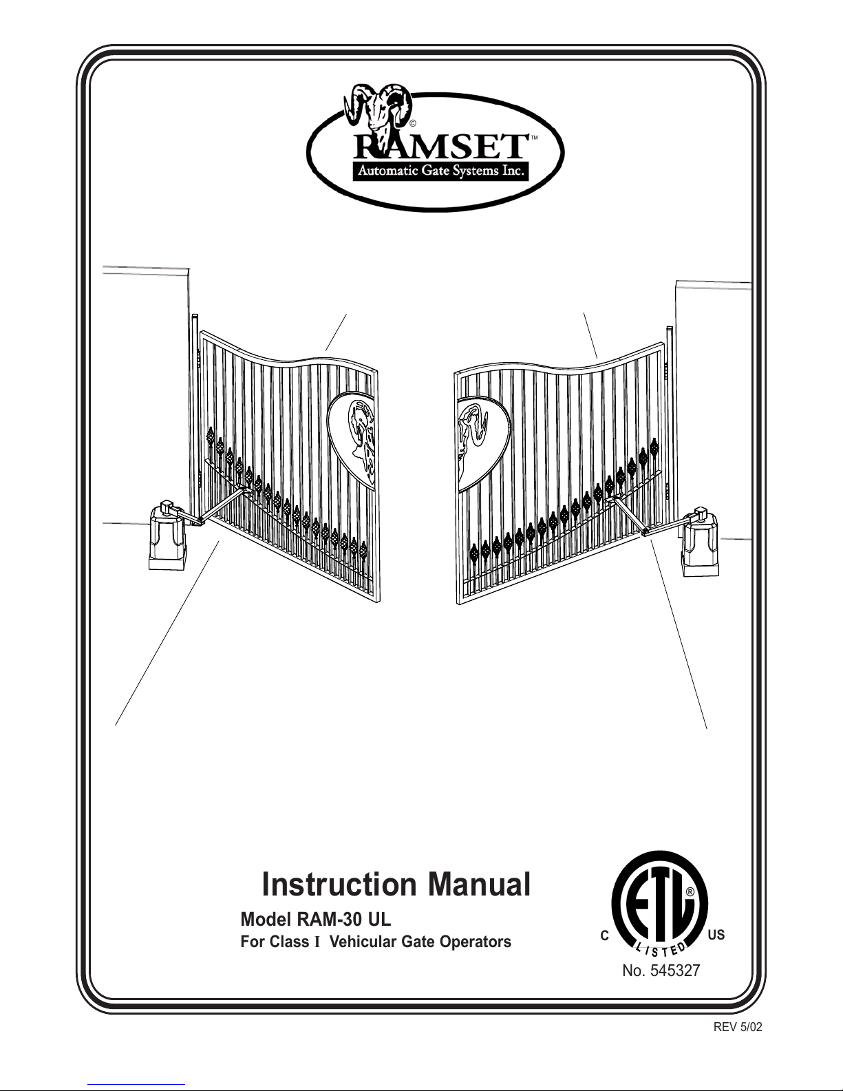
Instruction Manual
Model RAM-30 UL
For Class I Vehicular Gate Operators
No. 545327
US
®
C
©
™
REV 5/02
Page 2

Page 3
T
able of Contents
Important Safety Requirements & Instructions . . . . . . . . . . . . . . . . . . . . . . . . . . . . . . . . . . . . .2,3
Mechanical Specifications . . . . . . . . . . . . . . . . . . . . . . . . . . . . . . . . . . . . . . . . . . . . . . . . . . . .3,4
Installation Specifications
Pad Construction . . . . . . . . . . . . . . . . . . . . . . . . . . . . . . . . . . . . . . . . . . . . . . . . . . . . . . .5
Recommended Wire Gauge / Voltage Drop Chart . . . . . . . . . . . . . . . . . . . . . . . . . . . . . . .5
Installing a Swing Gate Operator . . . . . . . . . . . . . . . . . . . . . . . . . . . . . . . . . . . . . . . . . . .5,6
Gate Travel Adjustment . . . . . . . . . . . . . . . . . . . . . . . . . . . . . . . . . . . . . . . . . . . . . . . . . . . . .7
Pushbutton Controls . . . . . . . . . . . . . . . . . . . . . . . . . . . . . . . . . . . . . . . . . . . . . . . . . . . . . . . .7
Electrical Connection . . . . . . . . . . . . . . . . . . . . . . . . . . . . . . . . . . . . . . . . . . . . . . . . . . . . . . .8
Intelligate PCB Motor Controller Specification
Introduction . . . . . . . . . . . . . . . . . . . . . . . . . . . . . . . . . . . . . . . . . . . . . . . . . . . . . . . . . . .9
DIP Switch Configurations . . . . . . . . . . . . . . . . . . . . . . . . . . . . . . . . . . . . . . . . . . . . . . . .9,10
Terminal Strip Connections . . . . . . . . . . . . . . . . . . . . . . . . . . . . . . . . . . . . . . . . . . . . . . . .10
Control Input Description . . . . . . . . . . . . . . . . . . . . . . . . . . . . . . . . . . . . . . . . . . . . . . .10
Safety Input Description . . . . . . . . . . . . . . . . . . . . . . . . . . . . . . . . . . . . . . . . . . . . . . . .10
Outputs . . . . . . . . . . . . . . . . . . . . . . . . . . . . . . . . . . . . . . . . . . . . . . . . . . . . . . . . . . . .10
Other Connections . . . . . . . . . . . . . . . . . . . . . . . . . . . . . . . . . . . . . . . . . . . . . . . . . . . .10
Wiring Diagram . . . . . . . . . . . . . . . . . . . . . . . . . . . . . . . . . . . . . . . . . . . . . . . . . . . . . . . . . . .11
Sensor Installation . . . . . . . . . . . . . . . . . . . . . . . . . . . . . . . . . . . . . . . . . . . . . . . . . . . . . . . . .12
Master - Slave Installation . . . . . . . . . . . . . . . . . . . . . . . . . . . . . . . . . . . . . . . . . . . . . . . . . . .13
RAM-30 Bill of Materials . . . . . . . . . . . . . . . . . . . . . . . . . . . . . . . . . . . . . . . . . . . . . . . . . . . . .14
RAM-30 Parts Diagram . . . . . . . . . . . . . . . . . . . . . . . . . . . . . . . . . . . . . . . . . . . . . . . . . . . . .15
Glossary . . . . . . . . . . . . . . . . . . . . . . . . . . . . . . . . . . . . . . . . . . . . . . . . . . . . . . . . . . . . . . . . .16
RAMSETzRAMSETzRAMSET
RAMSET
z
RAMSET
z
RAMSET
- 1 -
Page 4
Important Safety Requirements & Instructions
WARNING - To reduce the risk of injury or death:
1. READ AND FOLLOW ALL INSTRUCTIONS!
2. Never let children operate or play with gate controls. Keep the remote control away from children.
3. Always keep people and objects away from the gate. NO ONE SHOULD CROSS THE PATH OF THE
MOVING GATE.
4. Test the Vehicular Gate Operator monthly. The gate MUST reverse on contact with a rigid object or stop
when an object activates the non-contact sensors. After adjusting the limit of travel, retest the Vehicular
Gate Operator. Failure to adjust and retest the Vehicular Gate Operator properly can increase the risk of
injury or death.
5. Use the Emergency Release only when power switch or circuit breaker has been turned off. Using the
Emergency Release during a power failure can be a hazard if power is abruptly restored.
6. KEEP GATES PROPERLY MAINTAINED. Read the Owner's Manual. Have a qualified service person
make repairs to gate hardware.
7. The entrance is for vehicles only. Pedestrians must use separate entrance.
8. SAVE THESE INSTRUCTIONS.
Reversing Sensors (Loop Detectors)
Reversing Sensors should be used to prevent gate from closing when a vehicle is in the gate area.
Ramset Gate Operators should not be installed without non-contact sensing devices such as non-
contact sensors, photo electric sensors or the equivalent.
NOTE: Always consult and follow all local building and electrical codes prior to installation.
Prior to Installation, the following must be observed: (per UL 325 51.8.4)
a) Install the vehicular gate operator only when:
1) The Vehicular Gate Operator is appropriate for the construction of the gate and the usage Class of the gate,
2) All openings of a horizontal slide gate are guarded or screened from the bottom of the gate to a minimum of 4 feet
(1.2 m) above the ground to prevent a 2-1/4 inch (57.15 mm) diameter sphere from passing through the openings
anywhere in the gate, and in that portion of the adjacent fence that the gate covers in the open position.
3) All exposed pinch points are eliminated or guarded, and
4) Guarding is supplied for exposed rollers.
b) The Vehicular Gate Operator is intended for installation only on gates used for vehicles. Pedestrians must be sup-
plied with a separate access opening.
c) The gate must be installed in a location so that enough clearance is supplied between the gate and adjacent struc-
tures when opening and closing to reduce the risk of entrapment. Swinging gates shall not open into public access
areas.
d) The gate must be properly installed and work freely in both directions prior to the installation of the Vehicular Gate
Operator. Do not over-tighten the operator clutch to compensate for a damaged gate.
e) Controls must be far enough from the gate so that the user is prevented from coming in contact with the gate while
n
WARNING
A non-contact sensor (photoelectric sensor or equivalent) and a contact sensor (edge device or equiv-
alent) is required on each individual installation to comply with UL325.
Installation should be done by a qualified installer only.
RAMSETzRAMSETzRAMSET
RAMSET
z
RAMSET
z
RAMSET
- 2 -
Page 5
operating the controls. Controls intended to be used to reset a Vehicular Gate Operator after 2 sequential activations
of the entrapment protection device or devices must be located in the line-of-sight of the gate. Outdoor or easily
accessible controls shall have a security feature to prevent unauthorized use.
f) All warning signs and placards must be installed where visible in the area of the gate.
g) For Vehicular Gate Operators utilizing a non-contact sensor in accordance with 30A.1.1 Type B1 non-contact sensor
(photo electric sensor or the equivalent)
1) See instructions on the placement of non-contact sensors for each Type of application,
2) Care shall be exercised to reduce the risk of nuisance tripping, such as when a vehicle, trips the sensor while
the gate is still moving, and
3) One or more non-contact sensors shall be located where the risk of entrapment or obstruction exists, such as
the perimeter reachable by a moving gate or barrier.
h) For a Vehicular Gate Operator utilizing a contact sensor in accordance with 30A.1.1
1) One or more contact sensors shall be located at the leading edge, trailing edge, and postmounted both inside
and outside of a vehicular horizontal slide gate.
2) One or more contact sensors shall be located at the bottom edge of a vehicular vertical lift gate.
3) One or more contact sensors shall be located at the pinch point of a vehicular vertical pivot gate.
4) A hardwired contact sensor shall be located and its wiring arranged so that the communication between the sen-
sor and the vehicular gate operator is not subjected to mechanical damage.
5) A wireless contact sensor such as one that transmits radio frequency (RF) signals to the vehicular gate operator
for entrapment protection functions shall be located where the transmission of the signals are not obstructed or
impeded by building structures, natural landscaping or similar obstruction. A wireless contact sensor shall func-
tion under the intended end-use conditions.
MECHANICAL SPECIFICATIONS:
Description RAM-30
Power Input: 120 VAC
Electric Motor: 1/2 HP 120VAC, 5.2A, 100 RPM
Capacitor: Aerovox 65µƒ, 240V, 50/60 hz protected S 10000 AFC
Cycles: 30 cycles per hour
ON/OFF Switch: 120VAC
Max. Gate capacity: up to 13 feet
Max. Gate Weight: 400 lbs.
Gate Travel Speed: approx. 14 seconds per 90°
Speed Reducer: by Worm Gear Reducer, continuously lubricated in oil bath.
Chassis: Rust-preventing Gold/Zinc coated 10ga metal
Gate Stops: with Limit Switches
Cover: high-impact resistant Polyethylene
Color: Charcoal Gray
Emergency Release: manual hand release
Shipping Weight: 75 lbs.
Type of Load: Standard - Level
Application: Residential
Overall Dimensions: W=13”, D=12-1/2”, H=20”
RAMSETzRAMSETzRAMSET
RAMSET
z
RAMSET
z
RAMSET
- 3 -
Page 6
RAMSETzRAMSETzRAMSET
RAMSET
z
RAMSET
z
RAMSET
- 4 -
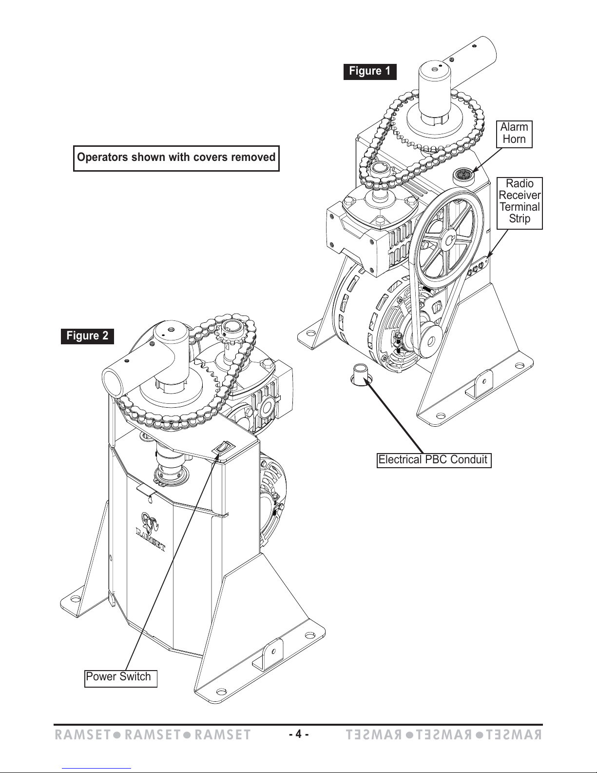
Alarm
Horn
Radio
Receiver
Terminal
Strip
Power Switch
Electrical PBC Conduit
Operators shown with covers removed
Figure 1
Figure 2
Page 7
Installing a Swing Gate Operator
I. Locating the Operator
1. Measure the length of the gate (L).
If the length of the gate is over 12 ft., then
divide the length by 4 (L/4).
If the length of the gate is less than 12 ft, then
divide the length by 3 (L/3).
2. Now clamp the gate bracket near this location.
(Do not weld the bracket until the installation
is completed and thoroughly tested.)
3. When gate is fully closed, mark the point
under the gate bracket where the arm is
going to be attached (L/4 or L/3). (see blue
dot 1, Figure 5)
4. Open gate to desired degree and mark the
point under the gate bracket where the arm is
going to be attached (L/4 or L/3). (see Blue
dot 2, Figure 6)
Inst
allation Specifications
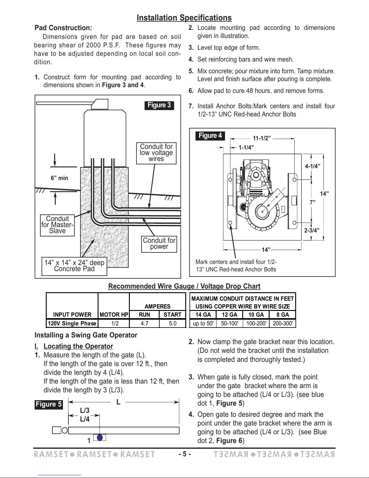
Pad Construction:
Dimensions given for pad are based on soil
bearing shear of 2000 P.S.F. These figures may
have to be adjusted depending on local soil con-
dition.
1. Construct form for mounting pad according to
dimensions shown in Figure 3 and 4.
2. Locate mounting pad according to dimensions
given in illustration.
3. Level top edge of form.
4. Set reinforcing bars and wire mesh.
5. Mix concrete; pour mixture into form. Tamp mixture.
Level and finish surface after pouring is complete.
6. Allow pad to cure 48 hours, and remove forms.
7. Install Anchor Bolts:Mark centers and install four
1/2-13” UNC Red-head Anchor Bolts
L
L/3
L/4
Figure 5
1
Figure 3
Conduit for
low voltage
wires
14” x 14” x 24” deep
Concrete Pad
Conduit for
power
Conduit
for Master-
Slave
6” min
14”
7”
2-3/4”
11-1/2”
1-1/4”
4-1/4”
14”
Mark centers and install four 1/2-
13” UNC Red-head Anchor Bolts
Figure 4
RUN START 14 GA 12 GA 10 GA 8 GA
120V Single Phase 1/2 4.7 5.0 up to 50' 50-100' 100-200' 200-300'
AMPERES
MAXIMUM CONDUIT DISTANCE IN FEET
USING COPPER WIRE BY WIRE SIZE
INPUT POWER
MOTOR HP
Recommended Wire Gauge / Voltage Drop Chart
RAMSETzRAMSETzRAMSET
RAMSET
z
RAMSET
z
RAMSET
- 5 -
Page 8
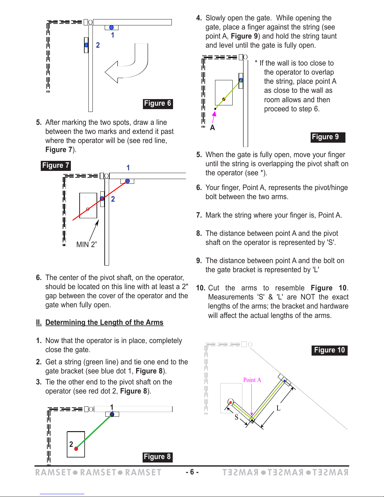
5. After marking the two spots, draw a line
between the two marks and extend it past
where the operator will be (see red line,
Figure 7).
6. The center of the pivot shaft, on the operator,
should be located on this line with at least a 2"
gap between the cover of the operator and the
gate when fully open.
II.
Determining the Length of the Arms
1. Now that the operator is in place, completely
close the gate.
2. Get a string (green line) and tie one end to the
gate bracket (see blue dot 1, Figure 8).
3. Tie the other end to the pivot shaft on the
operator (see red dot 2, Figure 8).
4. Slowly open the gate. While opening the
gate, place a finger against the string (see
point A, Figure 9) and hold the string taunt
and level until the gate is fully open.
5. When the gate is fully open, move your finger
until the string is overlapping the pivot shaft on
the operator (see *).
6. Your finger, Point A, represents the pivot/hinge
bolt between the two arms.
7. Mark the string where your finger is, Point A.
8. The distance between point A and the pivot
shaft on the operator is represented by 'S'.
9. The distance between point A and the bolt on
the gate bracket is represented by 'L'
10. Cut the arms to resemble Figure 10.
Measurements 'S' & 'L' are NOT the exact
lengths of the arms; the bracket and hardware
will affect the actual lengths of the arms.
1
2
Min.
Figure 7
2
1
MIN 2”
1
2
Figure 8
2
1
2
Figure 6
A
.
Figure 9
.
.
S
L
.
Point A
Figure 10
* If the wall is too close to
the operator to overlap
the string, place point A
as close to the wall as
room allows and then
proceed to step 6.
A
1
2
RAMSETzRAMSETzRAMSET
RAMSET
z
RAMSET
z
RAMSET
- 6 -
Page 9
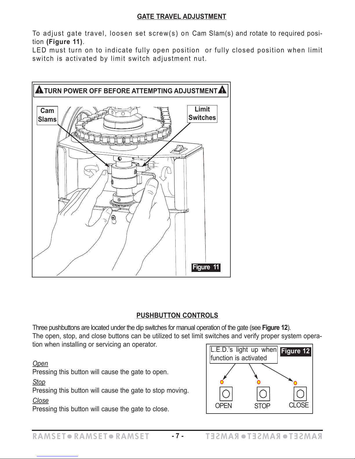
Three pushbuttons are located under the dip switches for manual operation of the gate (see Figure 12).
The open, stop, and close buttons can be utilized to set limit switches and verify proper system opera-
tion when installing or servicing an operator.
Open
Pressing this button will cause the gate to open.
S
top
Pressing this button will cause the gate to stop moving.
Close
Pressing this button will cause the gate to close.
GATE TRAVEL ADJUSTMENT
To adjust gate travel, loosen set screw(s) on Cam Slam(s) and rotate to required posi-
tion (Figure 11).
LED must turn on to indicate fully open position or fully closed position when limit
switch is activated by limit switch adjustment nut.
PUSHBUTTON CONTROLS
OPEN
STOP
CLOSE
L.E.D.’s light up when
function is activated
Figure 12
Cam
Slams
Limit
Switches
Figure 11
n
TURN POWER OFF BEFORE ATTEMPTING ADJUSTMENT
n
RAMSETzRAMSETzRAMSET
RAMSET
z
RAMSET
z
RAMSET
- 7 -
Page 10
RAMSETzRAMSETzRAMSET
RAMSET
z
RAMSET
z
RAMSET
- 8 -
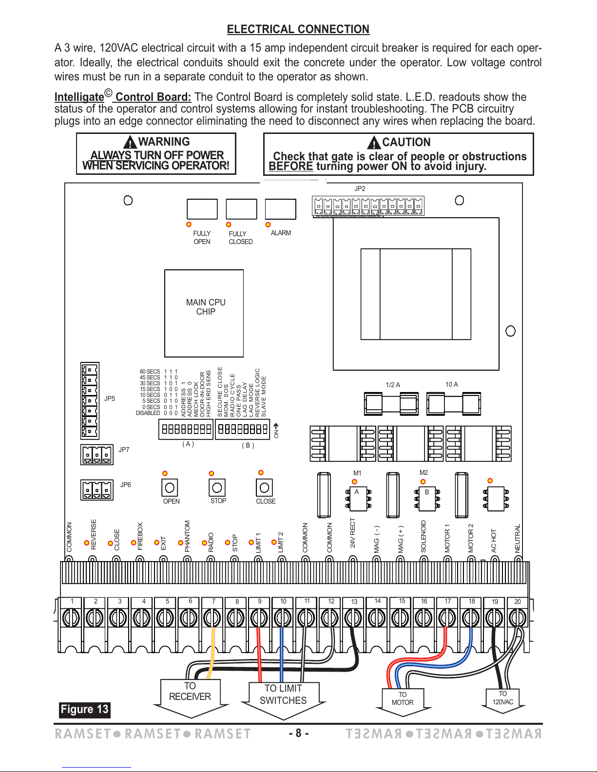
ELECTRICAL
CONNECTION
A 3 wire, 120VAC electrical circuit with a 15 amp independent circuit breaker is required for each oper-
ator. Ideally, the electrical conduits should exit the concrete under the operator. Low voltage control
wires must be run in a separate conduit to the operator as shown.
Intelligate© Control Board: The Control Board is completely solid state. L.E.D. readouts show the
status of the operator and control systems allowing for instant troubleshooting. The PCB circuitry
plugs into an edge connector eliminating the need to disconnect any wires when replacing the board.
n
WARNING
AL
WAYS TURN OFF POWER
WHEN SERVICING OPERATOR!
n
CAUTION
Check that gate is clear of people or obstructions
BEFORE
turning power ON to avoid injury.
MAIN CPU
CHIP
OPEN
FULLY
OPEN
FULLY
CLOSED
ALARM
JP6
1/2 A
10 A
JP5
JP7
JP2
1 2 3 4 5
6
7
8
9
10
11
12
13
14
15
16 17 18
19
20
STOP
CLOSE
A
M1
M2
B
COMMON
REVERSE
FIREBOX
EXIT
PHANTOM
ADDRESS 1
ADDRESS 0
MECH LOCK
DOOR-IN-DOOR
HIGH ERD SENS
SECURE CLOSE
MOM. SOS
RADIO CYCLE
ONE PASS
LAG DELAY
LAG MODE
REVERSE LOGIC
SLAVE MODE
ONÎ
60 SECS 1 1 1
45 SECS 1 1 0
30 SECS 1 0 1
15 SECS 1 0 0
10 SECS 0 1 1
5 SECS 0 1 0
0 SECS 0 0 1
DISABLED 0 0 0
RADIO
STOP
LIMIT 1
LIMIT 2
COMMON
COMMON
24V RECT
MAG ( - )
MOTOR 1
MOTOR 2
AC HOT
NEUTRAL
MAG ( + )
SOLENOID
CLOSE
TO
120VAC
Figure 13
( A )
( B )
TO LIMIT
SWITCHES
TO
RECEIVER
TO
MOTOR
Page 11
INTRODUCTION
Ramset’s “Intelligate” Control board is for operating a vehicular
gate operator. The control board is available for either 110VAC or
220VAC, single phase, applications. The control board contains
self adjusting ERD, left hand/right hand operation control,
lead/lag capability, one-pass anti-tailgating, and options for 4 dif-
ferent gate addresses. The control board also includes a rectified
24V, 750mA, output for providing power to peripheral devices
such as radio receivers, keypads, alarms, phone entry systems,
safety detectors…etc.
DIP SWITCH CONFIGURA
TION
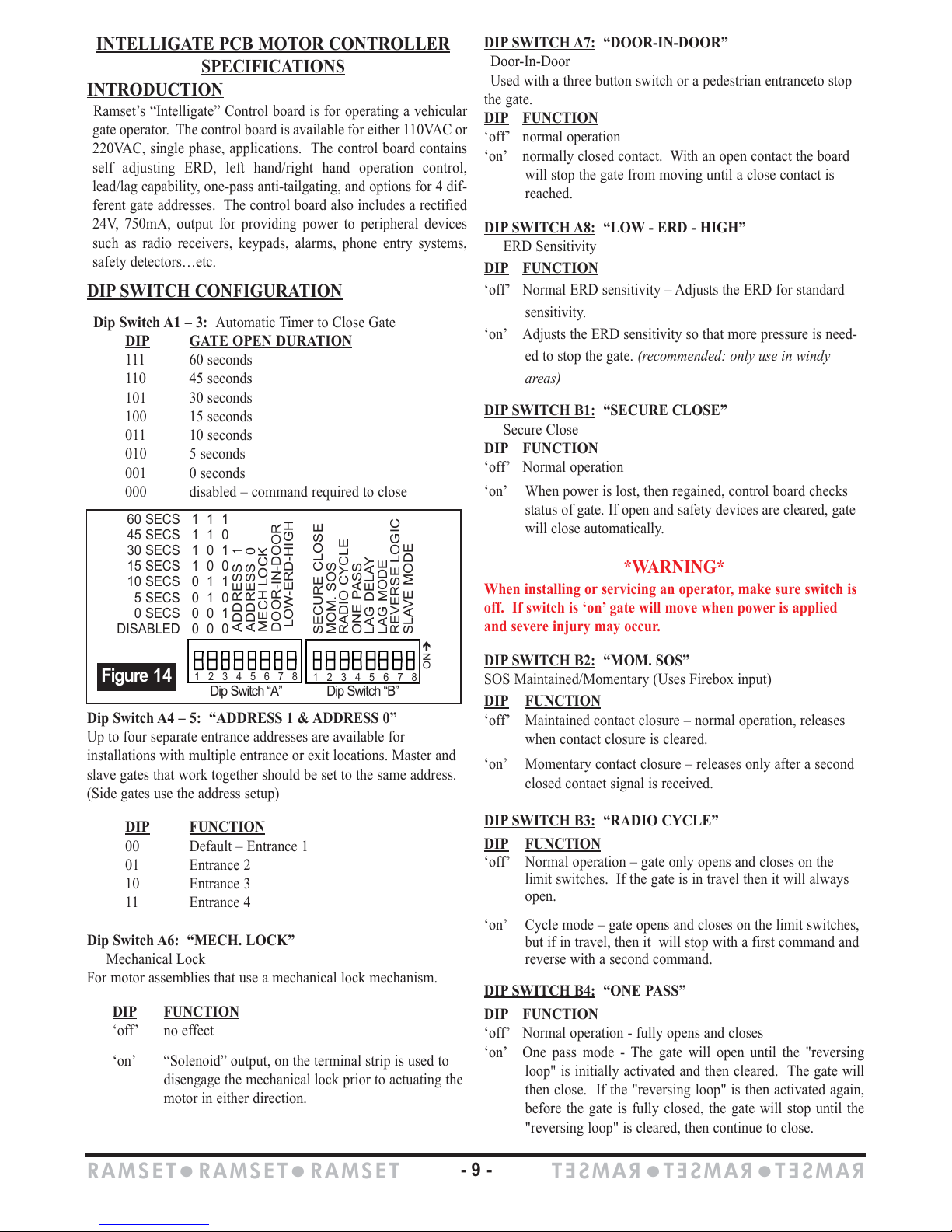
Dip Switch A1 – 3: Automatic Timer to Close Gate
DIP GATE OPEN DURATION
111 60 seconds
110 45 seconds
101 30 seconds
100 15 seconds
011 10 seconds
010 5 seconds
001 0 seconds
000 disabled – command required to close
Dip Switch A4 – 5: “ADDRESS 1 & ADDRESS 0”
Up to four separate entrance addresses are available for
installations with multiple entrance or exit locations. Master and
slave gates that work together should be set to the same address.
(Side gates use the address setup)
DIP
FUNCTION
00 Default – Entrance 1
01 Entrance 2
10 Entrance 3
11 Entrance 4
Dip Switch A6: “MECH. LOCK”
Mechanical Lock
For motor assemblies that use a mechanical lock mechanism.
DIP
FUNCTION
‘off’ no effect
‘on’ “Solenoid” output, on the terminal strip is used to
disengage the mechanical lock prior to actuating the
motor in either direction.
DIP
SWITCH A7: “DOOR-IN-DOOR”
Door-In-Door
Used with a three button switch or a pedestrian entranceto stop
the gate.
DIP
FUNCTION
‘off’ normal operation
‘on’ normally closed contact. With an open contact the board
will stop the gate from moving until a close contact is
reached.
DIP
SWITCH A8: “LOW - ERD - HIGH”
ERD Sensitivity
DIP FUNCTION
‘off’ Normal ERD sensitivity – Adjusts the ERD for standard
sensitivity.
‘on’ Adjusts the ERD sensitivity so that more pressure is need-
ed to stop the gate. (recommended: only use in windy
areas)
DIP SWITCH B1: “SECURE CLOSE”
Secure Close
DIP FUNCTION
‘off’ Normal operation
‘on’ When power is lost, then regained, control board checks
status of gate. If open and safety devices are cleared, gate
will close automatically.
*WARNING*
When installing or servicing an operator, make sure switch is
off. If switch is ‘on’ gate will move when power is applied
and severe injury may occur.
DIP
SWITCH B2: “MOM. SOS”
SOS Maintained/Momentary (Uses Firebox input)
DIP
FUNCTION
‘off’ Maintained contact closure – normal operation, releases
when contact closure is cleared.
‘on’ Momentary contact closure – releases only after a second
closed contact signal is received.
DIP
SWITCH B3: “RADIO CYCLE”
DIP FUNCTION
‘off’ Normal operation – gate only opens and closes on the
limit switches. If the gate is in travel then it will always
open.
‘on’ Cycle mode – gate opens and closes on the limit switches,
but if in travel, then it will stop with a first command and
reverse with a second command.
DIP
SWITCH B4: “ONE PASS”
DIP
FUNCTION
‘off’ Normal operation - fully opens and closes
‘on’ One pass mode - The gate will open until the "reversing
loop" is initially activated and then cleared. The gate will
then close. If the "reversing loop" is then activated again,
before the gate is fully closed, the gate will stop until the
"reversing loop" is cleared, then continue to close.
INTELLIGATE PCB MOTOR CONTROLLER
SPECIFICATIONS
ADDRESS 1
ADDRESS 0
MECH LOCK
DOOR-IN-DOOR
LOW-ERD-HIGH
SECURE CLOSE
MOM. SOS
RADIO CYCLE
ONE PASS
LAG DELAY
LAG MODE
REVERSE LOGIC
SLAVE MODE
ONÎ
1 2 3 4 5 6 7 8
Dip Switch “A”
Dip Switch “B”
60 SECS 1 1 1
45 SECS 1 1 0
30 SECS 1 0 1
15 SECS 1 0 0
10 SECS 0 1 1
5 SECS 0 1 0
0 SECS 0 0 1
DISABLED 0 0 0
Figure 14
1 2 3 4 5 6 7 8
RAMSETzRAMSETzRAMSET
RAMSET
z
RAMSET
z
RAMSET
- 9 -
Page 12
DIP SWITCH B5: “LAG DELAY”
Lag on Close
One second lag on close
DIP
SWITCH B6: “LAG MODE”
Lag on Open
One second lag on open
DIP
SWITCH B7: “REVERSE LOGIC”
DIP
FUNCTION
‘off’ Left hand operation – standard installation
‘on’ Right hand installations – Reverses motor & limit switches
without having to move any wires.
DIP
SWITCH B8:
“SLAVE MODE”
Master/slave
DIP
FUNCTION
‘off’ Master mode – single gate operation. All peripheral
devices are to be connected to the master operator.
‘on’ Slave mode – used to synchronize operation between two
gates. Commands are received from the master through a
3-wire, shielded cable.
TERMINAL STRIP CONNECTIONS
CONTROL INPUT DESCRIPTIONS
AC Hot & Neutral – 110 or 220 VAC to power the operator.
Voltage is predetermined at factory and cannot be changed
by the installer or technician.
Close – Closes the gate. Used with three button stations
or pushbuttons. Becomes active with a closed contact to
common.
Exit – Opens the gate. Used with loop detectors, photo
eyes, keypads, phone entry systems, three-button sta-
tions…etc. Becomes active with a closed contact to com-
mon.
Firebox/SOS – Opens the gate. Used with fire dept. key
switches & controls. Becomes active with a closed contact
to common, maintained or momentary depending on dip
switch B2 (see “dip switch features”).
Stop – Stops the operator from moving. To be used as a
non-contact sensor such as a photo-beam, edge connector
or a three-button station. Becomes active with an open con-
tact to common when dip switch A7 is in the ‘on’ position
(see “dip switch features”).
Radio – Operation depends on dip switch B3 (see “dip
switch features”). Used with an RF receiver or pushbutton.
Becomes active with a closed contact to common.
SAFETY INPUT DESCRIPTION
Limit 1 & Limit 2 – Depending on dip switch B7 (see “dip
switch features”), stops the motor from moving in one direc-
tion. These wires are preset in factory and should not be
moved. Becomes active with a closed contact to common.
Phantom – Keeps the gate open when the open limit switch
(A or B) is activated. Used with loop detectors. Becomes
active with a closed contact to common.
Rev Loop – Stops the gate from closing. If the gate is open,
it holds the gate open. If the gate is closing, it stops and
reopens the gate. If the gate is closed, the gate will remain
closed. The function can be altered with dip switch B4 (see
“dip switch features”). Used with loop detectors, photo eyes,
safety edges…etc. Becomes active with a closed contact to
common.
OUTPUTS
Mag (+) & Mag (- )
Supplies 24VDC to a magnetic lock when gate is closed. If
gate is not closed then no power is supplied. Leave open if not
used.
Motor 1 & Motor 2 – Supplies power to the motor. Direction
depends on dip switch B7 (see “dip switch features”). These
wires are preset and connected in the factory and should not
be moved.
24V Rect. – Provides a rectified 24VDC for peripheral acces-
sories.
Solenoid – Sends 110 VAC to a solenoid or other mechani-
cal lock. Leave open if not used.
OTHER CONNECTIONS
Contact Closure Relay Outputs
Three separate isolated form-C relay outputs are provided.
Each relays contact is rated at 125VAC, 2 amps.
1. Alarm – When ERD is triggered twice, before reaching a
fully closed or fully opened position, 24VDC is supplied
for 6 minutes and the control board will not accept any
commands. After the 6 minutes the 24VDC is removed
and the board resets to normal operation.
2. Triggers relay when gate is fully opened. Used with indi-
cator lights, buzzers, beepers, misc. voltage magnetic
locks…etc.
3. Triggers relay when gate is fully closed. Used with indi-
cator lights, buzzers, beepers, misc. voltage magnetic
locks…etc.
Note: if both B5 &
B6 are 'on', there
will be NO lag on
the open or close.
RAMSETzRAMSETzRAMSET
RAMSET
z
RAMSET
z
RAMSET
- 10 -
Page 13
1 2 3 4 5
6
7
8
9
10
11
12
13
19
20
14
15
16 17 18
COMMON
REVERSE LOOP
FIREBOX
STOP
PHANTOM
RADIO
EXIT
LIMIT 1
LIMIT 2
COMMON
COMMON
24V RECT
MAG ( - )
MOTOR 2
MOTOR 1
AC HOT
NEUTRAL
MAG ( + )
SOLENOID
CLOSE
Figure 15
Capacitor
Radio
Terminal Strip
Mag
Lock
Solenoid
BL
BK
BK
RD
WH
WH
WH
WH
WH
YL
GR
RD
RD
RD
BK
BK
BK
Motor
BL
BL
TO
120VAC
POWER
SWITCH
120V
120V ACAC
or 220V
or 220V ACAC
N.C.
N.O.
N.O.
Limit Switch
Limit Switch
C
C
N.C.
Firebox
Pedestrian
Switch
Phantom
Loop
Exit Loop
Open
3 button station
Common
Stop
Close
Reversing Loop
Electronic Control Board must be serviced by a certified technician only.
Power must be turned OFF before servicing operator.
Power must be turned OFF before attempting to adjust the limit switches.
Power must be turned OFF
for power failure release.
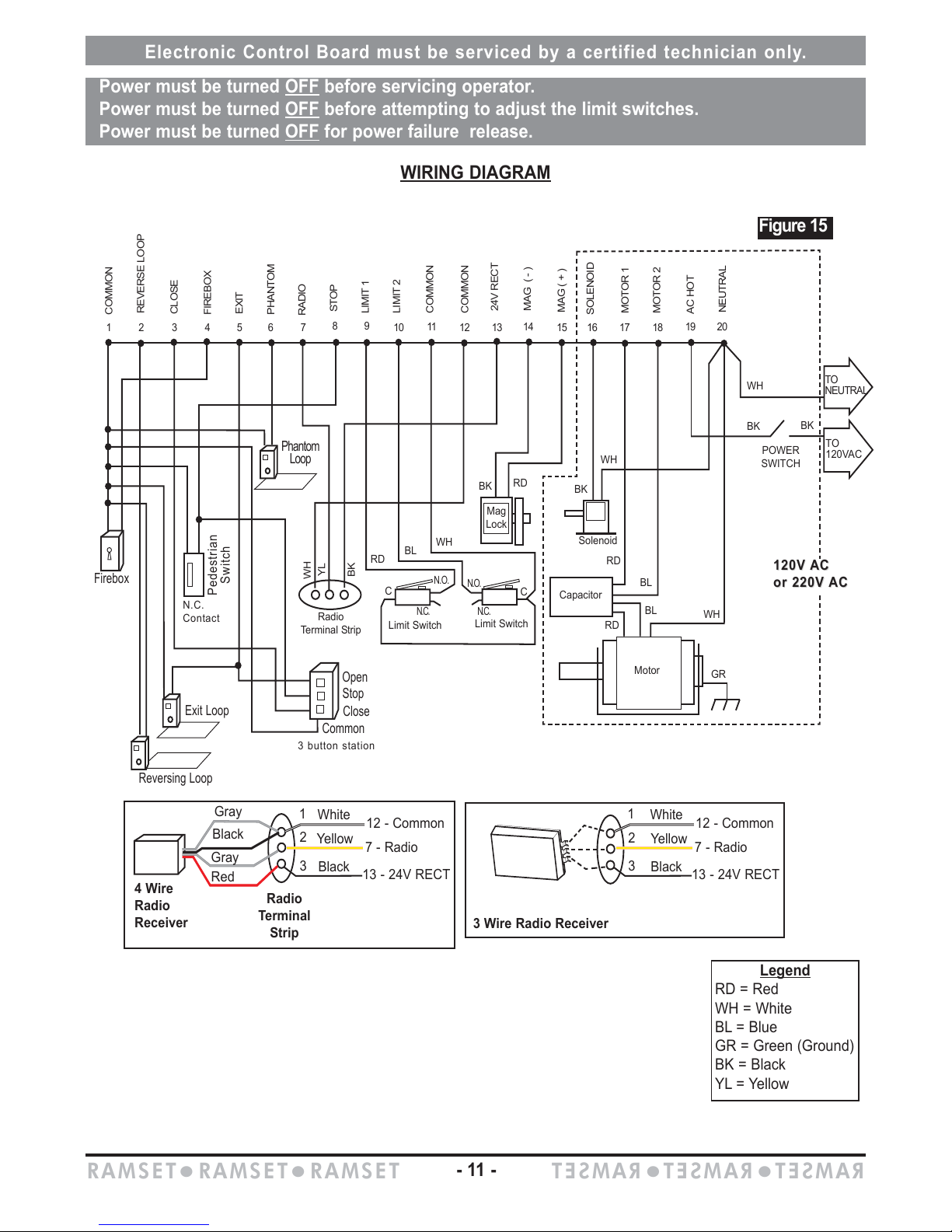
WIRING DIAGRAM
TO
NEUTRAL
Legend
RD = Red
WH = White
BL = Blue
GR = Green (Ground)
BK = Black
YL = Yellow
12 - Common
7 - Radio
13 - 24V RECT
3 Wire Radio Receiver
4 Wire
Radio
Receiver
Radio
Terminal
Strip
Gray
White
Yellow
Black
1
2
3
1
2
3
Black
Red
Gray
12 - Common
7 - Radio
13 - 24V RECT
White
Yellow
Black
RAMSETzRAMSETzRAMSET
RAMSET
z
RAMSET
z
RAMSET
- 11 -
N.C.
Contact
Page 14
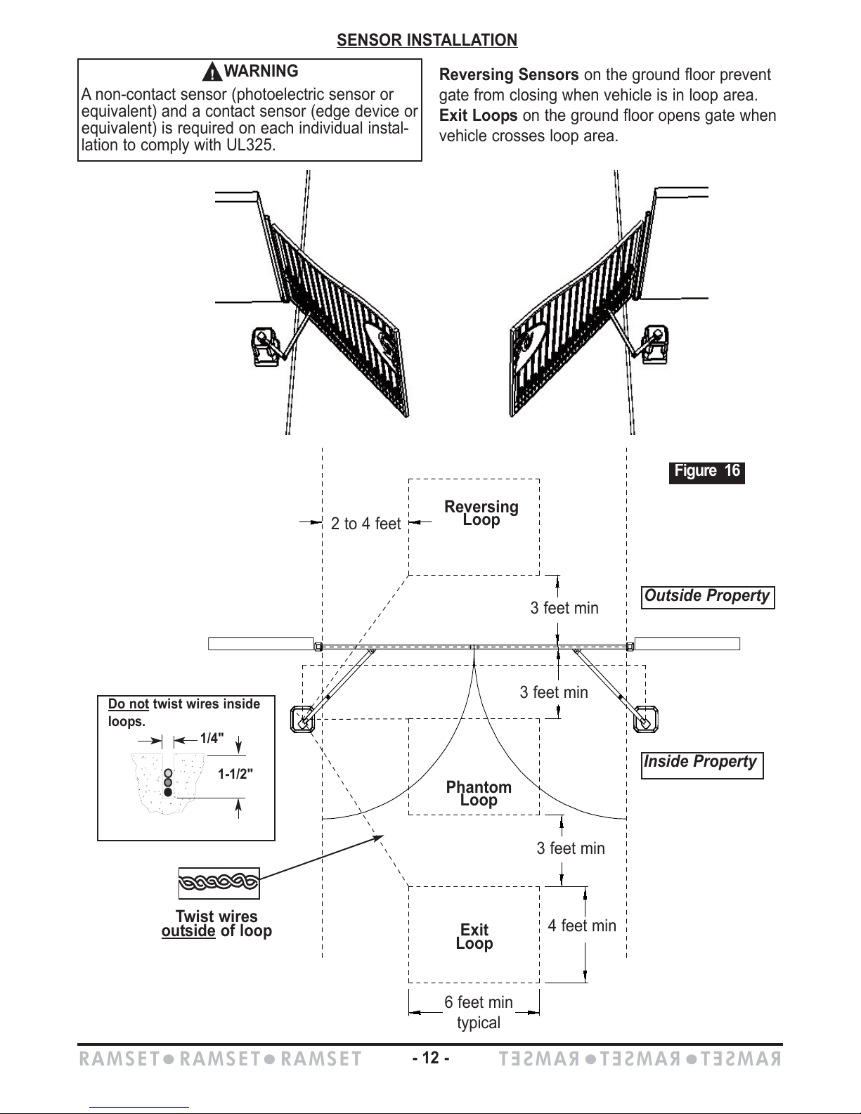
SENSOR INSTALLATION
n
WARNING
A non-contact sensor (photoelectric sensor or
equivalent) and a contact sensor (edge device or
equivalent) is required on each individual instal-
lation to comply with UL325.
Twist wires
out
side of loop
Inside Property
Outside Property
Figure 16
Phantom
Loop
Exit
Loop
3 feet min
3 feet min
2 to 4 feet
3 feet min
4 feet min
6 feet min
typical
Do not twist wires inside
loops.
1/4"
1-1/2"
Reversing Sensors on the ground floor prevent
gate from closing when vehicle is in loop area.
Exit Loops on the ground floor opens gate when
vehicle crosses loop area.
Reversing
Loop
RAMSETzRAMSETzRAMSET
RAMSET
z
RAMSET
z
RAMSET
- 12 -
Page 15
Use jumper
JP6 to JP6
JP6
Use jumper
JP6 to JP6
JP6
MASTER-SLA
VE INSTALLATION
Figure 17
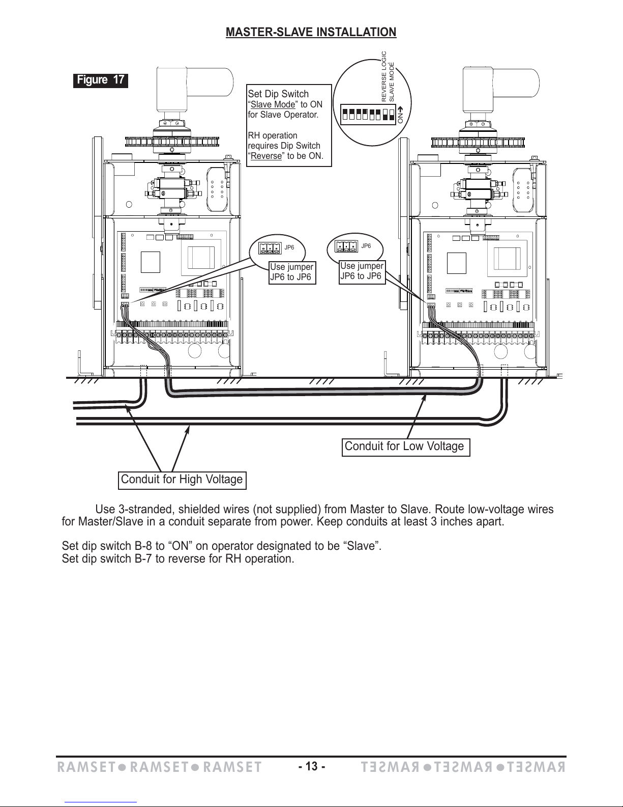
Use 3-stranded, shielded wires (not supplied) from Master to Slave. Route low-voltage wires
for Master/Slave in a conduit separate from power. Keep conduits at least 3 inches apart.
Set dip switch B-8 to “ON” on operator designated to be “Slave”.
Set dip switch B-7 to reverse for RH operation.
SLAVE MODE
REVERSE LOGIC
ONÎ
Set Dip Switch
“Slave Mode” to ON
for Slave Operator.
RH operation
requires Dip Switch
“Reverse
” to be ON.
RAMSETzRAMSETzRAMSET
RAMSET
z
RAMSET
z
RAMSET
- 13 -
Conduit for Low Voltage
Conduit for High Voltage
Page 16
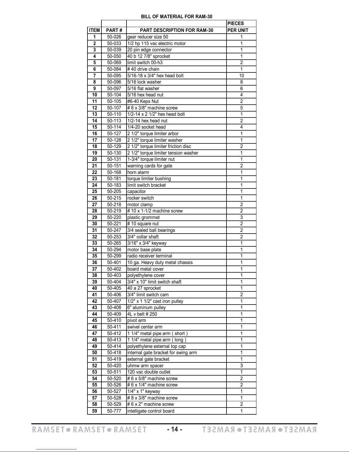
BILL OF MATERIAL FOR RAM-30
PIECES
ITEM PART # PART DESCRIPTION FOR RAM-30 PER UNIT
1 50-026 gear reducer size 50 1
2 50-033 1/2 hp 115 vac electric motor 1
3 50-039 20 pin edge connector 1
4 50-050 40 b 12 7/8" sprocket 1
5 50-069 limit switch 00-h3 2
6 50-084 # 40 drive chain 1
7 50-095 5/16-18 x 3/4" hex head bolt 10
8 50-096 5/16 lock washer 8
9 50-097 5/16 flat washer 6
10 50-104 5/16 hex head nut 4
11 50-105 #6-40 Keps Nut 2
12 50-107 # 6 x 3/8" machine screw 5
13 50-110 1/2-14 x 2 1/2" hex head bolt 1
14 50-113 1/2-14 hex head nut 2
15 50-114 1/4-20 socket head 4
16 50-127 2 1/2" torque limiter arbor 1
17 50-128 2 1/2" torque limiter washer 1
18 50-129 2 1/2" torque limiter friction disc 2
19 50-130 2 1/2" torque limiter tension washer 1
20 50-131 1-3/4" torque limiter nut 1
21 50-151 warning cards for gate 2
22 50-168 horn alarm 1
23 50-181 torque limiter bushing 1
24 50-183 limit switch bracket 1
25 50-205 capacitor 1
26 50-215 rocker switch 1
27 50-218 motor clamp 2
28 50-219 # 10 x 1-1/2 machine screw 2
29 50-220 plastic grommet 3
30 50-221 # 10 square nut 2
31 50-247 3/4 sealed ball bearings 2
32 50-253 3/4" collar shaft 2
33 50-265 3/16" x 3/4" keyway 1
34 50-294 motor base plate 1
35 50-299 radio receiver terminal 1
36 50-401 10 ga. Heavy duty metal chassis 1
37 50-402 board metal cover 1
38 50-403 polyethylene cover 1
39 50-404 3/4" x 10" limit switch shaft 1
40 50-405 40 a 27 sprocket 1
41 50-406 3/4" limit switch cam 2
42 50-407 1/2" x 1 1/2" cast iron pulley 1
43 50-408 6" aluminum pulley 1
44 50-409 4L v belt # 250 1
45 50-410 pivot arm 1
46 50-411 swivel center arm 1
47 50-412 1 1/4" metal pipe arm ( short ) 1
48 50-413 1 1/4" metal pipe arm ( long ) 1
49 50-414 polyethylene external top cap 1
50 50-418 internal gate bracket for swing arm 1
51 50-419 external gate bracket 1
52 50-420 uhmw arm spacer 3
53 50-511 120 vac double outlet 1
54 50-520 # 6 x 5/8" machine screw 2
55 50-526 # 6 x 1/4" machine screw 2
56 50-527 1/4" x 1" keyway 1
57 50-528 # 8 x 3/8" machine screw 1
58 50-529 # 6 x 2" machine screw 2
59 50-777 intelligate control board 1
RAMSETzRAMSETzRAMSET
RAMSET
z
RAMSET
z
RAMSET
- 14 -
Page 17
13
16
18
19
18
43
54
57
20
17
3
12
59
58
40
15
46
52
47
52
38
50
14
51
39
5
12
6
21
52
49
56
33
37
55
24
11
12
48
23
9
8
28
30
27
2
34
25
10
4
44
26
1
35
45
41
32
42
31
36
53
29
7
22
14
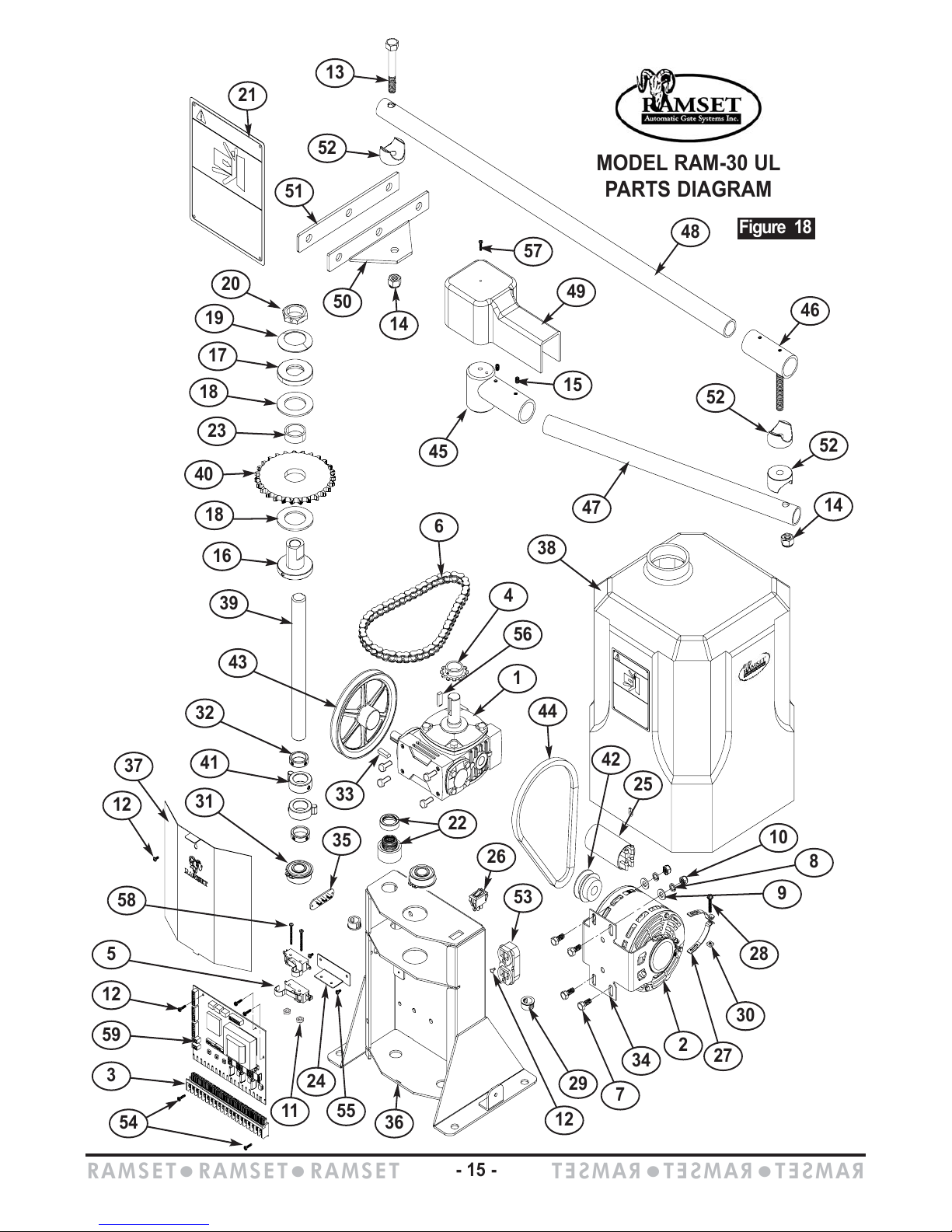
MODEL RAM-30 UL
PARTS DIAGRAM
Figure 18
RAMSETzRAMSETzRAMSET
RAMSET
z
RAMSET
z
RAMSET
- 15 -
Page 18
GLOSSARY
CLASSES OF VEHICULAR GA
TE OPERATORS
VEHICULAR HORIZONTAL SLIDE-GATE OPERATOR (OR SYSTEM)- A vehicular gate operator
(or system) that controls a gate which slides in a horizontal direction that is intended for use for
vehicular entrance or exit to a drive, parking lot, or the like.
VEHICULAR SWING-GATE OPERATOR (OR SYSTEM) - A vehicular gate operator (or system) that
controls a gate which swings in an arc in a horizontal plane that is intended for use for vehicular
entrance or exit to a drive, parking lot or the like.
RESIDENTIAL VEHICULAR GATE OPERATOR-CLASS I - A vehicular gate operator (or system)
intended for use in a home of one-to four single family dwellings, or a garage or parking area associ-
ated therewith.
COMMERCIAL/GENERAL ACCESS VEHICULAR GATE OPERATOR- CLASS II- A vehicular gate
operator (or system) intended for use in an commercial location or building such as a multi-family
housing unit (five or more single family units), hotels, garages, retail stores, or other buildings serv-
ing the general public.
INDUSTRIAL/LIMITED ACCESS VEHICULAR GATE OPERATOR - CLASS III - A vehicular gate
operator (or system) intended for use in an industrial location or building such as a factory or loading
dock area or other locations not intended to service the general public.
RESTRICTED ACCESS VEHICULAR GATE OPERATOR - CLASS IV - A vehicular gate operator
(or system) intended for use in a guarded industrial location or building such as an airport security
area or other restricted access locations not servicing the general public, in which unauthorized
access is prevented via supervision by security personnel.
VISIT
VISIT
OUR WEBSITE
OUR WEBSITE AATT
: WWW
: WWW
.RAMSETINC.COM
.RAMSETINC.COM
Ramset Automatic Gate Systems z (800) 771-7055 z 9116
De Garmo Ave. z Sun Valley, CA. 91352
 Loading...