

Page 1
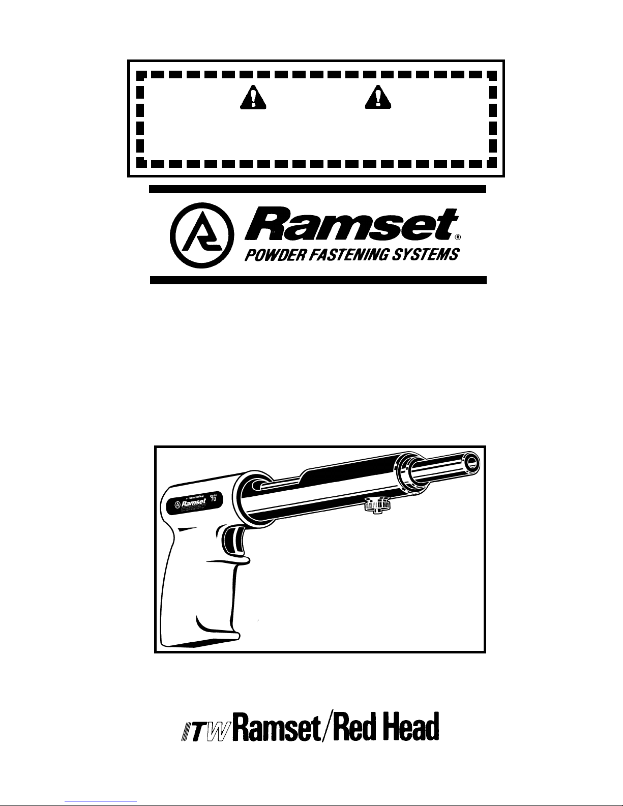
THIS TOOL FOR USE BY LICENSED OPERATORS ONLY.
READ AND OBEY ALL SAFETY AND OPERATING
INSTRUCTIONS BEFORE OPERATING TOOL.
M70 TOOL
OPERATOR’S
SAFETY &
OPERATING
INSTRUCTION
MANUAL
SINGLE SHOT, LOW VELOCITY
PISTON TYPE FASTENING TOOL
DANGER
Page 2
DANGER
SAFETY INTRODUCTION
DANGER
SAFETY INTRODUCTION
2
DANGER
THIS TOOL IS TO BE USED ONLY BY PROPERLY TRAINED
AND LICENSED OPERATORS.
YOU MUST SUCCESSFULLY COMPLETE ITW RAMSET/RED HEAD’S
TRAINING PROGRAM FOR THE TOOL AND OBTAIN
A CERTIFIED OPERATOR’S LICENSE BEFORE HANDLING,
LOADING OR OPERATING THIS TOOL.
ATTEMPTING TO HANDLE OR OPERATE THIS TOOL
WITHOUT PROPER TRAINING AND LICENSING CAN RESULT IN
SERIOUS INJURY TO THE OPERATOR OR BYSTANDERS.
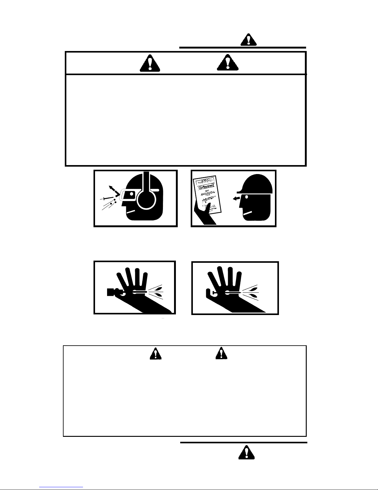
Operator’s and bystanders
must wear eye and hear-
ing protection.
Read manual before
operating tool.
Never close tool with hand over fastener loading end of the tool.
A serious hand injury from penetration by the piston or a
discharged fastener could result.
DANGER
Just as no one can merely read a book about driving an automobile and then hope
to drive one safely, no one should attempt to use any Ramset tool without adequate,
competent personal instruction. And just as one must be licensed to drive an
automobile, one must also be licensed to use a powder actuated tool.
No automobile instruction book or instructor can forewarn a learner against all possibilities and emergencies, nor can ITW Ramset/Red Head instructors and printed
material detail all possible conditions surrounding the use of ITW Ramset/Red Head
tools and products.
Responsibility for the safe and proper use of this tool rests with the tool
user and the employer.
Page 3
SAFETY INSTRUCTIONS
DANGER
DANGER
SAFETY INSTRUCTIONS
3
Preparation
Acceptable Base Materials
Powder actuated fastening is suitable for use in the following base
materials only:
• Poured Concrete
• Structural Steel
• Masonry Joints ( see page 8)
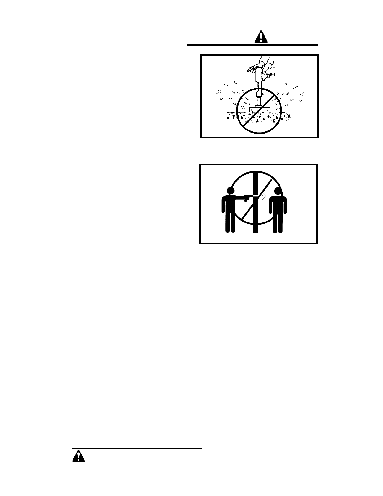
Never attempt to fasten into any
other type of material. Fastening into
other materials can cause blindness or
other serious injury.
Unacceptable Base Materials
Never attempt to fasten into very
hard or brittle materials such as cast
iron, tile, glass, or rock of any type.
These materials can shatter, causing
the fastener and/or base material
fragments to fly free and cause
serious injury to the tool operator
and others.
Never fasten into soft base
materials, such as drywall or lumber
products. These materials may allow
the fastener to travel completely through
and out the other side, endangering
those in the path of the fastener.
Never fasten into any base material
that does not pass the Center Punch
test. Failure to assure the suitability of
the base material can result in serious
injury to the eyes or other body parts.
NEVER FASTEN INTO VERY
HARD OR BRITTLE MATERIALS
NEVER FASTEN INTO SOFT
MATERIALS SUCH AS DRYWALL
Center Punch Test
ALWAYS WEAR SAFETY GOGGLES
WHEN PERFORMING THIS TEST.
1. Always check the material
being fastened into for hardness before attempting any
fastening operation.
2. Using a fastener as a center
punch, strike the fastener
against the work surface using
an average hammer blow and
check the results.
Center Punch Test Results
1. If the fastener point is flattened,
the material is too hard for a
powder actuated fastening.
2. If the fastener penetrates the
material easily, the material is
too soft.
3. If the material cracks or
shatters, the material is too
brittle.
4. If the fastener makes a small
indentation into the material,
the material is suitable for
fastening.
Page 4
SAFETY INSTRUCTIONS
DANGER
DANGER
SAFETY INSTRUCTIONS
4
Loads & Load Selection Safety
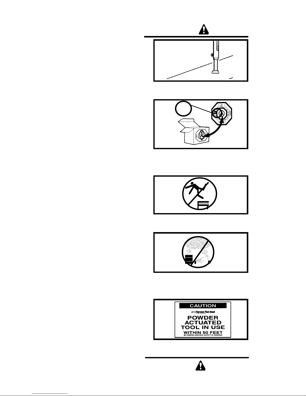
1. Always make a test fastening
after being sure that the base
material is suitable for powder
actuated fastening. Failure to
determine the correct power level
to be used may result in the use
of excessive power, allowing the
fastener to pass completely
through the work material,
causing serious or fatal injuries to
others who may be in the path of
the fastener.
2. Color-blind operators must always select loads by load number
to prevent use of an incorrect
load for the same reasons as in #1
above.
Workplace Safety
1. Operators and bystanders must
always wear approved safety
goggles and approved hearing
protection. Failure to do so may
result in blindness or serious eye
injury from flying debris and loss
of hearing from constant or
repeated unprotected exposure to
fastening noise.
2. Always keep the work area clear
of bystanders and unnecessary
materials that could interfere with
safe tool operation. Operating the
tool in a congested or cluttered
area may affect your ability to
operate the tool safely.
3. Never operate tool if flammable or
explosive materials are nearby.
Powder loads burn and create
sparks when fired and could ignite
these materials or fumes.
4. Always post warning signs within
50’ of the area where fastening is
to be done. Sign must state:
“Caution- Powder Actuated Tool
In Use”. Failure to warn others may
result in serious injury to them. Contact ITW Ramset/ Red Head at
1-800-354-7432 to obtain this
sign.
ALWAYS MAKE A TEST
FASTENING
COLOR-BLIND OPERATORS
MUST ALWAYS SELECT
LOADS BY NUMBER
4
KEEP WORK AREA CLEAR OF
BYSTANDERS AND CLUTTER
NEVER OPERATE THE TOOL
AROUND FLAMMABLE OR
EXPLOSIVE MATERIALS
ALWAYS POST WARNING SIGNS
Page 5
DANGER
DANGER
SAFETY INSTRUCTIONS
5
SAFETY INSTRUCTIONS
Tool Handling Safety
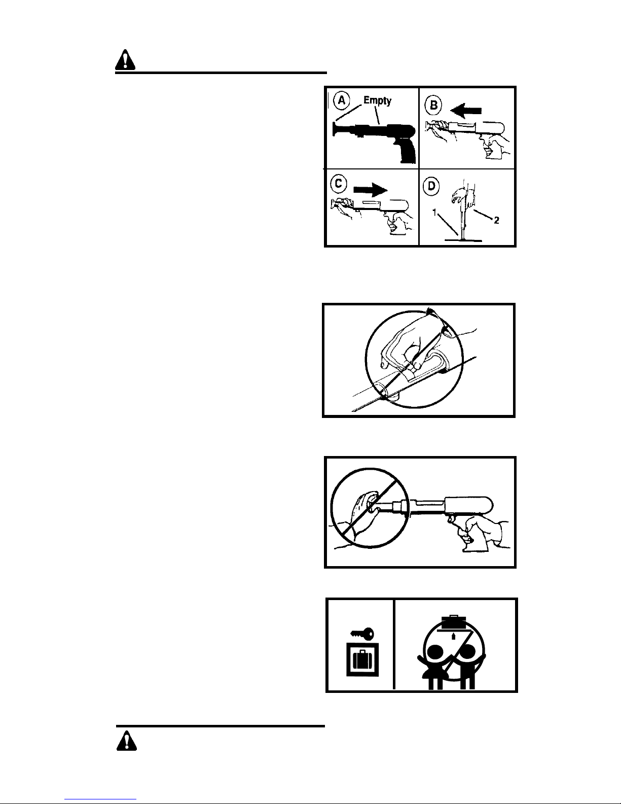
1. Always be sure tool is operating
properly before attempting to
use it. Follow the “Daily
Function Check” shown to the
right and described on page 9.
2. Always load tool using a power
load selected directly from a box
indicating the power load type
and number. Never attempt to use
loose loads that could be
mis-identified.
3. Never carry loose loads in
pockets with pins or other hard
objects.
4. Never load a tool unless you
intend to immediately make a
fastening. Loading a tool and
leaving it unattended in the work
area can result in the tool being
accidentally discharged by others.
5. Never place your hand or any
other body part over the fastener
loading end of the tool. Serious
hand injury could result from being
struck by either a fastener or the tool
piston should the tool be accidentally
fired.
6. Always store the tool unloaded
and keep the tool and the loads
securely locked in a tool box.
Keep keys away from children
and unlicensed persons.
7. Always keep the tool pointed
away from yourself and others.
8. Never carry a loaded tool around
the work area.
9. Never allow anyone not trained to
use the tool.
10.Never engage in horseplay with
the tool.
11.Using the tool in poorly ventilated
areas, cleaning tool or handling
loads may result in exposure to
lead or other substances known
to cause birth defects, and other
physical harm. Have adequate
ventilation at all times and wash
thoroughly after exposure.
ALWAYS DO A DAILY
FUNCTION CHECK BEFORE
LOADING THE TOOL
NEVER LOAD THE TOOL UNLESS
IT IS TO BE USED IMMEDIATELY
NEVER PLACE HANDS OR
BODY OVER MUZZLE OPENING
KEEP TOOL LOCKED & OUT OF
THE REACH OF CHILDREN
Page 6
DANGER
SAFETY INSTRUCTIONS
DANGER
SAFETY INSTRUCTIONS
FAILURE TO FOLLOW
INSTRUCTIONS CAN CAUSE
INJURY TO THE TOOL OPERATOR OR TO BYSTANDERS.
Fastener Driving Safety
1. Only use the tool for fastening
into a suitable base material.
2. Never fire the tool without a
fastener. Firing a tool without a
fastener will cause the piston to
strike the work surface, and may
cause serious injury to you and
others in the work area.
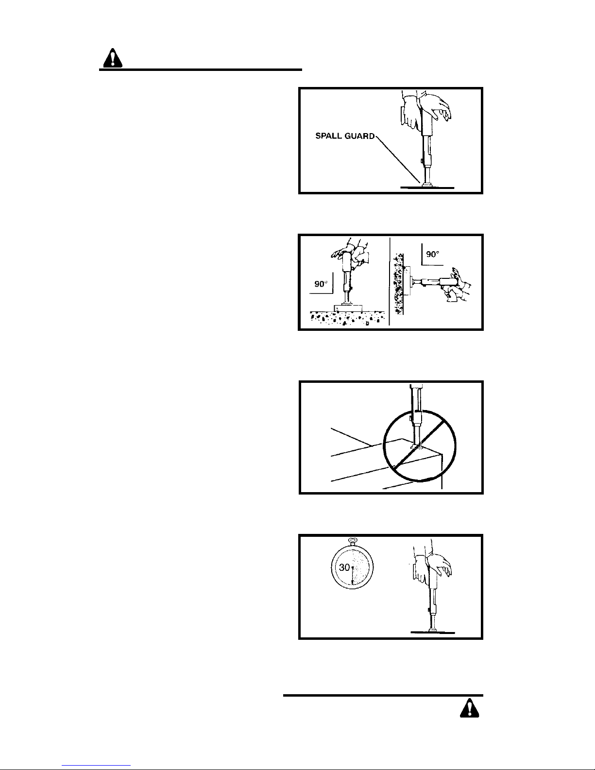
3. Always use the spall guard
whenever possible to minimize
flying particles or debris.
4. Always hold the tool perpendicular to and firmly against the
work surface when making a
fastening. Failure to do so could
allow a fastenerto ricochet.
5. Never attempt to drive a fastener
close to an edge or to another
fastener. See page 8 for guidelines.
ALWAYS FOLLOW THE MISFIRE
PROCEDURE
If the tool does not fire after pull-
ing the trigger, continue to hold the
depressed tool against the work
surface for at least 30 seconds. Then
carefully open the tool, remove the load,
and put it in a can of water or other nonflammable liquid. Never carelessly
discard live loads into a trash container.
If the tool becomes stuck or jammed
with a live powder load, keep the tool
pointed in a safe direction, and immediately tag it, “Danger-defective-do not
use”. Lock the tool in a tool box and call
your local Ramset Distributor for assistance.
USE THE SPALL GUARD
WHENEVER POSSIBLE
ALWAYS HOLD THE TOOL
PERPENDICULAR TO THE
WORK SURFACE
NEVER DRIVE A FASTENER
CLOSE TO AN EDGE
HOLD THE TOOL FIRMLY
AGAINST THE WORK SURFACE
FOR AT LEAST 30 SECONDS.
6
Page 7
FASTENERS / LOADS
FASTENERS / LOADS
7
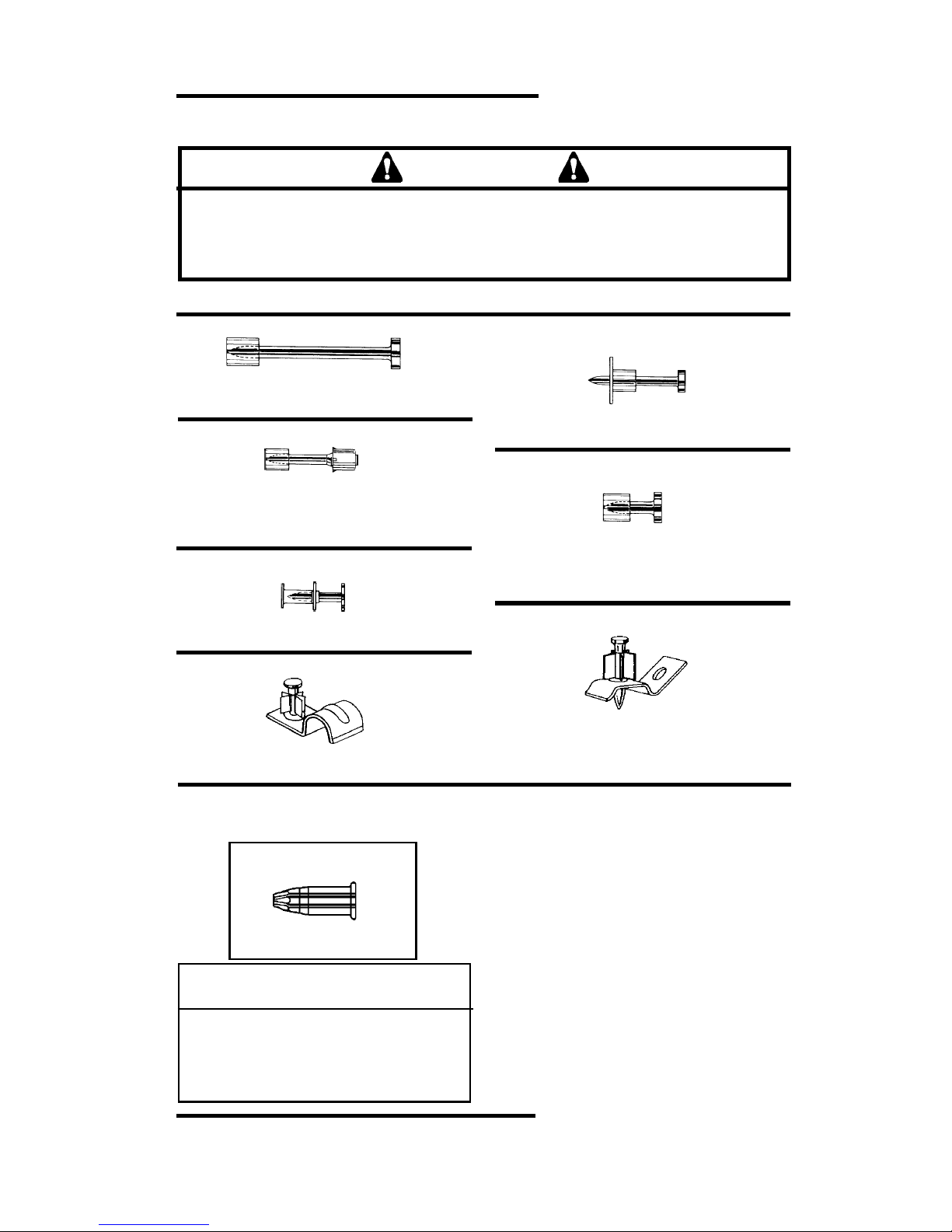
Your Ramset M70 tool uses only the Ramset fasteners and loads shown
below or listed for the tool in the Product Catalog .
DANGER
.300 HEAD PLASTIC FLUTED DRIVE PINS
.300 HEAD PLASTIC FLUTED DRIVE
PINS WITH 7/8" WASHER
1/4"-20 Threaded studs
.300 HEAD TOP-HAT DRIVE PINS
.300 HEAD POWER POINT
PLASTIC FLUTED DRIVE PINS
CONDUIT CLIP ASEMBLIES
For 1/2" and 3/4” Diameter Conduit with
1" premounted fastener
CEILING CLIP ASSEMBLIES
Ceiling Clip with 1" or 1-1/4" premounted
.145 shank pin and Ceiling Clip with 1" or
1-1/4" premounted .150/.180 shank pin.
Never use any other types of fasteners or loads in the M70 tool.
Use of other types of fasteners or loads may cause unintentional load discharge,
damage the tool, cause poor fastening performance, or create a risk of serious
injury to the operator or bystanders.
FASTENERS
.145 Shank Diameter in Shank lengths from
1/2” to 3”
.145 Shank Diameter in Shank Lengths from
1” to 3”
.145 Shank Diameter in Shank Lengths of
1/2” and 1” and thread lengths of 1/2”, 3/4”
and 1”.
.150 Straight Shank in Shank Lengths from
1/2” to 7/8”
.150 / .180 Step Shank in Lengths from
1” to 1 7/8”
.145 Shank Diameter in Shank Lengths from
1/2” to 1”
LOADS
POWER CATALOG LOAD CASE
LEVEL NUMBER COLOR COLOR
1 12 CW Gray Brass
2 22 CW Brown Brass
3 32 CW Green Brass
4 42 CW Yellow Brass
The power level of the loads is indicated by
the number marked on each box, the color of
the box and the color on the tip of each load.
As the number increases, the power level
also increases.
Always perform the center punch test
described on page 3 to test the base
material.
Always make a test fastening using the #1,
Gray, power level first. If more power is
required to set the fastener, use the next
higher power level until the power level
necessary to drive the fastener is reached.
Ramset .22 cal. CW loads are specially made for use in the M70 Tool.
RAMSET CW LOAD
Page 8
FASTENING APPLICATIONS
FASTENING APPLICATIONS
8
FASTENING APPLICATIONS
Your Ramset tool can be used for a wide
range of fastening needs in a variety of
base materials. Reading and following
these important fastening guidelines will
help you get the best results from your
tool, fasteners, and powder loads, as
well as help you perform these fastening
operations safely and effectively.
Powder actuated fastenings are permenant fastenings so attempting to
remove a fastener from concrete or
steel may result in a serious injury.
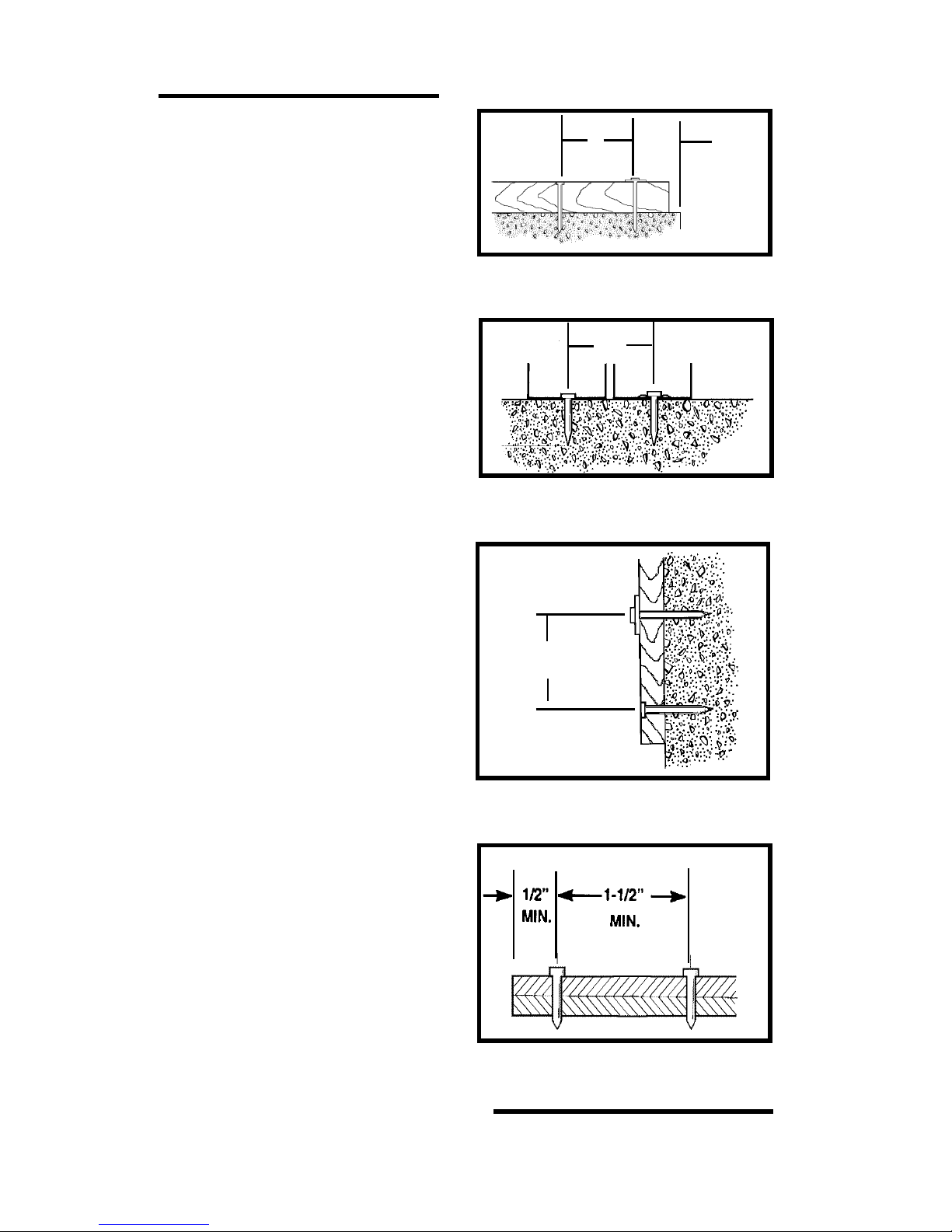
Fastening to Concrete
When fastening into concrete, always
maintain a minimum spacing of 3"
between fastenings and 3" from any
free edge. Concrete thickness should
be at least three times the intended
penetration depth into the concrete. The
primary exception to the 3" edge
distance can occur in a sill plate
application where, by necessity, the
edge distance is reduced.
Driving fasteners too close to an edge
or too close to each other can cause
the concrete edge to fail or fasteners to
fly free.
Fastening to Concrete Block or
to Masonry Walls
While this application is not recommended, when used, it is necessary to
take care to observe a 3” edge distance
to avoid cracking the block and over
penetration of the fastener to avoid a
loss of holding value. Fastenings may be
made into the horizontal joint but not into
the vertical joint.
SPACING
WOOD TO CONCRETE
PENETRATION - THIN GAUGE
METAL TO CONCRETE
➤➤
➤➤
➤
➤➤
➤➤
➤
➤➤
➤➤
➤
➤➤
➤➤
➤
3" MIN.
3" MIN.
➤➤
➤➤
➤
➤➤
➤➤
➤
➤➤
➤➤
➤
3" 3"
MIN. MIN.
SPACING - FURRING
STRIP TO CONCRETE
Fastening to Steel
Your Ramset tool can be used for
fastening on the flat surfaces of
structural steel. When fastening into
steel, always maintain a minimum
spacing of 1-1/2" between fastenings
and 1/2" from any edge.
SPACING
STEEL TO STEEL
Page 9
TOOL OPERATING INSTRUCTIONS
TOOL OPERATING INSTRUCTIONS
9
TOOL OPERATION
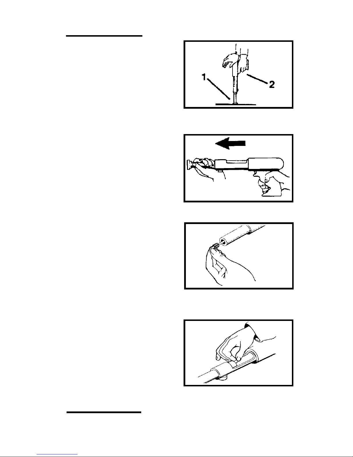
Daily Function Test
Always check the tool first to make
sure that it does not contain a load
or fastener. Test the tool several times
by depressing the muzzle bushing fully
on a hard surface and pulling the trigger.
You should hear an audible click as the
firing pin releases. Let up on the tool and
check to be sure that the barrel has
opened to the semi-closed position.
SLIDE THE BARREL
FORWARD
INSERT FASTENER INTO THE
MUZZLE END OF THE TOOL
WITH THE POINT OUT
OPERATING THE M70 TOOL
1. After checking to be sure that
the tool is not loaded, point it in a
safe direction and pull the barrel
open with a quick forward
motion.This action positions the
piston in preparation for the next
fastening. Use the spall guard every
time possible to minimize the risk of
being struck by flying debris.
2. With finger off the trigger, place
the fastener, point out, into the
muzzle end of the tool until the
point end is inside the muzzle.
NEVER load a fastener with
your finger on the trigger. DO
NOT use excessive force when
inserting a fastener. STOP
immediately if excessive force is
required, inspect the barrel to
find out why the fastener is not
entering the muzzle freely. DO
NOT continue loading unless
the problem is corrected.
3. With the tool pointed in a safe
direction, the barrel fully open, and
your finger away from the trigger,
make sure the chamber is clear
and insert a load into the tool
chamber. Always start with the #1,
gray power level. If the #1 load does
not fully set the fastener, try the
next higher power level until the
proper power level is found.
INSERT A LOAD INTO THE
TOOL CHAMBER
PERFORM FUNCTION TEST
WITH EMPTY, UNLOADED TOOL
Page 10
TOOL OPERATING INSTRUCTIONS
TOOL OPERATING INSTRUCTIONS
10
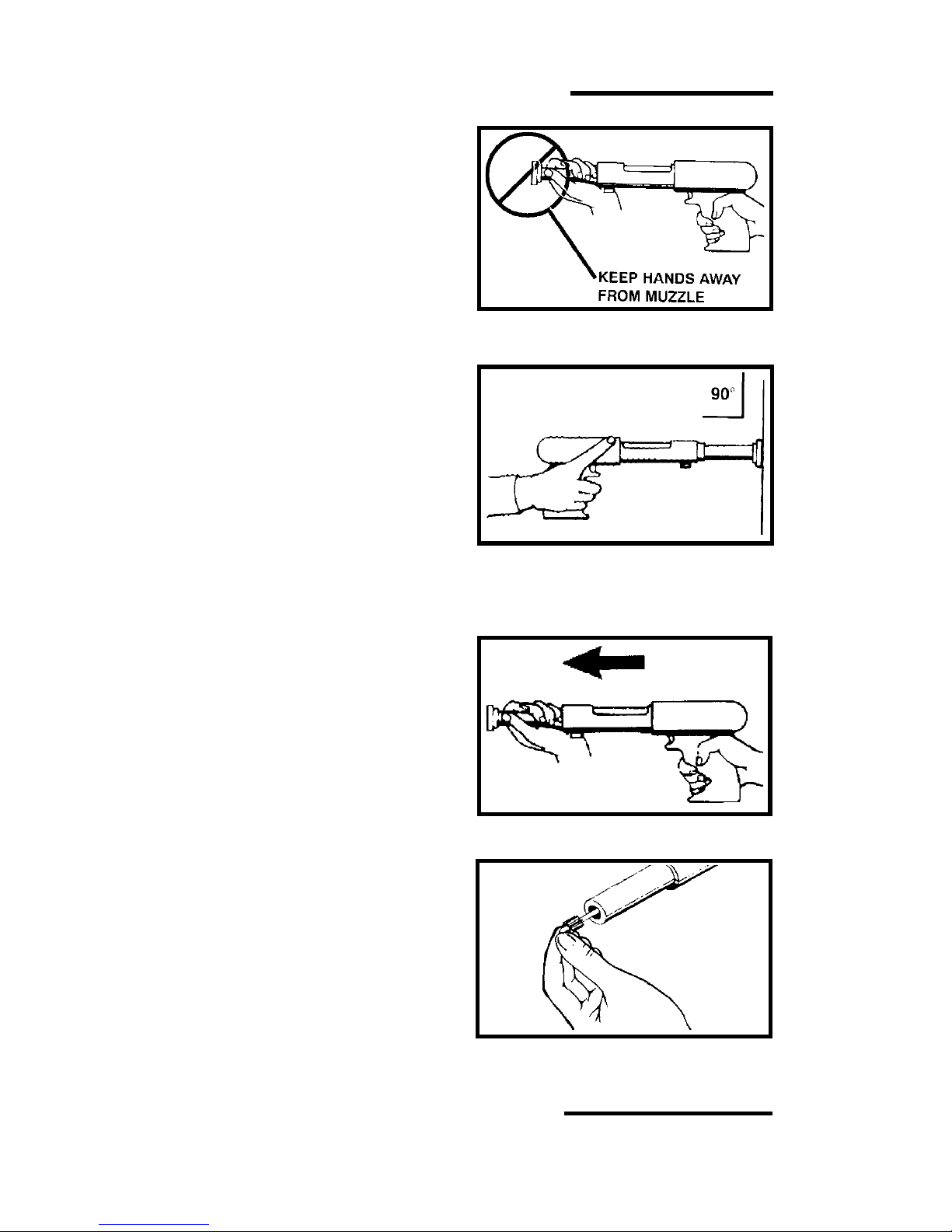
4. Slide the barrel back to the semi-
closed position. Never attempt to
close the tool by exerting force on
the front end of the barrel. Never
place your hand, fingers or any
other body part over the fastener
loading end of the tool.
5. Hold the tool perpendicular (90°) to
the work surface with both hands
and press firmly to fully depress the
tool. Maintain firm downward
pressure on the tool with both
hands and pull the trigger to drive
the fastener. DO NOT DEPRESS
THE TOOL AGAINST ANYTHING
OTHER THAN THE INTENDED
WORK SURFACE. Holding the tool
firmly in place will produce more
consistent fastening quality and
minimize tool wear or damage.
6. After making the fastening, point the
tool in a safe direction, and pull the
barrel forward to cause the barrel
to move to the open position. This
action ejects the fired load case and
properly resets the piston for the
next fastening. Should a fired load
fail to eject, open and close the tool
several times to loosen the load in
the chamber, then remove the load
with your fingers. Never attempt to
pry an unfired load out of the
tool chamber. The load could be
caused to discharge resulting in a
serious injury or death to the tool
operator or to a bystander.
7. Insert another fastener in the
muzzle end of the tool before
inserting a new powder load into the
chamber. Always insert the
fastener into the tool before
inserting the powder load. Keep
your finger off of the trigger until the
tool is in position to drive the
fastener.
Never carelessly discard or
throw unfired powder loads into
a trash container.
HOLD THE TOOL FIRMLY AND
PERPENDICULAR TO THE
WORK SURFACE
INSERT THE NEXT
FASTENER
EJECT THE LOAD
SLIDE THE BARREL BACKWARD
TO THE SEMI-CLOSED POSITION
Page 11

TROUBLESHOOTING
TROUBLESHOOTING
11
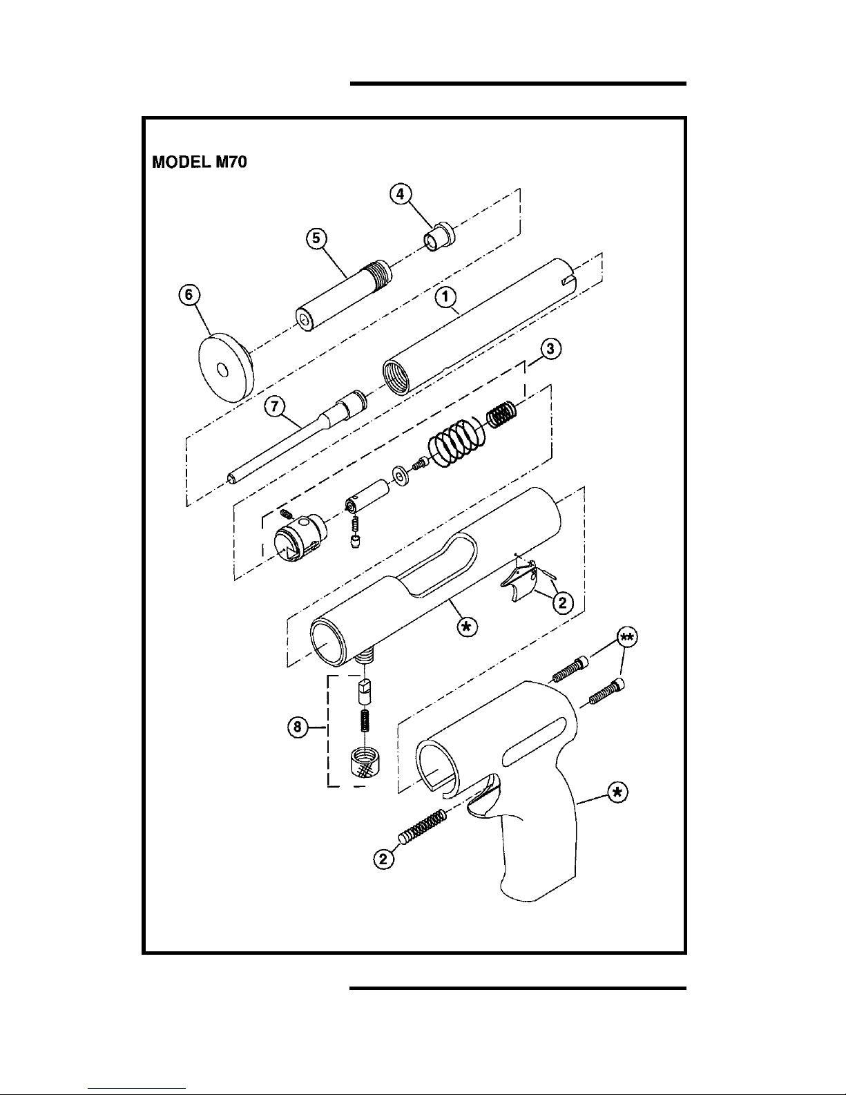
REFER TO PARTS SCHEMATIC FOR PROPER ASSEMBLY OF PARTS
- Overdriving of fasteners - Excessive power - Change to next lower
power level load
color and number.
- Soft base material - Check base material
(see page 3)
- Tool fails to fire - Failure to depress - See “ Tool does not
completely completely depress”
- Excessive dirt buildup - After following misfire
on breech face not allow- procedure,Ask Ramset
ing proper penetration of distributor for assistance
firing pin DO NOT pry load out!
- Firing pin and/or breech - Ask Ramset distributor
damaged for assistance
- Tool does not completely - Misassembled or damaged - Ask Ramset distributor
depress parts for assistance
- Reduction or loss of - Piston not being returned - The barrel must be pulled
power or inconsistent to the full rear position completely open to propfastener penetration erly position the piston.
- Worn or damaged piston or - Replace missing, worn
piston ring or damaged parts.
- Worn or broken pawl - Replace pawl
- Fired load will not eject - Tool not being fully opened - Barrel must be pulled out
fully to allow piston tip to
eject the load case.
- Damaged or bent piston - Replace piston assembly
- Dirt buildup in the breech - Clean breech
- Stuck powder load - Remove barrel assembly
from tool. Unscrew
the muzzle bushing and
remove the piston. Push
out the load with an 1/8”
dia. brass or aluminum
rod. DANGER: If
the load has not been
fired, use extreme care
to avoid causing the load
to discharge.
- Piston stuck in down position - Piston overdriven and stuck in - Tap on a hard surface or
muzzle bushing drive back with brass or
lead hammer. Replace
buffer. Be sure tool is
not loaded and wear
safety goggles.
- Barrel opens too easily - Pawl spring is too weak - Replace spring
- Pawl cap is loose - Tighten pawl cap
- Barrel will not slide open or - Bent piston - Replace piston
is very hard to open - Excessive dirt buildup - Disassemble & clean tool
- Pawl is damaged - Replace pawl
- Debris jammed between barrel - Disassemble & remove
and receiver housing debris
service.
- Chipped or damaged piston tip - Tool not being held squarely to - Grind tip flat (see page
the work surface. 15).
- Unfired load will not eject - Load stuck in chamber - Ask your Ramset
distributor for assistance
Page 12
PARTS SCHEMATIC
PARTS SCHEMATIC
12
Page 13
PARTS LISTING / MAINTENANCE
PARTS LISTING / MAINTENANCE
13
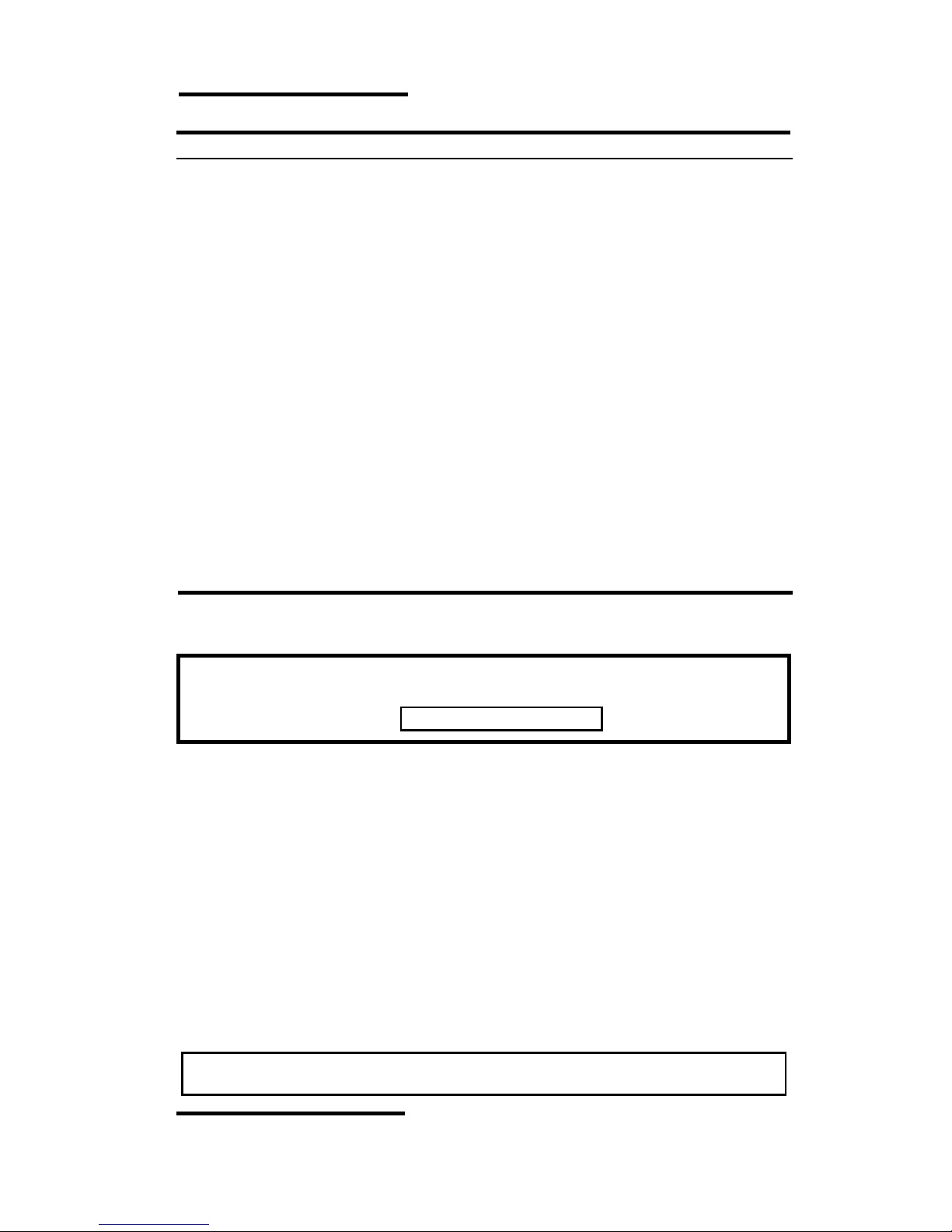
M70 TOOL PARTS LIST
KEY PART NO. DESCRIPTION
1 53202 BARREL
2 533600 TRIGGER ASSEMBLY AND SPRING
3 53330A FIRING MECHANISM ASSEMBLY
4 53109 BUFFER
5 53101 MUZZLE BUSHING
6 53104 SPALL GUARD
8 53115A PAWL ASSEMBLY
9 24853 PISTON RING (NOT SHOWN)
* HANDLE ASEMBLY AND RECEIVER NOT AVAILABLE AS SPARE PARTS
** STANDARD SOCKET HEAD CAP SCREW -1” LONG X 1/4”-28 THREAD
Always make sure the tool is not loaded before performing any service or
repair and always wear safety goggles when cleaning or servicing the tool.
NORMAL CLEANING
All front end parts shown in the disassembly section are to be cleaned daily with a
good detergent oil and wire brush. Remove all dirt and carbon buildup and wipe
parts dry with a clean rag. Check all parts for wear or damage before reassembly
and replace or repair any worn or damaged parts.
COMPLETE CLEANING / GENERAL MAINTENANCE
Heavy use or constant exposure to dirt and debris may require that the tool be
cleaned more extensively. Complete disassembly and cleaning of all parts may be
necessary to restore the tool to normal operation. General maintenance should be
performed every six months or more often if the tool is subjected to heavy use.
Contact your authorized Ramset Distributor for assistance.
ALWAYS FUNCTION TEST THE TOOL AFTER PERFORMING ANY SERVICE.
SEE PAGE 9 FOR DETAILS ON THE FUNCTION TEST.
MAINTENANCE
IMPROPERLY MAINTAINED TOOLS CAN CAUSE SERIOUS INJURIES TO
TOOL OPERATORS AND BYSTANDERS
CLEAN TOOL DAILY
Page 14
DISASSEMBLY
DISASSEMBLY
14
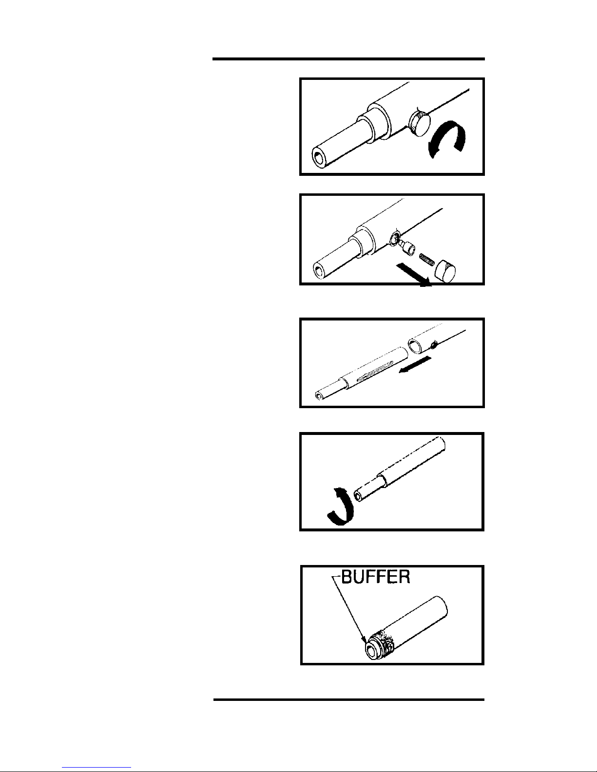
TOOL DISASSEMBLY
1. Unscrew and remove the pawl cap.
If necessary to use pliers, take
care to prevent forming sharp burrs
on the cap which may cause finger
cuts. (Spall gaurd not shown for
sketch clarity).
2. Remove the pawl spring and pawl.
3. Pull the barrel assembly out of the
receiver.
4. Unscrew the muzzle bushing from
the front end of the barrel. Inspect
the muzzle bushing for wear and
end damage.
5. Remove the buffer from the muzzle
bushing and inspect for wear and
damage and replace if necessary. It
is good practice to replace the
buffer anytime the piston is
replaced.
UNSCREW THE PAWL CAP
REMOVE THE PAWL SPRING
AND PAWL
UNSCREW THE MUZZLE BUSHING
AND INSPECT
REMOVE BUFFER AND INSPECT
FOR WEAR AND DAMAGE
REMOVE THE BARREL
Page 15
DISASSEMBLY
DISASSEMBLY
15
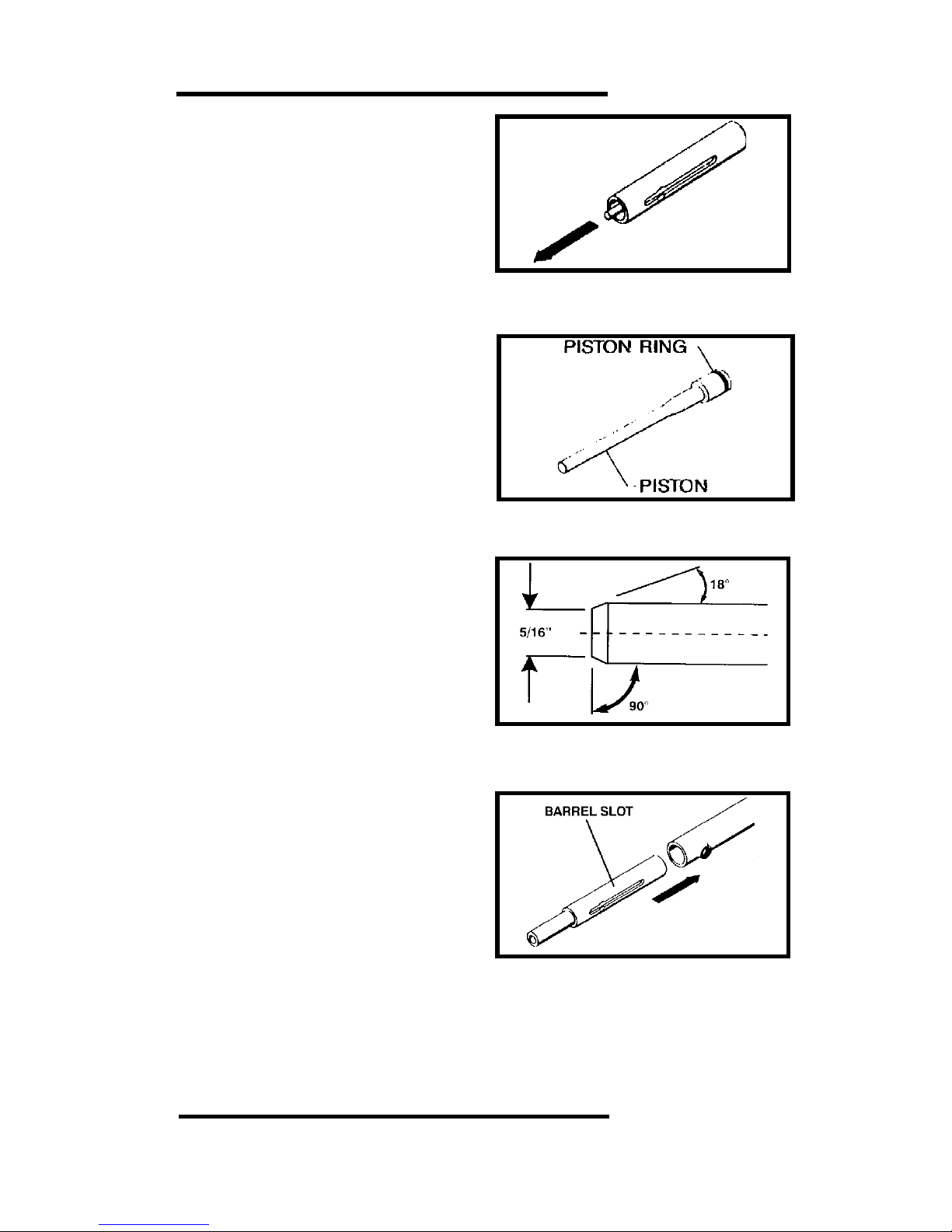
PULL THE PISTON ASSEMBLY
OUT OF THE BARREL
6. Pull the piston assembly out of the
barrel. Check the piston for tip end
damage and that it is not bent.
To repair the tip end of the piston,
refer to the instructions below.
7. Check the piston ring for excessive
wear, breakage or deformation that
would allow it to be less that a tight fit
in the barrel. If the piston assembly is
a loose fit in the barrel, replace it.
8. Inspect all parts for wear or damage
and clean or replace as required.
Use detergent oil and cleaning brush.
Wipe parts dry before reassembly.
WEAR SAFETY GOGGLES WHEN
CLEANING TOOL PARTS.
9. Check the piston tip fpr mushroom-
ing or other deformities, and grind
flat. The tip of the piston must be 90°
to the shank and grinding should only
be done by qualified personnel. The
overall minimum length of the piston
must not be less than 5 3/8”. When
less than this length, the piston must
be replaced to avoid tool damage.
10. Reassemble the tool in the reverse
order of disassembly. Align the
barrel slot with the pawl opening in
the receiver and slide the barrel
assembly back into the receiver.
ALWAYS PERFORM THE DAILY
FUNCTION TEST BEFORE
USING THE TOOL AFTER
CLEANING OR SERVICING.
INSPECT THE PISTON FOR WEAR
AND DAMAGE
GRIND THE PISTON TIP FLAT
AND BEVEL THE EDGE AT 18°
ALIGN THE BARREL SLOT WITH
THE PAWL AND SLIDE THE
BARREL INTO THE RECEIVER
Page 16
WARRANTY
ALL WARRANTIES OF THE PRODUCTS DESCRIBED HEREIN,
EXPRESSED OR IMPLIED, INCLUDING THE WARRANTY OF
MERCHANTABILITY AND FITNESS FOR PARTICULAR PURPOSES, ARE SPECIFICALLY EXCLUDED, EXCEPT FOR THE
FOLLOWING: Ramset will repair or replace, at its sole option, any
tool, part, or fastener which, within 90 days after sale by Ramset,
is found by Ramset to be defective in material or workmanship,
normal wear and tear excluded. THIS IS THE SOLE WARRANTY OF
RAMSET AND THE SOLE REMEDY AVAILABLE TO THE BUYER
AND IN NO EVENT WILL ANY DIRECT OR INDIRECT INCIDENTAL
OR CONSEQUENTIAL DAMAGES, OR ANY OTHER DAMAGES,
BE AVAILABLE.
Copyright 2000 ITW Ramset/Red Head
THE M70 TOOL COMPLIES WITH OSHA REQUIREMENTS
AND WITH ANSI A10.3 SPECIFICATIONS
FOR TOOL REPAIR SERVICE CONTACT YOUR LOCAL
AUTHORIZED ITW RAMSET/RED HEAD DISTRIBUTOR OR CALL
THE ITW RAMSET/RED HEAD TOOL REPAIR DEPARTMENT AT
1-800-354-7432
Wood Dale, IL 60191
(630) 350-0370
Buy With Confidence ....
Buy From Your Authorized Diistributor
© ILLINOIS TOOL WORKS 2000
PRINTED IN THE U.S.A.
REVISED 10/00
 Loading...