


________________________________________________
MINI SKID LOADER
MODEL 500 & 575T “ESTATE SERIES”
________________________________________________
OPERATOR’S MANUAL
________________________________________________
RAMROD Equipment
(A Division of Leon’s Mfg. Company Inc.)
Canada
P.O. Box 5002
135 York Road East
Yorkton, Saskatchewan
S3N 3Z4
Phone: (800) 667-1581
Fax: (306) 782-1884
Email: sales@ramrodequip.com
Website: www.ramrodequip.com
Rev. SEPT 2018


INTRODUCTION
TO OUR CUSTOMER:
RAMROD EQUIPMENT is pleased that you have chosen a RAMROD MINI-SKID.
This loader is a simple, compact power source designed and manufactured to give you years of
dependable service.
Read this Manual carefully before operating the Mini-Skid. It contains the necessary
information for safe and proper operating, routine servicing and preventive maintenance.
We also recommend that you carefully read the Engine Manufacturer’s Manual before operating
the Mini-Skid. Do not neglect the maintenance that is recommended.
The reference to right-hand and left-hand used throughout this Manual refers to the position
when operating the machine, facing forward.
For any additional information required, please refer to your RAMROD Dealer.
© Copyright 2008, Ramrod Equipment Corporation
All rights reserved.
No part of this book may be reproduced or transmitted by any means, electronic or mechanical,
including photocopying, recording or by any information storage and retrieval system, without
written permission of Ramrod Equipment Corporation.
August 2011
Printed in Canada
RAMROD EQUIPMENT
(A Division of Leon’s Mfg. Company Inc.)
CANADA
Box 5002 – 135 York Road East
Yorkton, Saskatchewan
S3N 3Z4
Phone: (800) 667-1581
Fax: (306) 782-1884
Email: sales@ramrodequip.com
Website: www.ramrodequip.com

RAMROD WARRANTY
The RAMROD EQUIPMENT warrants each new RAMROD Mini-Skid to be free from proven
defects in material and workmanship under normal use and maintenance for a period of twelve
(12) months, commencing with delivery to the original buyer. Under conditions of this warranty,
the Mini-Skid must be operated according to manufacturer’s instructions, and by a competent
and careful operator.
This warranty shall not apply to the Mini-Skid on any part thereof, which has been subject to
misuse, negligence, alteration, accident, or used in any way, which, in the manufacturer’s option,
adversely affects its performance.
It is the responsibility of the Buyer, at his expense, to transport the Mini-Skid or any part thereof
in fulfilling this warranty to a designated service shop.
In no event shall the Buyer be entitled to recover for incidental or consequential damages such
as, but not limited to, rental of replacement equipment, loss of profits, and loss of Mini-Skid
fluids and lubricants.
This warranty does not extend to Mini-Skid components such as, but not limited to, engine, tires,
batteries, hydraulic/hydrostatic components which are manufactured by others, and which carry
separate warranties of their respective manufacturer’s.
This warranty is in lieu of all other warranty expressed or implied, and there are no warranties of
merchantability or fitness for a particular purpose.
No representative of the manufacturer, nor the selling dealer has authority to change this
warranty in any manner whatsoever.
Printed in Canada
NOTE: In order for warranty to be in effect, the following warranty
registration forms must be completed and one copy sent to Ramrod
Equipment at time of sale.

Leon's Mfg. Company Inc.
DEALER PRE-DELIVERY INSPECTION & SERVICE REPORT
Owner: Dealer:
Address: Address:
Model: Serial No: Date:
Engine Serial No: Hour Meter Reading:
Item Remarks
( ) Check engine oil
( ) Check hydraulic oil level
( ) Check radiator coolant level
( ) Check battery fluid level
( ) Check tension of engine belts
( ) Check air cleaner hoses & connections
( ) Grease/lubricate all pivot points
( ) Grease/lubricate control lever cross
shafts and linkages
( ) Check all wheel bolts for tightness
(90 ft-lbs)
( ) Check tire pressure
( ) Check drive chain adjustment
( ) Check for loose or missing bolts, nuts,
cotter pins etc.
“Home of Quality Leon & Ramrod Products”
RAMROD MINI-SKID LOADER
Leon's Mfg. Company Inc.
PO Box 5002, 135 York Road East, Yorkton, SK S3N 3Z4 Canada
www.leonsmfg.com www.ramrodequip.com www.lrattachments.com
Ph: 306.786.2600 Fax: 306.782.1884


BUCKETS:
□ 31 inch (787mm)
□ 36 inch (914mm)
□ 42 inch (1067mm)
TIRES:
□ 4” Tires (30” Wide)
□ 8” Tires (30” Wide)
□ 6” Tracks (34” Wide)
□ 9” Tracks (40” Wide)
NEW MINI-SKID WARRANTY REGISTRATION FORM
_____________________ __________________ _____________________
Mini-Skid Serial Number Model Number Engine Serial
Number
________________________________ _______________________________
Name of Owner Name of Dealer
________________________________
Owner’s Type of Business
________________________________ _______________________________
Owners Address Dealers Address
________________________________ _______________________________
Date Mini-Skid Sold Date Mini-Skid Delivered
OPTIONS & ACCESSORIES
RAMROD EQUIPMENT
RAMROD COPY
Please forward to:
RAMROD EQUIPMENT
P.O. Box 5002, 135 York Road East
Yorkton, Saskatchewan, Canada
S3N 3Z4
Phone: (800) 667-1581
Fax: (306) 782-1884


BUCKETS:
□ 31 inch (787mm)
□ 36 inch (914mm)
□ 42 inch (1067mm)
TIRES:
□ 4” Tires (30” Wide)
□ 8” Tires (30” Wide)
□ 6” Tracks (34” Wide)
□ 9” Tracks (40” Wide)
P.O. Box 5002, 135 York Road East
Yorkton, Saskatchewan, Canada
S3N 3Z4
Phone: (800) 667-1581
Fax: (306) 782-1884
RAMROD EQUIPMENT
NEW MINI-SKID WARRANTY REGISTRATION FORM
_____________________ __________________ _____________________
Mini-Skid Serial Number Model Number Engine Serial
Number
________________________________ _______________________________
Name of Owner Name of Dealer
________________________________
Owner’s Type of Business
________________________________ _______________________________
Owners Address Dealers Address
________________________________ _______________________________
Date Mini-Skid Sold Date Mini-Skid Delivered
OPTIONS & ACCESSORIES
DEALER COPY

10

11
BUCKETS:
□ 31 inch (787mm)
□ 36 inch (914mm)
□ 42 inch (1067mm)
TIRES:
□ 4” Tires (30” Wide)
□ 8” Tires (30” Wide)
□ 6” Tracks (34” Wide)
□ 9” Tracks (40” Wide)
P.O. Box 5002, 135 York Road East
Yorkton, Saskatchewan, Canada
S3N 3Z4
Phone: (800) 667-1581
Fax: (306) 782-1884
RAMROD EQUIPMENT
NEW MINI-SKID WARRANTY REGISTRATION FORM
_____________________ __________________ _____________________
Mini-Skid Serial Number Model Number Engine Serial
Number
________________________________ _______________________________
Name of Owner Name of Dealer
________________________________
Owner’s Type of Business
________________________________ _______________________________
Owners Address Dealers Address
________________________________ _______________________________
Date Mini-Skid Sold Date Mini-Skid Delivered
OPTIONS & ACCESSORIES
CUSTOMER COPY


1
TABLE OF CONTENTS
I. SAFETY ........................................................................................................................ 2
Safety Precautions ........................................................................................................... 2
II CONTROL .................................................................................................................... 4
Engine Controls – Briggs 13.5 HP Gasoline .................................................................. 4
Primary Controls ............................................................................................................. 6
Attachment Lock Pins ..................................................................................................... 8
III OPERATION ............................................................................................................... 9
Pre-Starting Inspection and Preperation ......................................................................... 9
Starting Procedure – Gasoline Engine ............................................................................ 9
Shut-Off Procedure – Gasoline Engine......................................................................... 10
Mounting Attachments.................................................................................................. 11
Operational Procedure .................................................................................................. 12
IV MAINTENANCE ...................................................................................................... 16
Engine Maintenance – Briggs Engine ........................................................................... 16
Battery Maintenance ..................................................................................................... 17
Air Filter Maintenance .................................................................................................. 17
Fuels, Lubricants and Capacities .................................................................................. 18
Hydraulic System Maintenance .................................................................................... 19
Final Drive Maintenance............................................................................................... 20
Chain Lubrication ......................................................................................................... 21
Periodic Greasing Details ............................................................................................. 22
Periodic Maintenance and Service Schedule ................................................................ 23
Troubleshooting ............................................................................................................ 24

2
I. SAFETY
IMPROPER OPERATION OF THIS MINI-SKID MAY RESULT IN SERIOUS INJURY.
BEFORE OPERATING THIS MINI-SKID, OPERATORS MUST HAVE PROPER
INSTRUCTIONS, BE FAMILIAR WITH THE SAFETY PRECAUTIONS, AND HAVE READ
THIS AND THE ENGINE MANUFACTURER’S MANUAL THOROUGHLY.
THIS SAFETY ALERT SYMBOL
POINTS OUT IMPORTANT
SAFETY PRECAUTIONS.
OPERATORS MUST UNDERSTAND CAPABILITIES AND LIMITATIONS OF THE EQUIPMENT,
WITH RESPECT TO SPEED, BRAKING, STEERING, STABILITY AND LOAD CHARACTERISTICS
BEFORE STARTING TO OPERATE.
NEW OPERATORS MUST CHECK ALL CONTROLS IN A SAFE, OPEN AREA BEFORE STARTING
WORK.
This Decal Advised Of Actions or
Danger Which Can Cause
READ YOUR OWNERS’S MANUAL AND ALL SUPPLEMENTS BEFORE OPERATING YOUR
MINI-SKID.
WHEN LEARNING TO OPERATE, PROCEED SLOWLY AND CAREFULLY.
DO NOT PLACE FEET UNDER THE PLATFORM.
DO NOT OPERATE ANY OF THE CONTROL LEVERS INCLUDING AUXILIARY POWER TAKE0FF UNLESS YOU ARE STANDING WITH BOTH FEET ON THE PLATFORM AND FIRMLY
HOLDING THE GRIP HANDLES.
DO NOT JERK THE CONTROL LEVERS, USE A STEADY EVEN MOTION.
OPERATE MINI-SKID SAFELY
WARNING
Personal Injury.
Wear Ear Protection
When Engine Is Running.
The Sound Pressure
Level Is: 102 DB for A
Weighted level & 88 DB
For C Weighted Level…
SAFETY PRECAUTIONS
IMPORTANT
This Decal Identifies Procedures
Which Must Be Followed to
Prevent Damage To The
Mini-Skid
Do Not Use the Mini-Skid
During A Thunderstorm
Or When There Is A
Chance of a Lightning
Strike.

3
SAFETY
SAFETY PRECAUTIONS – CONTINUED
KEEP HANDS, FEET AND CLOTHING AWAY FROM ALL MOVING PARTS AND CYLINDERS.
DO NOT ALLOW ANY ONE TO RIDE IN BUCKET.
DO NOT ALLOW MORE THAN ONE PERSON ON THE MINI-SKID AT ANY TIME.
DO NOT ALLOW ANY OTHER PERSON OR ANIMAL CLOSE TO THE MINI-SKID WHILE IN OPERATION.
WATCH FOR OTHER PEOPLE AND EQUIPMENT.
KEEP THE BUCKET LOW WHEN TRAVELLING, TURNING OR CHANGING SPEED.
TRAVEL SLOWLY OVER ROUGH TERRAIN.
BEWARE OF TRENCHES, HOLES AND SIDE SLOPES
DO NOT DRIVE THE MINI-SKID ACROSS STEEP SLOPES.
LOAD, UNLOAD AND TURN AROUND ON FLAT, LEVEL GROUND ONLY.
ENSURE ADEQUATE VENTILATION WHEN USING THE MACHINE IN CONFINED SPACES.
DO NOT CARRY LOAD WITH ARMS IN A RAISED POSITION. ALWAYS CARRY LOADS CLOSE TO THE
GROUND. DO NOT STEP OFF PLATFORM WITH THE LOAD RAISED.
TO AVOID FREE-FALL OF LOAD WHEN LOWERING LIFT ARMS, DO NOT PUSH LIFT ARM LEVER
FULLY FORWARD.
DO NOT EXCEED RATED LOAD CAPACITY.
ALWAYS LOWER THE BUCKET AND SHUT OFF THE ENGINE BEFORE LEAVING THE MACHINE.
AVOID PARKING ON A SLOPE. IF IT IS NECESSARY, PARK ACROSS THE GRADE, GROUND THE
BUCKET AND BLOCK THE WHEELS.
WHEN HOOKING UP ATTACHMENTS TO THE MACHINE, CHECK TO BE SURE LOCK PINS ARE FULLY
ENGAGED.
DO NOT PLACE ANY PART OF THE OPERATOR’S BODY OR ALLOW ANYONE UNDER MINI-SKID ARMS
OR ATTACHMENTS.
DO NOT LUBRICATE, ADJUST OR REPAIR THE MACHINE WITH THE ENGINE RUNNING.
NEVER FUEL A HOT MACHINE.
DO NOT SMOKE WHEN FUELING OR OPERATING THE MACHINE.
ALWAYS READ THE OWNER’S MANUAL FOR PROCEDURES FOR SERVICING AND MAINTENANCE OF
THE MINI-SKID.
REMEMBER, SAFETY FIRST.

4
Ignition Switch
Throttle Control
II CONTROL
It is necessary to become familiar with the location and purpose of each control before
operating the Mini-Skid.
ENGINE CONTROLS – BRIGGS 13.5 HP GASOLINE
Figure 1: Briggs Instrument Panel
Throttle Control – When the Throttle
control lever is pushed fully up the
engine is at “idle”. Pushing the control
down will increase the engine speed.
The lever will catch at fast and pushing
it down all the way operates the choke.
For Throttle positions see Figure 1A-1C.
Ignition Switch – The ignition switch is
a three-position switch. Clockwise from
the OFF position is the ON and start
position.
IMPORTANT
Be Sure Ignition Key Is In Off Position,
Or Even Removed, When The Engine Is
Not Running
IMPORTANT
For Maximum Power While Working,
The Engine Should Be Running At Full
Throttle

5
II CONTROL
Throttle Control Positions
Figure 1A: Idle
Figure 1B: Fast
Figure 1C: Choke

6
II CONTROL
Figure 3: Control Panel
PRIMARY CONTROLS
1. Lift Arm Lever
2. Tilt Lever
3. Auxiliary Lever
4. Left Hand Drive Lever
5. Right Hand Drive Lever
6. Grip Handle
DRIVE LEVERS, Item 4 & 5 Figure 1
The left hand drive lever controls the
wheels on the left hand side and the right
hand drive lever controls the wheels on the
right hand side.
Engage the drive levers slowly because
even a small movement of the levers will
cause motion. All lever movements
should be smooth and gradual. To drive
the Mini-Skid straightforward, move both
control levers forward the same amount.
To drive the Mini-Skid Straight backward,
move control levers back the same
amount.
The Mini-Skid is steered by moving one
lever further forward than the other. To
turn left, move the right lever further
ahead than the left lever; to turn right,
move the left lever further ahead than the
right lever. For the Mini-skid to perform a
spin-turn, or “Skid Steer”, move one lever
forward and the other backward the same
amount.
The “TASKMASTER” features singlehanded steering. For normal operation,
the most comfortable hand position is to
operate the two steering levers with the
Figure 4: Single Hand Steering
palm of the right hand, with the fingers
gripping the grip handle. Flexing the
fingers will allow forward travel, and
simply rotating the palm will allow
normal steering. To reverse, slip the
palm back to the rear of the grip handle,
and use the tips of the fingers to pull the
steering levers backwards.
This position will allow for more precise
control of the unit. At the same time, the
left hand should grip the grip handle for
operator stability, but can also be used to
operate the tilt and dump functions as
required.
NOTE: Be sure to slowly move the
levers to the center (neutral) position
when stopping. The Mini-Skid will stop
INSTANTLY if the operator releases the
drive levers.
Warning
Do Not Move Any Of The Control Levers
Unless Standing With Both Feet On The
Platform And Holding The Grip Handles

7
II CONTROL
Warning
Keep BOTH HANDS On The Grip
Handle At All Times When Operating
The Machine.
Warning
Use Extreme Caution When Stopping. If
The Bucket Or Attachments Is Raised,
The Machine Can Tip.
Keep All Movements Smooth. All New
Operators Must Work The Machine In A
Safe Open Area To Become Familiar
With Its Operating Characteristics.
LIFT CONTROL LEVER – Item 1,
Figure 3
The outside control lever located on the
left hand side controls the lift. Pushing
the lever forward lowers the lift arm and
pulling the lever back raises the lift arm.
In these two positions, the lever is spring
centered to neutral upon release of the
lever.
TILT CONTROL LEVER – Item 2,
Figure 3
The inside control lever located on the
left hand side controls the tilting action
of attachments such as buckets, forks,
etc. Pulling the lever back tilts the
attachments back. Pushing forward on
the lever tilts forward or “dumps” the
attachment. The lever is spring centered
to neutral upon release.
IMPORTANT
Ensure That The Auxiliary Lever Is Kept
In Neutral When Not Being Used To
Avoid Wasting Power. Engine Is
Difficult To Start If Lever Is Engaged.
Hydraulic Oil May Also Overheat
AUXILIARY LEVER – Item 3,
Figure 3
Direction of auxiliary flow and “on-off”
control of attachments is provided by
this lever. When the auxiliary controls
above are turned on, this lever becomes
active. Pushing this lever forward will
operate the attachment in one direction,
while pulling it back will operate the
attachment in the opposite direction.
This lever locks in each position and
must be returned to the center (off)
position manually.

8
II CONTROL
ATTACHMENT LOCK PINS
ATTACHMENT LOCK PINS
The “Taskmaster: tool bar design allows
changing from one attachment to another
quickly and easily, without having to
remove pins.
Attachments are secured on the unit with
two spring-loaded pins. Rotating the
handles on the pins one half of a turn
moves the pins from the locked to the
unlocked position.
To unlock attachments, rotate both pins
so that their handles are both pointing to
the outside of the tool bar, as show in
Figure 5.
To lock attachments, rotate both pins
inwards so that both handles are pointing
towards the center of the machine as
shown in Figure 6. This will allow the
springs to push the pins downwards
through the mounting holes in the
attachment and secure it to the unit.
Figure 5 (Lock Pins Disengaged)
WARNING
The design of the quick attach system is such that
attachments can be lifted and carried without the
lock pins being engaged. Before using any
attachment, check to be sure that the lock pins
are fully engaged and properly in place. The
attachment will fall off when dumped if the lock
pins are not engaged, resulting in possible
damage or injury.
Figure 6 (Lock Pins Engaged)
WARNING
After Hook-Up To Attachment, Check To
Be Sure Lock Pins Are Fully Engaged,
And Locked Into Position.

9
III OPERATION
You can take full advantage of all the features of your RAMROD Mini-Skid by
following the operating information presented here. The Mini-Skid has been designed to
do a lot of work with a minimum of operating fatigue.
Note: For more information regarding engine starting and operation, refer to your engine
“Owner’s Manual”.
PRE-STARTING INSPECTION AND PREPARATION
Before you start the Mini-Skid for the first time each day,
perform the following checks and service:
1. Check engine crankcase oil level.
2. Check engine fuel and open fuel
shut-off valve if closed.
3. Check Hydraulic fluid level in
tank.
4. Check for fuel, engine oil or
mounting pins, nuts and bolts,
safety shields and decals for
possible failure or looseness.
6. Check that all controls are in the
neutral position.
hydraulic leaks. –WARNINGNever check for hydraulic leaks
with your bare hand. Highpressure fluid could penetrate
your skid and cause injury.
5. Visually inspect all hoses, lines,
fittings, tires, pivot points,
Do Not Move Any Of The Control Levers
Unless Standing With Both Feet On The
Platform And Holding The Grip Handles
WARNING
STARTING PROCEDURE – GASOLINE ENGINE
1. Push the throttle lever down
slightly
2. Engage choke
3. Turn the ignition switch to “ON”
and then through to the “START
position. (If the engine fails to
start by cranking for 10 seconds,
wait 5 seconds before trying
again.
4. As the engine warms up, push
back the choke control gradually.
5. Set the throttle lever for idling
speed. Avoid excessive engine
speed during warm-up.
6. To restart a warm engine – move
throttle control slightly and turn
ignition key to “START”.
IMPORTANT
Do Not Crank Engine With Starter For More
Than 10 Seconds At A Time, As This Will
Overheat The Starter.
IMPORTANT
Ensure The Auxiliary Lever is In Neutral When
Not Being Used To Avoid Wasting Power.
Engine is Difficult To Start If Lever Is Engaged.
Hydraulic Oil May Also Overheat
IMPORTANT
Do Not Put Mini-Skid Under Full Load
Condition Until It Has Had An Adequate Warm-
Up Period.

10
III OPERATION
SHUT-OFF PROCEDURE – GASOLINE ENGINE
1. Park the Mini-Skid on level ground.
If it is necessary to park on a slope,
park across the grade and block the
wheels.
2. Lower the lift arms and ground the
bucket.
3. Return throttle control to “idle”
position, and allow engine to idle for
a short while.
4. Ensure Auxiliary & Control levers
are in neutral position.
5. Turn ignition key off, and remove
key.
IMPORTANT
Be Sure Ignition Key Is In OFF Position
Or Even Removed When The Engine Is
Not Running.
11
III OPERATION
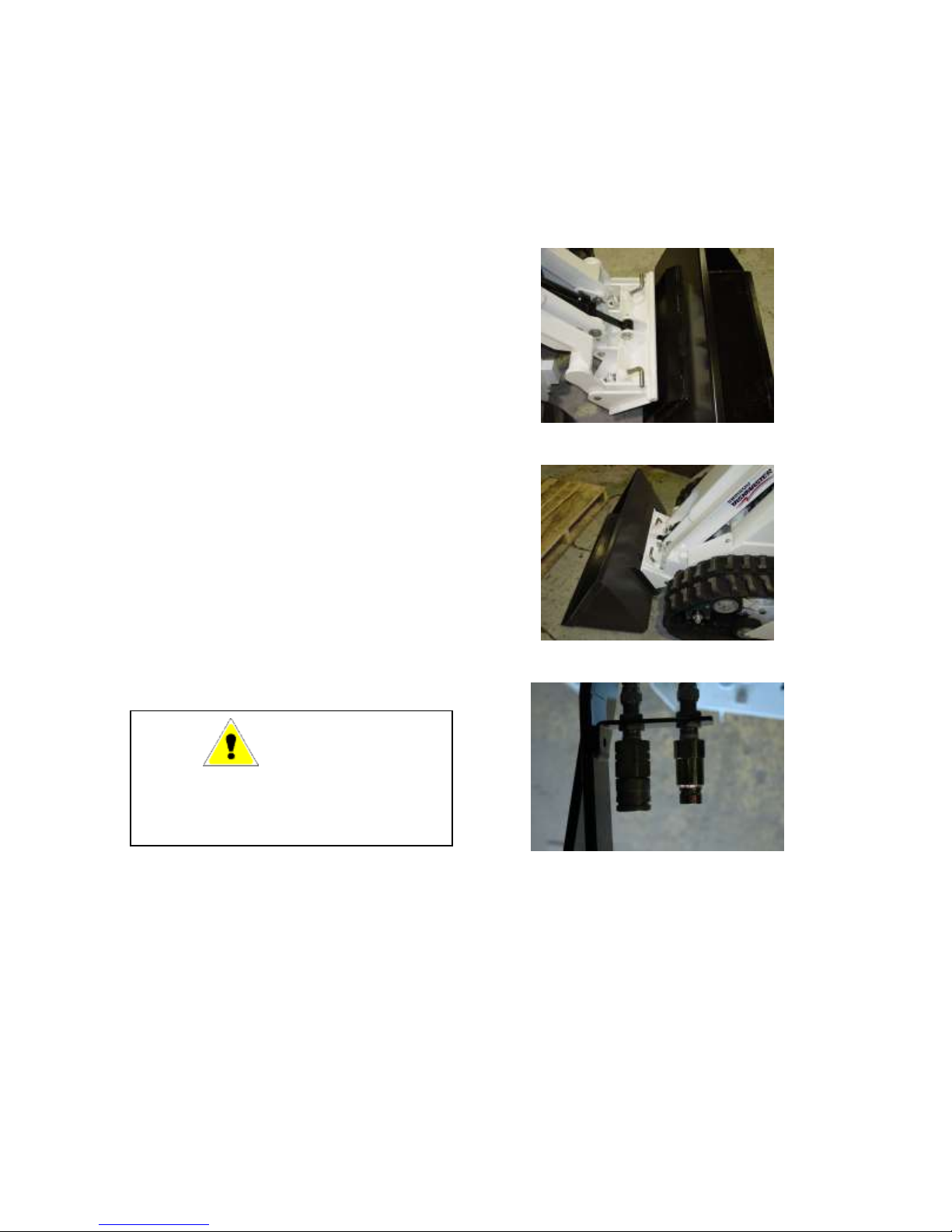
MOUNTING ATTACHMENTS
INSTALLATION OF ATTACHMENT
1. Rotate Lock Pins to the unlock
position (handle pointing outwards).
2. Tilt the attachment frame forward as
show in Figure 7, so that the top
round edge of the attachment frame
will fit under the lip of the
attachment.
3. Drive into the attachment, raising the
arms so that the top of the
attachment frame slips under the lip
on the attachment, and attachment
lifts slightly.
4. Using the tilt cylinder, roll back the
attachment so it drops into place, as
shown in Figure 8
5. Rotate the lock pins to the locked
position (handles facing inwards),
and check that the lock pins are fully
inserted through the lock holes in the
attachment.
6. Connect attachment hydraulic hoses
(if required) to the quick couplers as
shown in Figure 9.
back and forth, and disconnect the
attachment.
Figure 7
Figure 8
WARNING
After Hook-Up To Attachment, Check To
be Sure Lock Pins Are Fully Engaged
and Locked Into Position
REMOVAL OF ATTACHMENT
1. Lower lift arms and tilt forward on
the attachment so that the attachment
is resting on the ground.
2. If attachment is hydraulically
equipped, stop the engine, relieve
hydraulic pressure in the attachment
lines by shifting the auxiliary lever
Figure 9
3. Rotate the lock pins to the unlocked
(handles pointing outwards) position.
4. Start engine, tilt the attachment
mount frame clears that lip on the
attachment, and back the Mini-Skid
away from the attachment.
12
III OPERATION
OPERATIONAL PROCEDURE
Mini-Skid operational procedure and suggestions in this manual are based on the use of a bucket.
Operating procedure and suggestions for such other attachments as dozer blade, posthole auger,
trencher, rock hammer, etc., are included in the respective attachments bundle.
OPERATING SUGGESTIONS
1. Install an attachment (bucket). Drive
carefully to a clean and level area and
practice operating the Mini-Skid at a
slow rate until familiar with the
operation of all controls.
2. Hydraulic power transmission is
instantaneous. When using the drive
levers, sudden movement will result in
acceleration to full speed and a very
jerky ride. Use smooth and gradual
movements when using the drive levers.
3. For efficient operation of the Mini-Skid,
Keep the work area small, and as level
as possible.
4. Decrease cycle time by “SKID” turning
rather than backing up, using a slow
turn, then going forward.
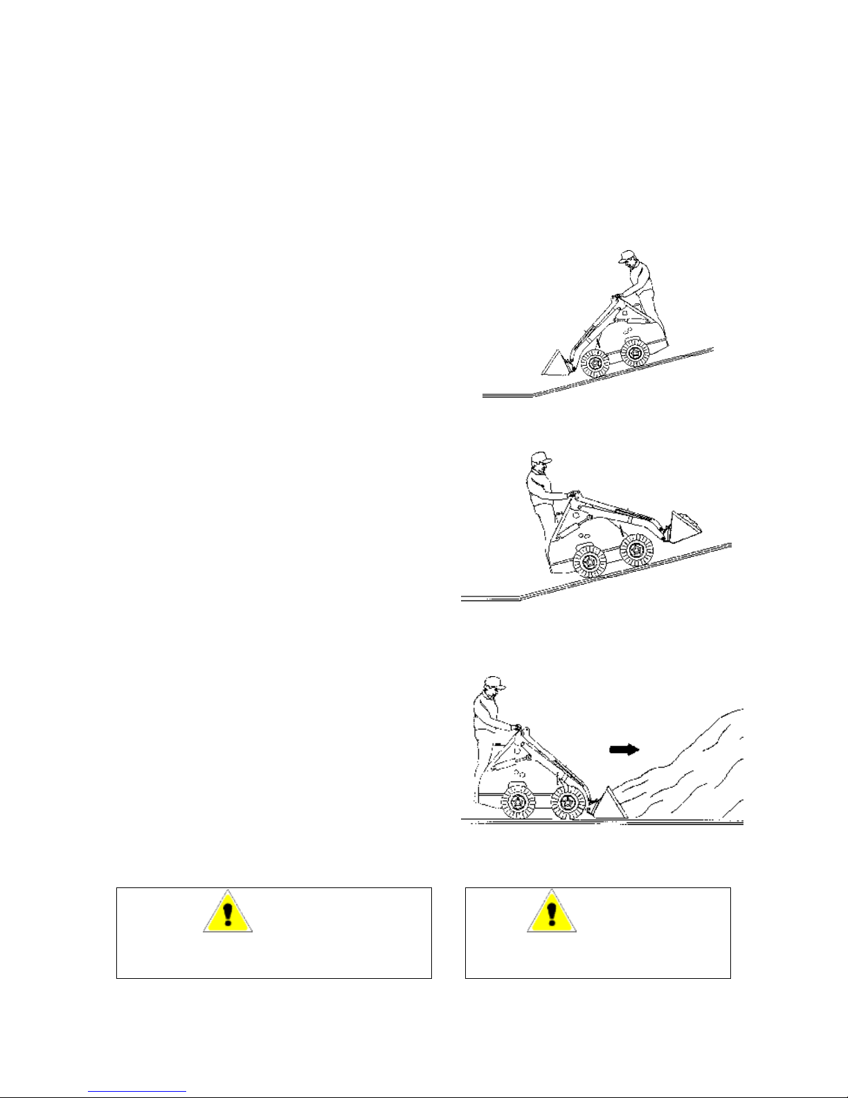
5. When driving on slopes keep the
heaviest end of the Mini-Skid upward.
When driving on a slope with an empty
bucket, back up the slope in reverse, and
drive down a slope forward as in Figure
10. When driving on a slope with a
load, drive up the slope forward and
back down the slope in reverse as in
Figure 11.
6. Fill the bucket to rated capacity.
Turning is easier with a full load than
with a partial load.
7. To increase machine life, let the engine
warm completely before starting
operations each day. Avoid “overloading” or “lugging” the Mini-Skid.
Figure 10 – Empty Bucket
Figure 11 – Full Bucket
Figure 12
WARNING
Always Carry The Bucket Low While Moving. Drive
Directly Up And Down Instead of Across A Slope
WARNING
If Operating Mini-Skid Indoors, Make Sure
Building Is Well Ventilated.
13
III OPERATION
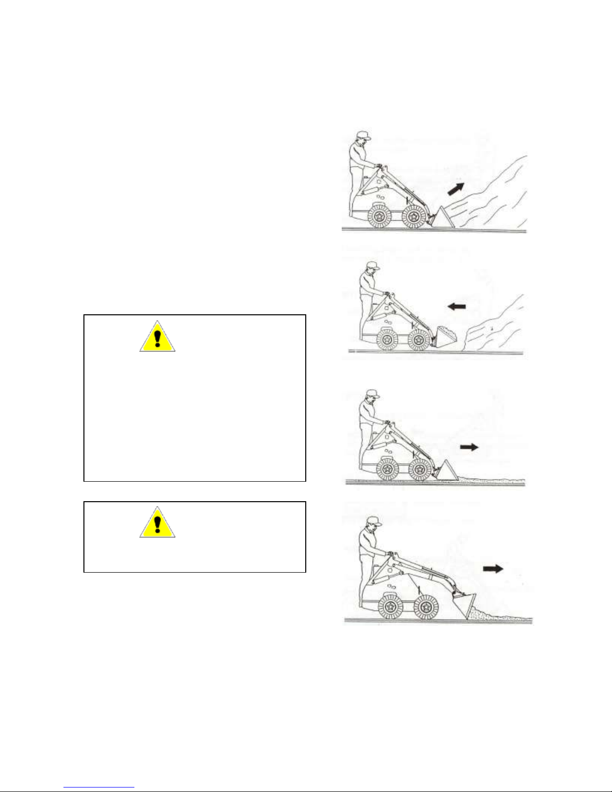
FILLING AND DUMPING A BUCKET
1. Approach the pile with the lift arms fully
down and bucket cutting edge just
skimming the top of the ground as in
Figure 12.
2. As soon as the bucket is full, tilt bucket
back and back away from the pile, as
shown in Figure 13 and 14.
3. When dumping, raise bucket high
enough to clear stockpile or sides of
container being loaded.
4. Drive slowly forward until bucket is
over dumping area and tilt bucket
forward until it completely empties.
5. Tilt bucket, back up if necessary to clear
container side and back away.
driving slowly forward or
stopping the machine.
Figure 13
WARNING
Use Extreme Caution When Stopping. If
The Bucket Or Attachment Is Raised The
Machine Can Tip. Keep All Movements
Smooth and Gradual When Maneuvering
With Lift Arms Raised. Do Not Cross
Obstructions With Arms Raised. All New
Operators Must Work The Machine In A
Safe Open Area To Become Familiar With
Its Operating Characteristics.
WARNING
Never Step Off The Operator Platform With
The Load Raised
DIGGING WITH A BUCKET
1. Lower lift arms fully and tilt bucket
forward until cutting edge is on the
ground.
2. Drive Machine forward slowly and
continue to tilt bucket forward until it
enters the ground to desired depth and
then tilt it back a small amount to keep
an even depth, as show in Figure 15.
3. Continue driving forward until bucket is
full and then tilt bucket fully back while
Figure 14
Figure 15
Figure 16
LEVELING
1. To spread material on uneven
ground, raise lift arms and tilt
bucket forward while driving
slowly forward, as shown in
Figure 16.

14
III OPERATION
1. To level a filled area, tilt bucket
forward and drive machine
backwards to drag bucket and spread
material, as shown in Figure 17.
2. Another method of leveling is to
travel forward with bucket down and
level, full of material and pushing
excess into low areas. Depth is
controlled by tilting the bucket
slightly up or down, as in Figure 18.
Figure 17
Figure 18
2. Tilt bucket forward as soon as it
reaches the edge of the hole and
when necessary raise the arms to
empty the bucket.
TRANSPORTING THE MINI-SKID
Important
Never Tow The Mini-Skid Damage May
Result.
When the machine is transported on a
truck or trailer, proper ramps must be
used for loading.
A Mini-Skid with an empty bucket, or
no attachment should be driven
backwards up a ramp onto the trailer or
forward down a ramp, as shown in
Figure 20.
After the Mini-Skid is driven onto the
transporting vehicle, lower any
attachments, and install chains to hold
Mini-Skid from moving during sudden
stops or when traveling up and down
grades.
Close the fuel valve when the Mini-Skid
is to be transported. Vibration during
transport could cause the carburetor to
flood.
Figure 19
BACKFILLING
1. When filling a trench or a hole, drive
up to the hole with bucket low or
push material up to edge, as in
Figure 19.
Figure 20
WARNING
When Transporting On A Road Or
Highway During The Day Or At Night,
Be Sure That The Trailer Is Equipped
With Lights And Signs As Required By
Law.

15
III OPERATION
LIFT ARM SUPPORT DEVICE
Your Mini-Skid is equipped with a lift
arm support device. This is bolted on
the right side of the Mini-skid under the
front cover as in Figure 21. Note: To
remove lift arm support device there is a
nut on the underside of the frame.
In order to safely work underneath the
lift arms remove the support device from
the leveling arm and remove any
attachment from the Mini-Skid. Raise
the lift arms to their maximum extension
and place the support device onto the lift
cylinder of the Mini-Skid as in Figure
22. Lock the support in place using the
bolt that attached it to the frame.
Ensure the machine is shut off before
performing any work on the Mini-Skid.
After completing work on the Mini-Skid
remove the support device from the lift
cylinder and replace it on the leveling
arm.
Important
Never Lower The Lift Arms With The
Support Device In Place. Damage To
The Lift Cylinder Will Result.
WARNING
Before Performing Any Work
Underneath The Mini Lift Arms Remove
Any Attachment And Raise The Lift Arm
To Full Height. Use The Lift Arm
Support To Lock The Arms In The
Raised Position
Figure 21
Figure 22

16
Hydraulic Oil
Filter
Battery
Air Filter
Oil Filter
Fuel Tank
Oil Filler/Dipstick
Hydraulic Oil
Filler
IV MAINTENANCE
ENGINE MAINTENANCE – Briggs Engine
For proper engine maintenance, refer to your Engine Owner’s Manual. This pertains to
all applicable maintenance on your engine. Maintenance with respect to fluids and
lubricants are included in the “Periodic Maintenance and Service Schedule” in your
Manual.
To Access Engine Compartment, remove louvered front panel held in place by four bolts.
Figure 23
Figure 24: Briggs Engine

17
IV MAINTENANCE
BATTERY MAINTENANCE
NOTE: Check the battery hold down bracket for tightness. Do not over tighten. Remove any
acid corrosion from the battery terminals and cables with a baking soda and water solution. Coat
the terminals with a high temperature grease.
The battery is found under the front cover next to the engine as in Figure 24.
AIR FILTER MAINTENANCE
The air filter is located under the red cover on the right side of the engine as in Figure 24.
To access the air filter open the plastic cover on the engine as in Figure 25. The air filter then
pulls out for inspection and replacement.
Figure 25

18
COMPONENT
TEMPERATURES
TYPE OF
LUBRICANT/FLUID
CAPACITY
Litre (US. Gals.)
Engine Oil
See engine owners
manual
See engine owners
Manual
See engine owners
manual
Fuel Tank
All Temperatures
Gas – Regular
30 Litre (8 US gal.)
Hydraulic Oil
Reservoir
All Temperatures
ISO 46 Anti-Wear
Hydraulic Oil
37 Litres
10 US Gal.
IV MAINTENANCE
FUELS, LUBRICANTS AND CAPACITIES
The service obtained from your Mini-Skid is greatly affected by the quality of the
petroleum products used in it. It requires only common products, which are
commercially available through the outlets of major refineries. The following chart
shows which lubricant to use in the various components of the Mini-Skid.
WARNING
Never Add Fuel To A Mini-Skid When
The Engine Is Running Or Is Hot.
The full tank is located on the back side
of the Mini-Skid above the operators
stand as in Figure 26.
Hydraulic oil filler location: Under front
cover as in Figure 24.
Oil filler location: On back left side of
engine as in Figure 24.
WARNING
Do Not Service Mini-Skid While Engine
Is Running.
Figure 26

19
IV MAINTENANCE
HYDRAULIC SYSTEM MAINTENANCE
HYDRAULIC OIL LEVEL CHECK
1. Ensure that the Mini-Skid is standing
level, the lift arms are down and the
tilt cylinder is closed.
2. Remove the oil cap, and check the
level. If oil is apparent, the level is
satisfactory.
3. If necessary add the proper type and
grade of oil.
NOTE: These units are equipped with a low
hydraulic warning indicator. Do not operate if
this indicator is lit.
CHANGING HYDRAULIC OIL
1. The hydraulic oil drain is accessed
by removing the bottom cover plate
as shown in Figure 27. Note: place
unit on blocks or stand for easier access.
2. Remove drain plug (Figure 28) to
drain oil.
3. Remove pump charge line, shown in
Figure 29, to allow tanks to drain
completely. Note that some oil will
empty from this line, so ensure it is
placed to drain into a container.
4. Replace drain plug and refill
reservoir with clean oil. Note: pump
charge line must be undone as per
step 2 in order for the front
hydraulic reservoir to fill completely.
5. Once both reservoirs are filled with
oil, reconnect the pump charge line
and tighten.
6. Start the engine and check for leaks.
CHANGING OIL FILTER
1. To access filter, remove the front
cover.
NOTE: when changing filter, it is
recommended the bottom cover plate be removed
and a container placed under the rear of the
opening to collect any spilled oil.
Figure 27
Figure 28: Drain Plug
Figure 29: Charge Line (left side)
20
IV MAINTENANCE
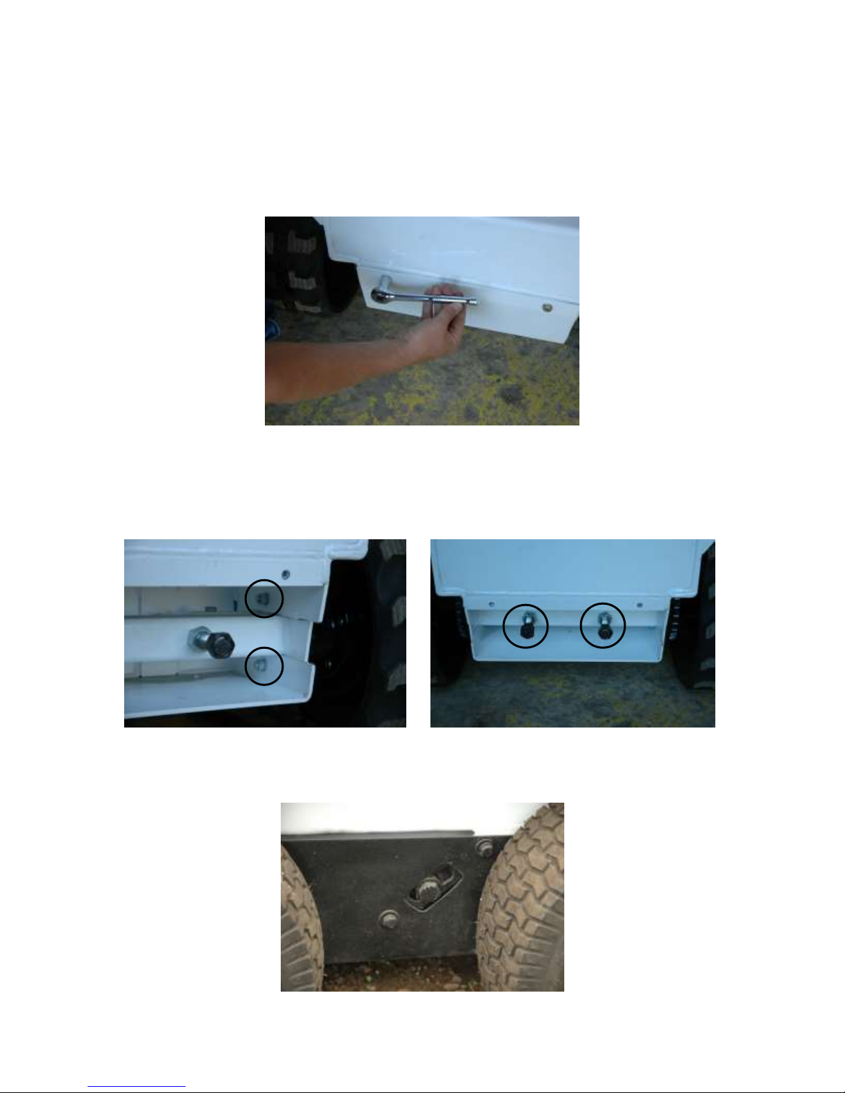
FINAL DRIVE MAINTENANCE
To access front axle adjustment, remove the front lower cover plate held in place by two bolts as
in Figure 30.
Figure 30
To adjust the front axle loosen the two bolts (Figure 31) found on both the right and left
side. Then loosen the jam nuts and use the two long threaded rods (Figure 32) to adjust
axel position accordingly.
Figure 31 Figure 32
There is an idler located behind the cover in between the drive wheels (Figure 33).
Figure 33
NOTE FOR TIRE OPTION:

21
Ambient Temperature
Lubricant Rating
Celsius
Fahrenheit
SAE
BS 4231
-5 to +5
23 to 41
20
46 to 68
5 to 40
41 to 104
30
100
40 to 50
104 to 122
40
150 to 220
IV MAINTENANCE
CHAIN LUBRICATION
For best life drive chains should be lubricated every 8 hours, following this schedule can
extend your chain life by as much as 7 times. The manufacturer’s recommendations
(Renold Power Transmission Ltd) for chain lubricant and application are as follows:
Lubricant should be a good quality non-detergent mineral oil (example 10W30). Heavy
oils and greases are NOT recommended as a lubricant. The following table provides a
guide for lubricant viscosity at various ambient temperatures:
For the majority of the above applications a multi-grade 20/50 oil would be acceptable.
Oil should be applied periodically (every 8 hours) with a brush or oil can. The goal is to
keep the chain wet with oil and ensure penetration of the oil into the chain joints.
Applying lubrication by aerosol is also acceptable, but it is important that the lubricant is
approved for use on roller chain.

22
IV MAINTENANCE
PERIODIC GREASING DETAILS
Greasing is an important factor in extending the service life of many items on your MiniSkid including cylinders, axle bearings and pivot pins.
GREASING THE HUBS AND BEARINGS
Only bearing grease such as Darina EP2 grease should be used on the hubs. The rear
hubs on a 1350 machine have grease points located midway along the top of the hubs. A
1350 also has grease points on the bearing blocks located on either side of the front track
wheels and on the track rollers.
When greasing the hubs and bearings care should be taken to avoid over greasing which
can damage grease seals. These points come greased, and require at most 1 or 2 shots of
grease. DO NOT grease until grease squeezes out the side of the seals.
The outside track rollers and front and rear inner rollers can be greased from the side of
the machine. To grease the central inner track roller raise the lift arm and lock it in place,
the central roller can then be accessed from the front of the machine. It may be necessary
to move the machine backwards or forwards to access all the roller grease zerks.

23
Item
Manual
Service Required
8 or
Daily
25 or
Weekly
50 or
Bi-
Weekly
100 or
Monthl
y
1000 or
Annually
Engine Oil
Engine
Manual
Check level of engine oil and
top up if necessary
X
Engine Fuel
Ramrod
Manual
Check level, and if
necessary, top up.
X
Hydraulic Oil
Ramrod
Manual
Check level, and if
necessary, top up.
X
Tires and
Wheel Bolts
Ramrod
Manual
Check tire pressure and
wheel bolts (bolts to 90 lb-ft).
X
Decals
Ramrod
Manual
Check if damaged safety or
instruction decals. Replace if
necessary
X
Drive Chains
Ramrod
Manual
Lubricate.
X
Wheel Drive
Chain (s)
Ramrod
Manual
Check and adjust tension if
necessary.
X
Air Cleaner
Engine
Manual
Service element.
X
Battery
Ramrod &
Engine
Manual
Clean and protect battery
terminals.
X
Engine Oil
Engine
Manual
Change oil after first 20
hours of operation or as
indicated in engine manual.
X
Grease Hubs
Ramrod
Manual
Grease hubs and track
rollers, be careful not to over
grease.
X
Engine Oil
Engine
Manual
Replace engine oil.
X
Fuel Filter
Engine
Manual
Clean and dry thoroughly.
X
Spark Plug
Engine
Manual
Clean and check gap.
X
Hydraulic
System
Ramrod
Manual
Check all hoses, tires,
fittings, etc. thoroughly.
Replace if needed.
X
Hydraulic Oil
Filter
Ramrod
Manual
Replace oil filter.
X
Engine Oil Filter
Engine
Manual
Change oil filter.
X
Hydraulic Oil
Ramrod
Manual
Change hydraulic oil
X
IV MAINTENANCE
PERIODIC MAINTENANCE AND SERVICE SCHEDULE

24
SYMPTOM
POSSIBLE CAUSES
POSSIBLE REMEDIES
Starter does not crank engine
Low battery output
Loose or disconnected battery
cable
Recharge or replace battery
Check and tighten all connections
Engine turns over but does not
start
No Fuel in Tank.
Fuel shut-off valve closed
Improper starting procedure
Auxiliary control lever engaged
Spark plug fouled
Fill tank with clean fuel
Open fuel shut-off valve
Refer to starting procedure
Set auxiliary lever to neutral
Check Spark plug gap and clean
or replace spark plug
Noisy hydrostatic system
Air in system
Loose suction line and / or
fittings
Clogged oil filter
Hydraulic oil too heavy
Internal pump or motor damage
Check oil level, add if necessary
Bleed system
Tighten all fittings and
connections
Replace oil filter
Warm up hydraulic oil when too
cold
See your RAMROD Dealer
Erratic or no output on
transmission
Hydraulic oil too heavy
Hydraulic oil level too low
Drive coupling between engine
and pump broken
Use proper viscosity oil.
Check oil level. Add is necessary
Check couplings, replace if
necessary
Loss of hydraulic oil flow from
gear pump
Reservoir low on oil
Drive couplings between engine
and pump broken
Hydraulic gear pump not
functioning
Check oil level. Add if necessary
Check couplings, replace if
necessary
Inspect and repair if necessary
Hydraulic cylinders do not
function properly
Loss of hydraulic flow from gear
pump
Air in System
See above
Bleed system
Oil overheating
Reservoir low on oil
Auxiliary control lever engaged
Setting of relief valve too high or
too low
Check oil level. Add if necessary
Return auxiliary level to neutral
Set to correct pressure
See your RAMROD Dealer
No drive on one side of machine
Primary Chain Failure
Inspect and replace
No drive on one wheel
Secondary Chain Failure
Inspect and replace
Noisy operation
Chains too loose
Chains dry
Tighten chain
Lubricate chain
IV MAINTENANCE
TROUBLESHOOTING
The following chart is intended to help isolate problems and provide possible remedies.
 Loading...