

RAM Mounting Systems h1900, h2200, hx2415, rx3115, 3650 Owner's Manual
...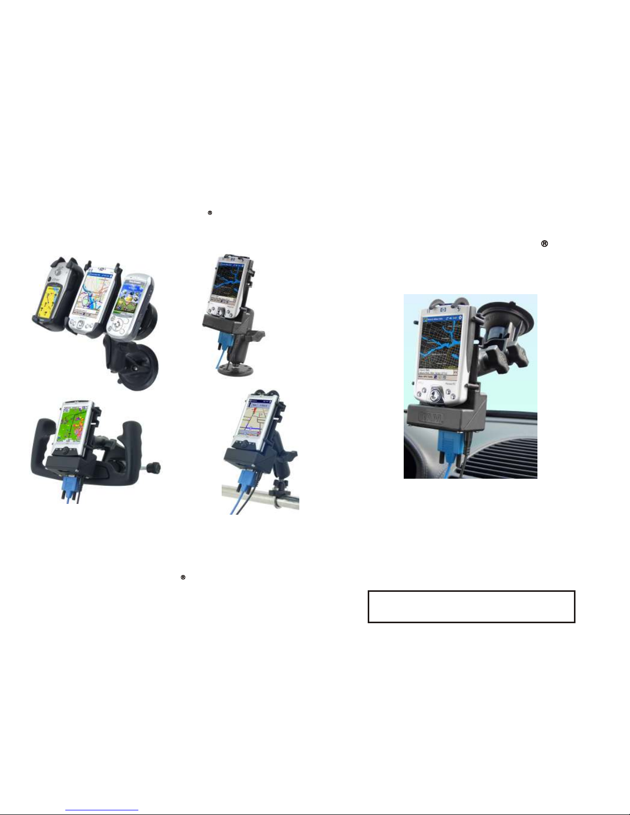
Charging/Serial Docks for iPAQ Handhelds
(Fits All iPAQ Series)
Tel: (206) 763-8361 Fax: (206) 763-9615
Web Site: http://www.ram-mount.com
e-mail: info@ram-mount.com
NPI
National Products Inc.
PLEASE SEE IMPORTANT INSTRUCTIONS
INSIDE BEFORE MOUNTING YOUR IPAQ !
For iPAQ Handheld Computers
™
OWNERS MANUAL
POWERED DOCKING CRADLE
RAM
RAM
RPR-182-CO5-INS
NPI has a Lifetime Warranty on all RAM Mounting Systems
and a Limited Warranty on all electronic components.
Detailed information regarding these warranties may be
accessed on our web site at www.ram-mount.com
PATENTED & PATENTS PENDING
PATENTED & PATENTS PENDING
Provides constant charging and power for iPAQ electronic device in 12
to 28 Volt DC environments. Supplied wire harnesses allow for null or
non-null modem cables. Includes fused coiled power cord with cigarette
lighter plug and straight type power cord for hard wire applications (add
to 2 Amp fused circuit only).
Mounting Systems
exception 1900 series
CONTENTS, DESCRIPTION & ASSEMBLY INSTRUCTIONS
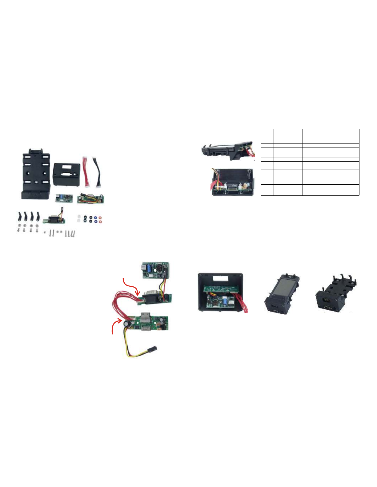
Before proceeding with assembly of powered docking cradle, check the contents of
package to make certain all parts are included. If any parts are missing, please
contact NPI for a replacement part at: support@ram-mount.com
A
B
C
D
E
F
G
H
J
K
L
M
A. 1 qty. RAM Main Plastic Housing
B. 1 qty. RAM PCB Plastic Cover
C. 1 qty. Input / Output Printed Circuit
Board
D. 1 qty. Power Printed Circuit Board
E. 1 qty. IPAQ Male Connector Printed
Circuit Board
F. 1 qty. each Null Modem Wire
Harness (RED), Non-Null Modem Wire
Harness (BLACK),
G. 4 qt. Side Adjusting Retaining Arms
H. 4 qty. each #6-32 X 3/8” Machine
Screws and Nylock Nuts
J. 1 qty. #4 X 1/4” Screw
K. 2 qty. each #4-40 x 3/4” Hex Head
Machine Screw & Nylock Nut
L. 4 qty. #6 X 3/4” Sheet Metal Screw
M. 2 qty. each Spacers: White 1/4”,
Green 3/16”, Black 1/8”, Blue 1/16”,
Red 1/32”
STEP 3 STEP 4 & 5
STEP 1
First determine what type of connection
you require for the serial port. We offer
2 different wire harnesses, a non-nullmodem (Black) and null modem (Red).
To determine what type you require,
contact the manufacturer of your
electronic device that you are attaching
to the powered docking cradle. Once
determined, select the appropriate
colored wire harness and attach it to
the corresponding PCB’s G & H as
shown in the STEP 1 photo. Note, the
ends have different numbers of
connectors so they can’t be reversed.
Attach the 10 qty. connector socket to
the G PCB & the 11 qty. connector
housing to the H PCB. Connect the 3
wire socket on the G PCB to the pins on
the F PCB. Make certain that the label
marked “TOP FACING” is toward you
as shown in the STEP 1 photo.
Step 3 Install C PCB & D PCB into B cover and secure D PCB with J screw.
Make certain that the 3 pins in B cover align with the 3 holes in D PCB. cover with
the 2 screws (C).
Step 4 With iPAQ device still installed in A housing attach B cover with A housing
using L screws. Note; make certain screws are properly aligned and DON’T
OVER TIGHTEN.
Step 5 Attach G side arms with H screws and nuts. With iPAQ device installed in
A housing, G adjust arms and GENTLY tighten screws. Note, insert 4 qty.
business cards between the side arms and the iPAQ device to provide the proper
clearance for easy use.
Your RAM Powered Docking Cradle is now ready for use.
F
E
D
C
11 qty.
Pin
Connector
10 qty.
Pin
Connector
Power PCB
IPAQ Male Connector PCB
Input / Output PCB
Step 2 Before the proceeding look at the pictures in Step 2 and specifically how the
E PCB is attached to A housing. Check the E PCB Application Chart to see what M
washers are required for your iPAQ model. Install the K screws in E PCB along with
the nuts & appropriate colored washers M to properly space the E PCB to align with
the iPAQ device. Make certain to have the K screws, nuts & correct M washers on
the correct side of the PCB. The K nut must have a M washer under it or the PCB
may be damaged. IMPORTANT: DON’T OVER TIGHTEN ANY NUTS, OR
SCREWS IN THE REMAINING STEPS. Insert the iPAQ device into the cradle and
carefully align the E PCB into the mating connector. The 2 qty K hex head screws
will slide into the A housing. Make certain the E PCB is fully engaged into the iPAQ
device and then gently tighten the K nylock nuts.
STEP 2
Model Serial
Pass
Through
Power PCB Washer
Washer For
Nut
h1900 NO NO NO
NA
NA
h2200 YES YES YES WHITE, BLACK BLUE, RED
hx2415 YES YES YES
WHITE, BLUE,
RED
GREEN
rx3115 YES NO YES WHITE, BLUE GREEN
3650 NO NO NO
NA
NA
3955 YES
DATA YES,
POWER NO
YES RED
WHITE,
GREEN, BLUE
h4100 YES YES YES
WHITE, BLACK,
RED
BLUE
h4300 YES YES YES GREEN, RED WHITE, BLUE
hx4700 YES YES YES GREEN WHITE, BLUE
h5555 YES YES YES RED
WHITE,
GREEN, BLUE
h6315 NO YES YES WHITE
GREEN
 Loading...