

Page 1
Item Number
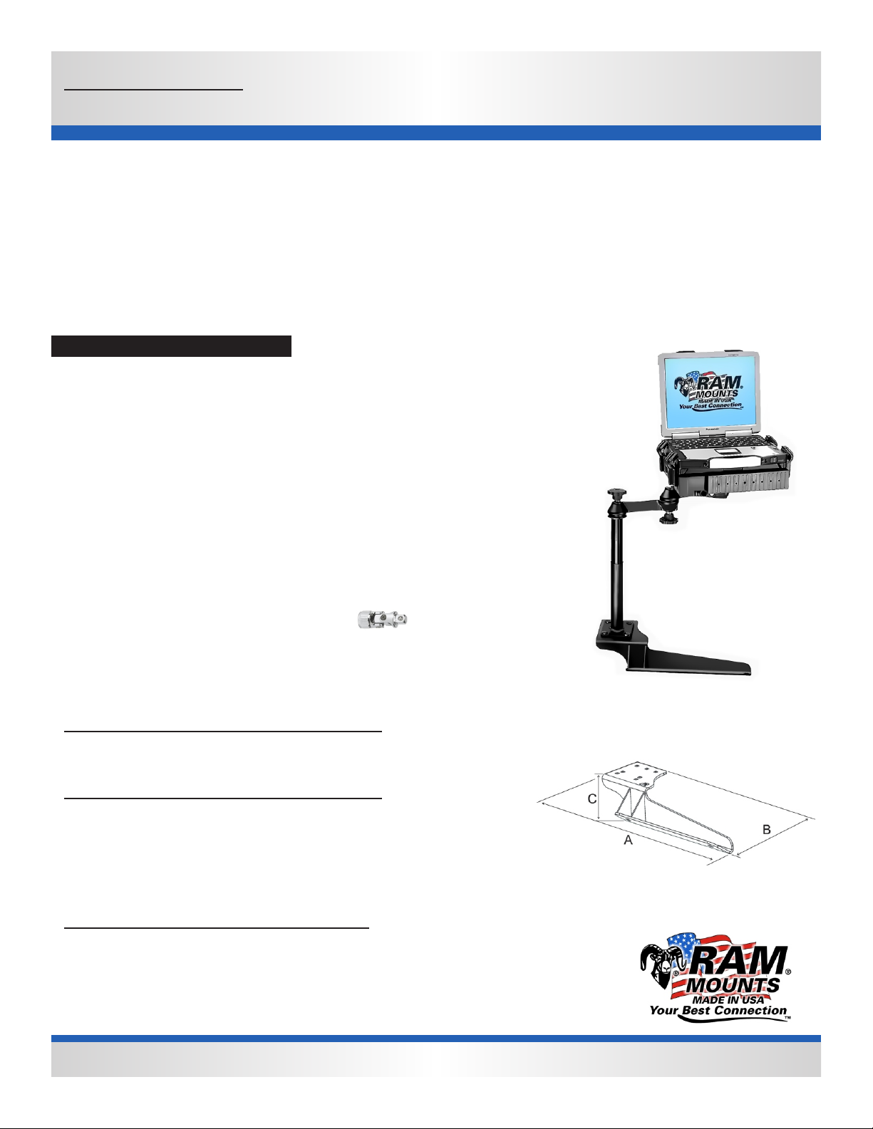
RAM No-Drill TM Seat Bases
RAM-VB-185
Vehicle base for Ford
F-250 - F-750 Superduty trucks with
bucket seats 1999-2013, all cab
types.
Specifications
Placement
Passenger side floor board, over seat frame legs
Seat Configuration
Bucket/Bench
Construction/Finish
Steel/Black Powder coat
Dimensions
A = 18.15", B = 7.05", C = 3.74”
Hole Center = 11.5"
Pole or Pedestal
Purchased Separately
Weight
9.4 lbs.
Tools required for base installation
Ratchet wrench, 19mm socket, and universal joint extension for base
installation. The removal of factory seat leg bolts will require a
13/16” socket.
National Products, Inc.
RAM-VB-185-SW1
Features
Installs with no drilling required
Important note
For model year trucks 1999 through 2010, the use of the one inch
stand offs is required. For 2011 model year trucks, the tallest stand
offs are required to clear the under seat air duct in the extended cab or
crew cab models. For bench seats, it is necessary to expose the hump
side mounting hole and tap it so the supplied bolt has an anchor point.
You’ll need an M12-1.75 tap.
National Products, Inc.
Phone: 206-763-8361
Fax: 206-763-9615
Address: 8410 Dallas Ave S
Seattle, WA 98108
Website: www.ram-mount.com
Email: staff@ram-mount.com
This document, including images, may not be reproduced partly or fully without the expressed written consent of National Products, Inc.
RAM-VB-185
Page 2
Item Number
RAM No-Drill TM Seat Bases
RAM-VB-185
Vehicle base for Ford
F-250 - F-750 Superduty trucks with
bucket or split bench seats 19992013, all cab types.
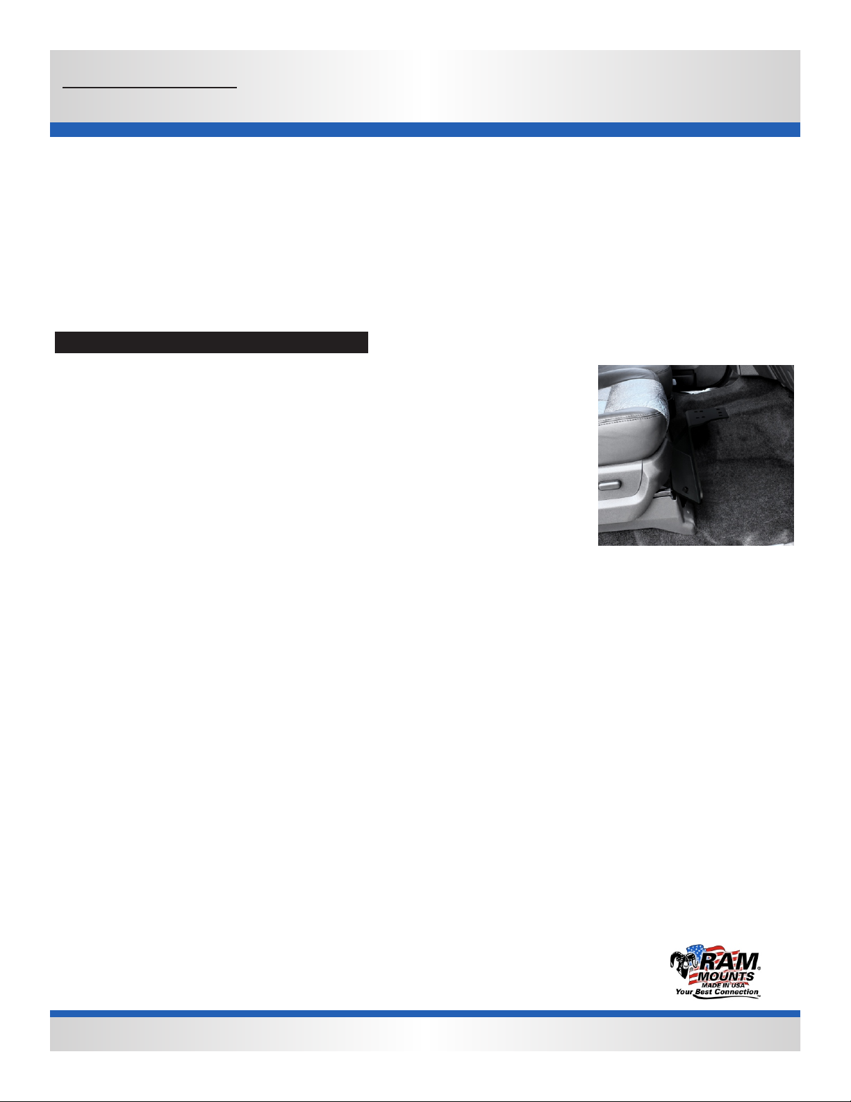
Installation instructions
Bucket Seat Instructions:
Depending on the model year of the truck, you may need a T-55 torx bit or
common hex shaped socket to remove the factory seat leg bolts.
1. Remove the front seat bolts from the passenger side of the seat. This will require the use of the tools
suggested above. Once the bolts have been removed, place the appropriate stand off over the threaded
hole now visible in the seat frame legs. For 1999 through 2010 model year trucks, the one inch tall stand
off is used. For 2011 and newer model years, the 2 3/8” tall stand offs are used.
National Products, Inc.
2. Place the correct stand off over the seat leg holes. Pass the appropriate size bolt through the washer
and then through the hole in the no drill base. Align the base with bolts with the stand offs and start the
thread by hand. Once the bolt thread has been started, use the socket wrench with wobble to begin
tightening the bolts.
Bench Seat Instructions:
1. Remove the front seat bolt from the passenger side of the sea nearest the door. The hole near the hump will have to be exposed as it if often
covered by the flooring material in bench seat models. Make a small u-shaped cut and fold back the flap to expose the hole at the center of the
depression in the flooring. Carefully tap out the exposed hole with an M12-1.75 tap if it is not already threaded. Once tapped, place the black 1.75”
OD washer over this hole. The stand off used in the next step will rest on top of this washer.
2. Place the short, one inch tall stand offs over the hole in the seat frame leg and the hole that is now exposed near the hump. Next, pass the M12-
1.75 x 60 bolt through the supplied washer and then through the metal base at each end.
3. Place the base with the bolts over the stand offs passing the bolts through them and begin tightening by hand the bolts into the floor board.
4. Once the thread has been started, use the socket wrench and appropriate size socket with the wobble to fully tighten these bolts and secure the
base to the floor board.
This kit includes a stabilizer foot package. One or both may be used. This is designed to better support heavier items that may cause the base to
flex or bounce.
The use of the stabilizer foot is recommended to reduce bounce in all applications. Simply replace one of the carriage bolts holding the pole system
or riser in place with the stabilizer foot as shown. You will need a box wrench to tighten the hardware. The part number for the stabilizer foot kit is
RAM-FOOT2-2. Slide the bolt through the foot, slide a lock washer over the thread so it rest on the foot. Place a nut over the thread and tighten to
secure the foot over the head of the bolt. Next, thread a nut over the bolt and slide another lock washer over the bolt. Pass the foot up
through the base from the bottom. Once through the base, slide the flat washer, lock washer, then thread the nut over the bolt. Position foot while
hardware is loose so it is supporting the base off the floor. Once in position, tighten the nut so that it forces the foot down against the floor. Secure
with remaining nut and washers on top.
National Products, Inc.
Phone: 206-763-8361
Fax: 206-763-9615
Address: 1205 S Orr St
Seattle, WA 98108
This document, including images, may not be reproduced partly or fully without the expressed written consent of National Products, Inc.
 Loading...