

Page 1
Item Number
RAM No-Drill TM Seat Bases
RAM-VB-159 & RAM-VB-159-SW1
Vehicle base for the
Chevrolet Avalanche (2007-2013)
Chevrolet Silverado 1500-3500 (2007-2013)
Chevrolet Suburban (2007-2013)
Chevrolet Tahoe (Front Bucket Seats Only) (2007-2013)
GMC Sierra 1500-3500 (2007-2013)
GMC Yukon (2007-2013)
Hummer H2 (2003-2011)
SPECIFICATIONS
Placement
Passenger side, in front, where seat frame meets
floor board.
National Products, Inc.
Drilling Required
None - uses existing seat bolts
Seat Configuration
Bucket
Construction/Finish
Steel/Black Powdercoat
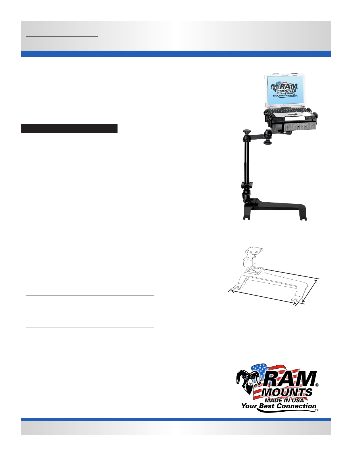
Dimensions
A = 16.875”, B = 9.25”,
Hole Center = 15”
Tools required for base installation
Deep 9/16” hex socket, and socket wrench for base
installation. Tools for complete system
assembly: pliers, phillips screw driver, #10, ½”,
9/16” box end wrench’s.
Pole or Pedestal
Ordered Separately
Weight
7 lbs.
RAM ADJUST-A-POLE TM
Included With Base
Features
Installs in minutes with no drilling required
Won’t interfere with levers, factory-installed console, or 4WD lever
Misc.
Compatible with the 2008 Chevrolet Silverado that contain bucket
Electric seats
Complete Vehicle Mount
RAM-VB-159-SW1
A
RAM-VB-159 shown with riser
attached. Installer may wish to
omit the riser for some applications
B
National Products, Inc.
8410 Dallas Ave S
Seattle, WA 98108
Phone: (206) 763-8361
Fax: (206) 763-9615
Website: www.ram-mount.com
Email: staff@ram-mount.com
This document, including images, may not be reproduced partly or fully without the expressed written consent of National Products, Inc.
Page 2
Item Number
RAM-VB-159 & RAM-VB-159-SW1
RAM No-Drill TM Seat Bases
National Products, Inc.
Vehicle base for the
Chevrolet Avalanche (2007-2013)
Chevrolet Silverado 1500-3500 (2007-2013)
Chevrolet Suburban (2007-2013)
Chevrolet Tahoe (Front Bucket Seats Only) (2007-2013)
GMC Sierra 1500-3500 (2007-2013)
GMC Yukon (2007-2013)
Hummer H2 (2003-2011)
INSTALLATION INSTRUCTIONS
Depending on the trim level of your vehicle, there may be 1 or 2 pieces of plastic trim covering the seat frame bolts used to secure
the seat to the floor board. Also, attaching the adjustable riser to the No-Drill™ base prior to vehicle installation is suggested.
1. Plastic trim must be removed to allow access to seat rail nuts.
2. The inner most seat rail trim piece can be removed by pulling it upward with uniform force. Once removed, you can
see the first of two seat rail nuts to be loosened. Set aside the trim piece to be reinstalled later.
3. The outer most piece of trim has a “D” shaped piece facing the door that can be removed using a small flat head
screw driver. Place the head of the screw driver into the small rectangular opening and gently pry the cover off. Be
careful not to damage the trim. Under this cover is the second seat rail nut that needs to be loosened. Save this
piece of trim along with the first piece you removed.
4. Using a 9/16” deep socket, loosen the two star shaped nuts holding the seat rail to the floor board. Do not remove the
nuts completely as this is not necessary.
5. Once you can lift the seat off the floor board no more than ¼”, slide the base, notches toward the rear and platform
toward the console, between the seat frame and floor board. The base will stop once the back of the notches comes in
contact with the floor studs that pass upward through the seat frame and into the nuts.
6. Once the base is in place, re-tighten the nuts using the 9/16” deep socket to 30 ft lbs.
7. Reinstall the two pieces of plastic trim that were removed earlier.
Please note that one or both pieces of trim covering the front of the seat rails may be raised slightly off the floor as a result of this
installation.
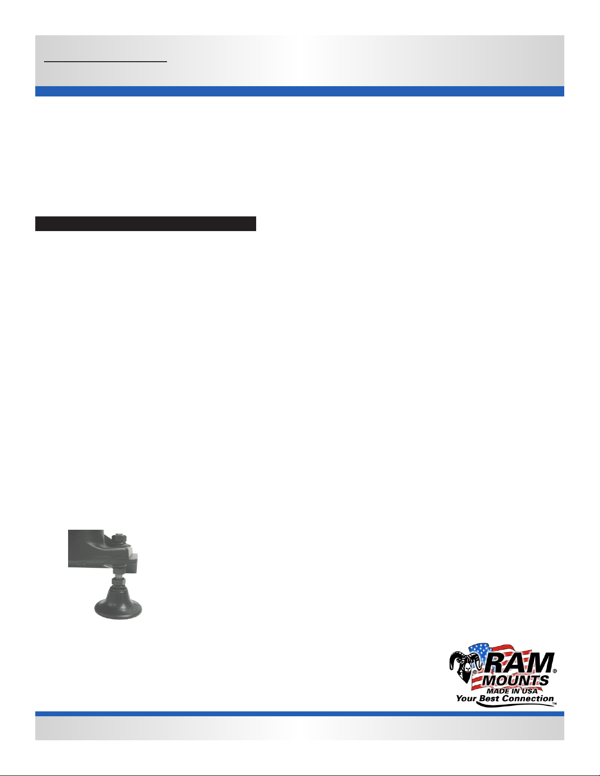
The use of the stabilizer foot is recommended to reduce bounce in all applications.
Simply replace one of the carriage bolts holding the pole system or riser in place with
the stabilizer foot as shown. You will need a ½”box wrench to tighten the hardware.
The part number for the stabilizer foot kit is RAM-FOOT2. Slide the bolt
through the foot, slide a lock washer over the thread so it rest on the foot. Place a nut
over the thread and tighten to secure the foot over the head of the bolt. Next, thread
a nut over the bolt and slide another lock washer over the bolt. Pass the foot up
through the base from the bottom. Once through the base, slide the flat washer, lock
washer, then thread the nut over the bolt. Position foot while hardware is loose so
it is supporting the base off the floor. Once in position, tighten the nut so that it forces
the foot down against the floor. Secure with remaining nut and washers on top.
National Products, Inc.
8410 Dallas Ave S
Seattle, WA 98108
Phone: (206) 763-8361
Fax: (206) 763-9615
Website: www.ram-mount.com
Email: staff@ram-mount.com
This document, including images, may not be reproduced partly or fully without the expressed written consent of National Products, Inc.
 Loading...