


Original instructions
3/19
OPERATOR'S MANUAL
OMRSSRENG.319
SCRAP SHEAR
RAMMER RSS05R, RSS08R, RSS11R, RSS15R,
RSS23R, RSS34R, RSS45R, RSS58R, RSS80R

OPERATION. . . . . . . . . . . . . . . . . . . . . . . . . . . 3
1. Foreword . . . . . . . . . . . . . . . . . . . . . . . . 4
This manual . . . . . . . . . . . . . . . . . . . . . . 4
Important safety information . . . . . . . . . 5
Warranty. . . . . . . . . . . . . . . . . . . . . . . . . 6
Spare part orders. . . . . . . . . . . . . . . . . . . 6
2. Machine numbers . . . . . . . . . . . . . . . . . . 7
Model and serial number . . . . . . . . . . . . 7
3. Product introduction. . . . . . . . . . . . . . . . 9
Overview. . . . . . . . . . . . . . . . . . . . . . . . . 9
Removal from package . . . . . . . . . . . . . . 9
Lifting instructions . . . . . . . . . . . . . . . . . 9
Main parts . . . . . . . . . . . . . . . . . . . . . . 12
Environmental protection and recycling
policy . . . . . . . . . . . . . . . . . . . . . . . . . . 13
4. Safety . . . . . . . . . . . . . . . . . . . . . . . . . . 14
General safety . . . . . . . . . . . . . . . . . . . . 14
Safety instructions . . . . . . . . . . . . . . . . . 14
5. Operation . . . . . . . . . . . . . . . . . . . . . . . 26
Operating instructions. . . . . . . . . . . . . . 26
Daily operation . . . . . . . . . . . . . . . . . . . 28
Mounting and dismounting the product 34
Movement. . . . . . . . . . . . . . . . . . . . . . . 38
Special conditions of use . . . . . . . . . . . . 39
Storage . . . . . . . . . . . . . . . . . . . . . . . . . 39
LUBRICATION . . . . . . . . . . . . . . . . . . . . . . . . 41
1. Greasing . . . . . . . . . . . . . . . . . . . . . . . . 42
Recommended greases. . . . . . . . . . . . . . 42
Greasing points . . . . . . . . . . . . . . . . . . . 42
2. Carrier hydraulic oil . . . . . . . . . . . . . . . 44
Requirements for hydraulic oil . . . . . . . 44
Oil cooler . . . . . . . . . . . . . . . . . . . . . . . 46
Oil filter . . . . . . . . . . . . . . . . . . . . . . . . 47
MAINTENANCE . . . . . . . . . . . . . . . . . . . . . . . 49
1. Routine maintenance . . . . . . . . . . . . . . 50
Overview. . . . . . . . . . . . . . . . . . . . . . . . 50
Inspection and maintenance by the
operator . . . . . . . . . . . . . . . . . . . . . . . . 50
Inspection and maintenance by the
dealer . . . . . . . . . . . . . . . . . . . . . . . . . . 51
Maintenance intervals in special
applications. . . . . . . . . . . . . . . . . . . . . . 52
Other maintenance procedures . . . . . . . 52
2. Turning and changing cutting blades . . 53
Wear limits, adjustments and torques for
cutting blades . . . . . . . . . . . . . . . . . . . . 53
Turning and changing cutting blades. . . 54
3. Hardfacing the jaw . . . . . . . . . . . . . . . . 57
Welding tools . . . . . . . . . . . . . . . . . . . . 57
Hardfacing crusher jaw . . . . . . . . . . . . . 57
4. Adjusting regulator clearance recovery . 59
Torques for screws . . . . . . . . . . . . . . . . 59
Adjusting a clearance . . . . . . . . . . . . . . 59
5. Adjusting regulator lateral guides. . . . . 61
Torques for screws . . . . . . . . . . . . . . . . 61
Adjusting the regulator lateral guides . . 61
6. Replacing lateral guide bushing . . . . . . 63
Torques for screws . . . . . . . . . . . . . . . . 63
Replacing lateral guide bushing . . . . . . 63
7. Changing oil in the rotation unit . . . . . 66
Description . . . . . . . . . . . . . . . . . . . . . . 66
Changing oil in the rotation unit . . . . . 66
8. Troubleshooting. . . . . . . . . . . . . . . . . . 68
Product does not crush . . . . . . . . . . . . . 68
Product does not cut. . . . . . . . . . . . . . . 68
Jaw does not move . . . . . . . . . . . . . . . . 68
Excessive moving . . . . . . . . . . . . . . . . . 69
Oil leakage . . . . . . . . . . . . . . . . . . . . . . 69
Product does not rotate . . . . . . . . . . . . 69
Further assistance . . . . . . . . . . . . . . . . . 69
SPECIFICATIONS. . . . . . . . . . . . . . . . . . . . . . 71
1. Product specifications. . . . . . . . . . . . . . 72
Technical specifications RSS05R . . . . . 72
Main dimensions RSS05R . . . . . . . . . . 73
Technical specifications RSS08R . . . . . 74
Main dimensions RSS08R . . . . . . . . . . 75
Technical specifications RSS11R . . . . . 76
Main dimensions RSS11R . . . . . . . . . . 77
Technical specifications RSS15R . . . . . 78
Main dimensions RSS15R . . . . . . . . . . 79
Technical specifications RSS23R . . . . . 80
Main dimensions RSS23R . . . . . . . . . . 81
Technical specifications RSS34R . . . . . 82
Main dimensions RSS34R . . . . . . . . . . 83
Technical specifications RSS45R . . . . . 84
Main dimensions RSS45R . . . . . . . . . . 85
Technical specifications RSS58R . . . . . 86
Main dimensions RSS58R . . . . . . . . . . 87
Technical specifications RSS80R . . . . . 88
Main dimensions RSS80R . . . . . . . . . . 89
2. EC Declaration of Conformity . . . . . . . 90

RSS05R, RSS08R, RSS11R, RSS15R, RSS23R, RSS34R,
RSS45R, RSS58R, RSS80R
OPERATION
Operation - Page 3COPYRIGHT © 2019 SANDVIK MINING AND CONSTRUCTION OY
Foreword RSS05R, RSS08R, RSS11R, RSS15R, RSS23R, RSS34R,
RSS45R, RSS58R, RSS80R
1. FOREWORD
1.1 THIS MANUAL
This manual is arranged to give you a good understanding of the product and its safe
operation. It also contains maintenance information and technical specifications.
Read this manual from front to back before installing, operating or maintaining the
product for the first time.
In this manual, the units of measurement are metric. For example, weights are given
in kilograms (kg). In some cases, an other unit follows in parenthesis (). For
example 28 litres (7.4 US gal).
The specifications and designs presented in this manual are subject to change
without prior notice.
SYMBOLS USED IN THIS MANUAL
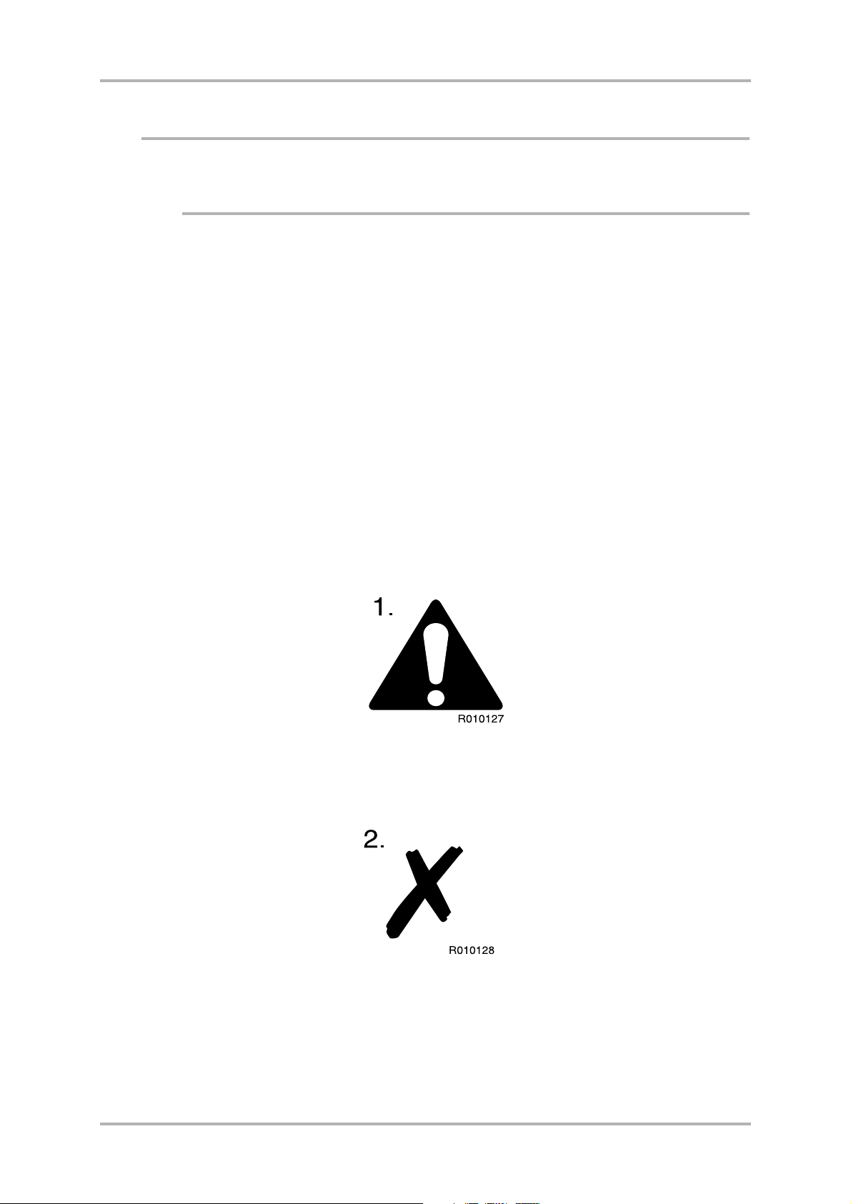
This symbol identifies important safety messages within this manual. Carefully read
the message that follows. Failure to understand and obey this safety warning could
result in injury to you or others, and could also cause damage to product. See
illustration 1.
This symbol identifies prohibited action or hazardous location. Failure to
understand and obey this safety warning could result in injury to you or others, and
could also cause damage to product. See illustration 2.
COPYRIGHT © 2019 SANDVIK MINING AND CONSTRUCTION OYPage 4 - Operation

RSS45R, RSS58R, RSS80R
R010265
This symbol identifies correct and recommended action. See illustration 3.
This symbol identifies environmental and recycling matter. See illustration 4.
ForewordRSS05R, RSS08R, RSS11R, RSS15R, RSS23R, RSS34R,
1.2 IMPORTANT SAFETY INFORMATION
Basic safety precautions are outlined in the "Safety" section of this manual and in
the instructions where hazards exist. These warnings are identified by a warning
symbol.
To use the product correctly, you must also be a competent operator of the carrier.
Do not use or install it if you cannot use the carrier. The product is a powerful tool.
Used without proper care, it can cause damage.
Do not rush when you are learning to use the product. Take your time and most
importantly, take it safely. Do not guess. If there is anything you do not understand,
ask your local dealer.
Improper operation, lubrication or maintenance of this product can be dangerous
and could result in injury.
Do not operate this product until you read and understand the instructions in this
manual.
Do not perform any lubrication and maintenance on this product until you read and
understand the instructions in this manual.
Operation - Page 5COPYRIGHT © 2019 SANDVIK MINING AND CONSTRUCTION OY

Foreword RSS05R, RSS08R, RSS11R, RSS15R, RSS23R, RSS34R,
RSS45R, RSS58R, RSS80R
1.3 WARRANTY
The customer is provided with a separate warranty sheet, where the export warranty
terms are explained. Check always that this warranty sheet is provided with the
product. If not, contact your local dealer immediately.
WARRANTY REGISTRATION CARD
A warranty registration card is filled out after the installation inspection by the
dealer and a copy of it is sent to the manufacturer. This card is very important
because no warranty claims are handled without it. Make sure that you get a copy
of it after the installation inspection and that it is correctly filled out.
INSTALLATION INSPECTION
An installation inspection must be carried out after the product has been installed on
the carrier. During the installation inspection, certain specifications (operating
pressure, oil flow, etc.) are checked so that they are within given limits. See
“Product specifications” on page 72.
1.4 SPARE PART ORDERS
When you need spare parts or some information concerning maintenance to your
product, please contact your local dealer. Quick deliveries are ensured by exact
orders.
Required information:
■ Name of customer, contact person
■ Order number (when available)
■ Delivery address
■ Mode of delivery (air mail, etc.)
■ Required delivery date
■ Invoicing address
■ Model and serial number of product
■ Name, number and required amount of spare parts
COPYRIGHT © 2019 SANDVIK MINING AND CONSTRUCTION OYPage 6 - Operation

RSS45R, RSS58R, RSS80R
Sandvik Mining and Construction Oy, Taivalkatu 8, 15170 LAHTI, FINLAND
Demolition tool
Manufactured by: MANTOVANIBENNE srl
n° 6, Via Righi - 41037 MIRANDOLA (Mo) ITALY
Serial number
Model
Manufactured
Weight (kg)
Min working
weight (kg)
Max cylinder pressure (bar)
Max rotation pressure (bar)
Max cylinder oil flow (l/min)
Max rotation oil flow (l/min)
2
3
4
5
6
7
8
9
10
1
11
S/N
MB010161
2. MACHINE NUMBERS
2.1 MODEL AND SERIAL NUMBER
The product serial number is stamped on the product body. The model and serial
number are also located on the product identification plate.
It is important to make correct reference to the serial number of the product when
making repairs or ordering spare parts. Identification of the serial number is the only
proper means of maintaining and identifying parts for a specific product.
See the following figure for the location of the serial number on your product
model.
Machine numbersRSS05R, RSS08R, RSS11R, RSS15R, RSS23R, RSS34R,
1
S/N
2
Serial number
3
Sandvik Mining and Construction Oy, Taivalkatu 8, 15170 LAHTI, FINLAND
Model
4
5
Manufactured
6
Demolition tool
Max cylinder pressure (bar)
Weight (kg)
Min working
weight (kg)
Manufactured by: MANTOVANIBENNE srl
n° 6, Via Righi - 41037 MIRANDOLA (Mo) ITALY
Max rotation pressure (bar)
Max cylinder oil flow (l/min)
Max rotation oil flow (l/min)
7
8
9
10
11
MB010160
Operation - Page 7COPYRIGHT © 2019 SANDVIK MINING AND CONSTRUCTION OY

Machine numbers RSS05R, RSS08R, RSS11R, RSS15R, RSS23R, RSS34R,
RSS45R, RSS58R, RSS80R
CONTENT OF THE PRODUCT IDENTIFICATION PLATE
1 Demolition tool
2 Serial number
3 Model
4 Weight (kg)
5 Min working weight (kg)
6 Manufactured
7 Max cylinder pressure (bar)
8 Max rotation pressure (bar)
9 Max cylinder oil flow (l/min)
10 Max rotation oil flow (l/min)
11 Manufactured by
COPYRIGHT © 2019 SANDVIK MINING AND CONSTRUCTION OYPage 8 - Operation

RSS45R, RSS58R, RSS80R
3. PRODUCT INTRODUCTION
3.1 OVERVIEW
The product is a hydraulically operated scrap shear. It can be used on any carrier
which meets the necessary hydraulic and mechanical installation requirements.
3.2 REMOVAL FROM PACKAGE
Remove all the steel belts from the package. Open the package and remove all
plastics covering the product. Recycle all package materials (steel, plastic, wood)
properly.
Check that the product is in good condition and that there is no visible damage.
Check that all ordered parts and accessories have been enclosed with the product.
Some options may be provided by your local dealer, such as installation kits,
including hoses and mounting bracket.
Product introductionRSS05R, RSS08R, RSS11R, RSS15R, RSS23R, RSS34R,
3.3 LIFTING INSTRUCTIONS
Use a hoist when lifting components which weigh 23 kg (51 lb) or more, to avoid
back injury. Make sure all chains, hooks, slings, etc., are in good condition and are
in the correct capacity. Make sure hooks are positioned correctly. Do not side load
the lifting eye during a lifting operation.
PROVIDED LIFTING POINTS
The lifting points located on the product frame are to be used solely to lift or handle
the product itself. The lifting capacity calculation is based on the product's working
weight, including an average sized mounting bracket.
Warning! To avoid falling objects, do not use the product to lift other products.
The lifting points located on the product frame are to be used solely to lift or
handle the product itself.
The maximum allowed total weight is shown on the product's identification plate
and specification page. See “Product specifications” on page 72. If the weight
exceeds the maximum allowed total weight shown on the identification plate and
specification page, you will have to use other lifting points/methods than originally
provided on the product.
Operation - Page 9COPYRIGHT © 2019 SANDVIK MINING AND CONSTRUCTION OY
Product introduction RSS05R, RSS08R, RSS11R, RSS15R, RSS23R, RSS34R,
G010014
RSS45R, RSS58R, RSS80R
The other threaded holes on the product are intended for handling single parts only.
You must not lift the entire assembly by using these threaded holes. For handling
the parts, see product workshop documentation for suitable lifting methods and
lifting adapters.
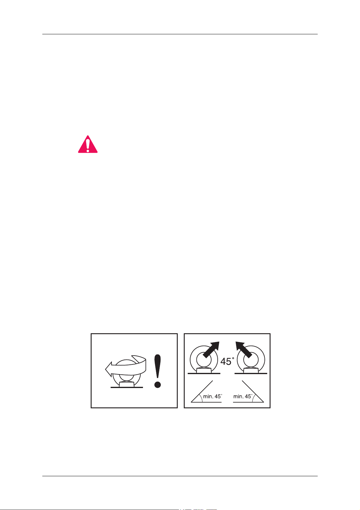
LIFTING EYE SCREWS
If lifting eye screws are used, lifting eye screws must be completely tightened. The
lifting eye can be loaded only if the screw is properly tightened to the frame.
Failure to properly tighten the screw before allowing load pressure on the
lifting eye may cause lifting eye to break and free fall of the product.
If you use mechanical tools for tightening, make sure not to overstrain the shank.
Before lifting, make sure that the rope and/or hook is stretched.
When two lifting points are used, the lifting capacity depends on the angle of the
lifting chains. The angle should not be less than 45°, as shown in the illustration.
When the lifting eye screws are tightened, both rings should be aligned.
The loading capacity calculation applies to temperatures between -10 °C (14 °F)
and 40 °C (104 °F).
Before reuse of lifting eye screws, make sure there are no surface flaws (for example
pits, voids, folds and seams, deformation of the ring, missing or broken threads,
rust, etc.).
The local, national safety standards for machines and lifting-tackles must always be
strictly observed.
Note: The lifting eye must always be removed from the product and replaced with
a screw before operation.
Lifting devices must safely carry the working weight of the product. See “Product
specifications” on page 72.
COPYRIGHT © 2019 SANDVIK MINING AND CONSTRUCTION OYPage 10 - Operation

RSS45R, RSS58R, RSS80R
Place a chain or sling as shown in the illustration to lift the product.
Product introductionRSS05R, RSS08R, RSS11R, RSS15R, RSS23R, RSS34R,
MB010013
Note: The lifting eye screws must always be removed from the product and replaced
with a screw before operation.
SAFETY INSTRUCTIONS FOR LIFTING
Below are some common safety instructions concerning lifting operations. In
addition to this, the local, national standards for machines and lifting-tackles must
always be strictly observed. Please note that the list below is not all inclusive, you
must always ensure the procedure you choose is safe for you and others.
■ Do not lift the load over people. No one must be under the hoisted load.
■ Do not lift people and never ride the hoisted load.
■ Keep people clear from the lift area.
■ Avoid side pull of the load. Make sure you take up the slack slowly. Start and
stop carefully.
■ Lift the load a few centimeters and verify it before proceeding. Make sure the
load is well balanced. Check for any loose items.
■ Never leave the suspended load unattended. Maintain load control at all times.
■ Never lift the load over the rated capacity (see the product's operating weight
from the specification page).
■ Inspect all lifting product before use. Do not use twisted or damaged lifting
product. Protect lifting product from sharp corners.
■ Obey all local safety instructions.
Operation - Page 11COPYRIGHT © 2019 SANDVIK MINING AND CONSTRUCTION OY

Product introduction RSS05R, RSS08R, RSS11R, RSS15R, RSS23R, RSS34R,
MB010020
A
C
E
B
D
D
D
F
RSS45R, RSS58R, RSS80R
3.4 MAIN PARTS
The main parts of the scrap shear are shown below.
A. Mounting bracket
B. Jaw
C. Thrust bearing
D. Cutting blades
E. Cylinder
F. Frame
COPYRIGHT © 2019 SANDVIK MINING AND CONSTRUCTION OYPage 12 - Operation

RSS45R, RSS58R, RSS80R
3.5 ENVIRONMENTAL PROTECTION AND RECYCLING POLICY
Rammer products support the recycling of materials to help customers achieve their
environmental objectives. During manufacturing all necessary precautions are
taken to make sure that no harm is done to the environment.
Every effort is made to foresee and minimize the risks that might be associated with
the operation and maintenance of Rammer products, and which could pose danger
to humans or the environment. We support customers in their efforts to consider the
environmental protection in their everyday work.
When working with a Rammer product please follow these guidelines:
■ Dispose of packaging materials properly. Wood and plastic can be burned or
recycled. Deliver the steel belts to metal recycling center.
■ Protect the environment from oil spills.
In case of hydraulic oil leaks, the product should be serviced immediately.
Follow the product's greasing instructions and avoid excessive greasing.
Product introductionRSS05R, RSS08R, RSS11R, RSS15R, RSS23R, RSS34R,
Be careful when handling, storing and transporting oils.
Dispose of empty oil or grease containers appropriately.
Consult local authorities for detailed instructions.
■ All metal parts of the product can be recycled by delivering them to an
authorized scrap metal collection facility.
■ Comply with local waste classification rules when disposing of used rubber or
plastic parts (wear plates, seals).
Consult with your local dealer for more information.
Operation - Page 13COPYRIGHT © 2019 SANDVIK MINING AND CONSTRUCTION OY

Safety RSS05R, RSS08R, RSS11R, RSS15R, RSS23R, RSS34R,
RSS45R, RSS58R, RSS80R
4. SAFETY
4.1 GENERAL SAFETY
All mechanical product can be hazardous if operated without due care or correct
maintenance. Most accidents involving machine operation and maintenance are
caused by failure to observe basic safety rules or precautions. An accident can often
be avoided by recognizing potentially hazardous situations before an accident
occurs.
Because it is impossible to anticipate every possible circumstance that might
involve a potential hazard, the warnings in this guide and on the product are not all
inclusive. If a procedure, tool, working method or operating technique not
specifically recommended by manufacturer is used, you must satisfy yourself that
it is safe for you and others. You should also ensure that the product will not be
damaged or made unsafe by the method of operation or maintenance procedures you
choose.
Safety is not just a matter of responding to the warnings. All the time you are
working with your product you must pay attention to what hazards there might be
and how to avoid them. Do not work with the product until you are sure that you can
control it. Do not start any job until you are sure that you and those around you will
be safe.
Warning! Read the following warning messages carefully. They tell you of
different hazards and how to avoid them. If proper precautions are not taken,
you or others could be seriously injured.
4.2 SAFETY INSTRUCTIONS
MANUALS
Study this manual before installing, operating or maintaining the product. If there is
anything you do not understand, ask your employer or your local dealer to explain
it. Keep this manual clean and in good condition.
The related safety label on the product and the text on the label are shown below.
"IGNORING INSTRUCTIONS HAZARD
Faulty handling practice could cause death or serious injury.
Read and follow the instructions in the operator's manual."
COPYRIGHT © 2019 SANDVIK MINING AND CONSTRUCTION OYPage 14 - Operation

RSS45R, RSS58R, RSS80R
R010348
IGNORING
INSTRUCTIONS HAZARD
Faulty handling practice could
cause death or severe injury.
Read and follow the instructions
in the operator’s manual.
WARNING
169410_ENG-3
SafetyRSS05R, RSS08R, RSS11R, RSS15R, RSS23R, RSS34R,
CARE AND ALERTNESS
All the time you are working with the product, take care and stay alert. Always be
alert for hazards. The possibility of a serious or even fatal accident is increased
when you are intoxicated.
CLOTHING
You can be injured if you do not wear proper clothing. Loose clothing can get
caught in the machinery. Wear protective clothing to suit the job.
Examples are: a safety helmet, safety shoes, safety glasses, well-fitting overalls,
ear-protectors and industrial gloves. Keep cuffs fastened. Do not wear a necktie or
scarf. Keep long hair restrained.
PRACTICE
You and others can be killed or injured if you perform unfamiliar operations without
practicing them first. Practice away from the job site, in a clear area.
Keep other people away. Do not perform new operations until you are sure you can
do them safely.
REGULATIONS AND LAWS
Obey all laws, work site and local regulations which affect you and your product.
Operation - Page 15COPYRIGHT © 2019 SANDVIK MINING AND CONSTRUCTION OY

Safety RSS05R, RSS08R, RSS11R, RSS15R, RSS23R, RSS34R,
R010214
RSS45R, RSS58R, RSS80R
COMMUNICATIONS
Bad communications can cause accidents. Keep people around you informed of
what you will be doing. If you will be working with other people, make sure they
understand any hand signals you will be using.
Worksites can be noisy. Do not rely on spoken commands.
WORKSITE
Worksites can be hazardous. Inspect the site before working on it.
Check for potholes, weak ground, hidden rocks, etc. Check for utilities (electric
cables, gas and water pipes, etc.). Mark the positions of cables and pipes.
Poor visibility can cause accidents and damage. Make sure that visibility and
lighting in the working area are adequate.
Worksites can be noisy. Wear ear protection to prevent personal injury.
BANKS AND TRENCHES
Banked material and trenches can collapse. Do not work too close to banks and
trenches where there is a danger of collapse.
SAFETY BARRIERS
Unguarded product in public places can be dangerous. Place barriers around
machinery to keep people away.
AIRBORNE POLLUTANTS
The related safety label on the product and the text on the label are shown below.
"DUST HAZARD
Breathing dust will cause death or severe injury.
Always wear approved respirator."
COPYRIGHT © 2019 SANDVIK MINING AND CONSTRUCTION OYPage 16 - Operation

RSS45R, RSS58R, RSS80R
R010349
DUST HAZARD
Breathing dust will cause death
or severe injury.
Always wear approved
respirator.
DANGER
169410_ENG-1
Airborne pollutants are microscopic particles, which will damage your health when
inhaled. Aiborne pollutants on construction sites can be for example silica dust, oil
fumes or diesel exhaust particles, visible or invisible. Especially in demolition sites,
there may be other dangerous substances, such as asbestos, lead paints or other
chemical substances.
SafetyRSS05R, RSS08R, RSS11R, RSS15R, RSS23R, RSS34R,
The effect of airborne pollutants may be immediate if the substance is poisonous.
The main danger with airborne pollutants comes from long term exposure, where
particles are inhaled but not removed from the lungs. The disease is called silicosis,
asbestosis or other, and will result in death or serious injury.
To protect yourself from airborne pollutants, always keep excavator doors and
windows closed during operation. Excavators with pressurized cabins should be
utilized in product operation. Proper maintenance of fresh air filters of the excavator
is essential. Where pressurized cabins are not available, proper respirators must be
utilized.
Stop working when bystanders are in the area of airborne pollutants and make sure
they have proper respirators. Respirators are as important for bystanders as hard
hats.Respirators for both operator and bystanders must be approved by the
respirator manufacturer for the application in question. It is essential that the
respirators protect from the tiny dust particles which cause silicosis and which may
cause other serious lung diseases. Do not use the product until you are sure the
respirators are working properly. This means each respirator must be checked to
make sure that it is clean, that its filter has been changed, and to otherwise make sure
the respirator will protect in the way it is meant to.
Always make sure dust has been cleaned off your boots and clothes when you leave
your shift. The smallest particles of dust are the most harmful. They may be so fine
that you cannot see them. Remember, you MUST protect yourself and bystanders
from the danger of breathing or inhaling dust.
Always follow local laws and regulations for airborne pollutants in the working
environment.
Operation - Page 17COPYRIGHT © 2019 SANDVIK MINING AND CONSTRUCTION OY
Safety RSS05R, RSS08R, RSS11R, RSS15R, RSS23R, RSS34R,
R010350
FLYING OBJECTS HAZARD
Fragments fly up to 40 m (130 ft)
and could cause death or severe
injury.
Stop operation when a
person enters hazard zone.
Wear approved personal
protective equipment.
WARNING
169410_ENG-2
RSS45R, RSS58R, RSS80R
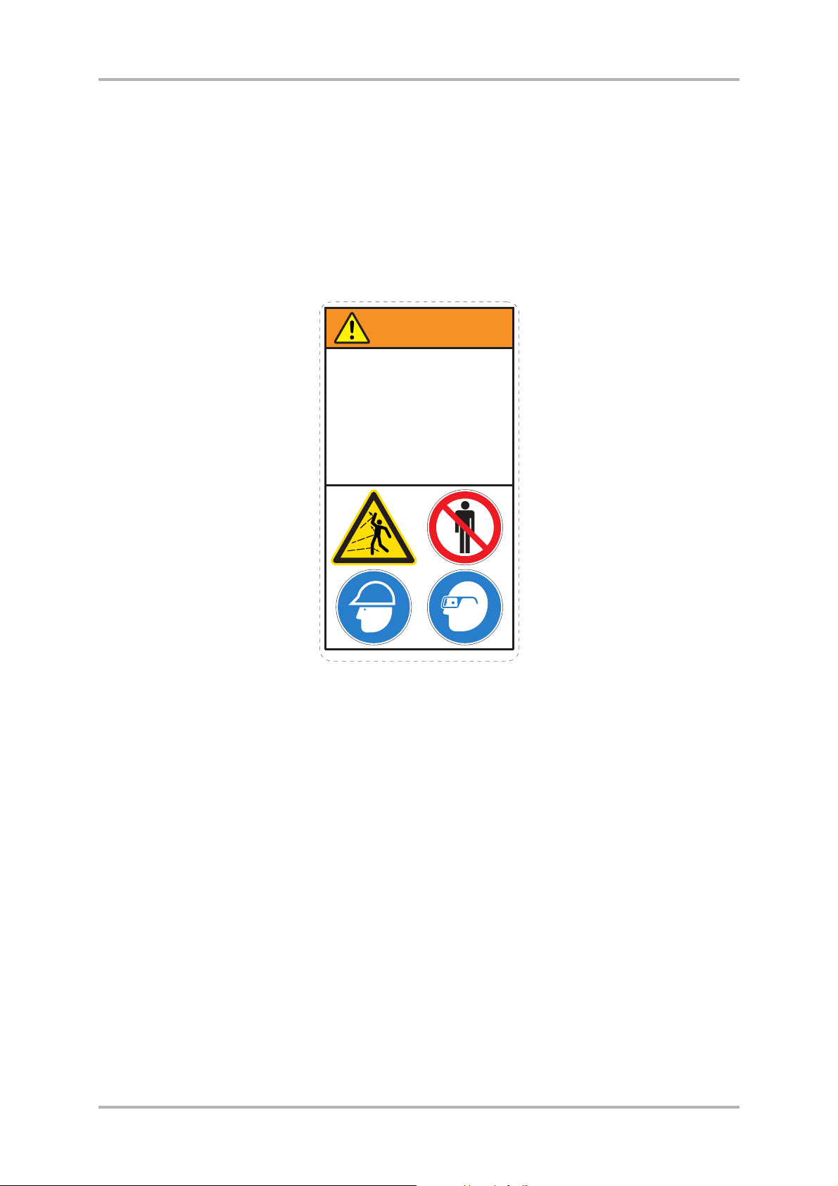
FLYING DEMOLITION DEBRIS
The safety label on the product is shown below:
"FLYING OBJECTS HAZARD
Fragments fly up to 40 m (130 ft) and could cause death or serious injury.
Stop operation when a person enters hazard zone.
Wear approved personal protective product."
Protect yourself and your surroundings from flying debris. Do not operate the
product or carrier with people around it.
The European standard EN 474-1 on safety of earth-moving machinery requires that
adequate operator's protection, such as bullet proof glass, mesh guard or an
equivalent protection is used.
Keep the cabin windows and doors closed during operation. Window bars are
recommended to protect the windows from flying debris.
CRUSHING HAZARD
The safety label on the product is shown below:
"CRUSHING HAZARD
Contact with moving parts or material could cause death or severe injury.
Keep yourself and bystanders out of hazard zone."
COPYRIGHT © 2019 SANDVIK MINING AND CONSTRUCTION OYPage 18 - Operation

RSS45R, RSS58R, RSS80R
G010031
SafetyRSS05R, RSS08R, RSS11R, RSS15R, RSS23R, RSS34R,
COLLAPSING CONCRETE FRAMES
Protect yourself and your surroundings from collapsing concrete frames. Do not
operate the product or carrier with people around it.
PRODUCT LIMITS
Operating the product beyond its design limits can cause damage. It can also be
dangerous. See “Product specifications” on page 72.
Do not try to upgrade the product's performance by unapproved modifications.
HYDRAULIC FLUID
Fine jets of hydraulic fluid at high pressure can penetrate the skin. Do not use your
fingers to check for hydraulic fluid leaks. Do not put your face close to suspected
leaks. Hold a piece of cardboard close to suspected leaks and then inspect the
cardboard for signs of hydraulic fluid. If hydraulic fluid penetrates your skin, seek
medical help immediately.
Hot hydraulic fluid can cause severe injuries.
HYDRAULIC HOSES AND FITTINGS
Ensure all hydraulic components will withstand maximum pressure and mechanical
stresses caused by operation of the product. Consult your local dealer for
instructions.
Operation - Page 19COPYRIGHT © 2019 SANDVIK MINING AND CONSTRUCTION OY

Safety RSS05R, RSS08R, RSS11R, RSS15R, RSS23R, RSS34R,
RSS45R, RSS58R, RSS80R
FIRE HAZARD
Most hydraulic fluids are flammable and might ignite when contacting hot surface.
Avoid spilling hydraulic fluid to hot surfaces.
Working with the product on certain materials can cause sparks and hot splinters to
get loose. These can ignite flammable materials around working area.
Ensure that adequate extinguisher is available.
HYDRAULIC PRESSURE
Hydraulic fluid at system pressure can injure you. Before disconnecting or
connecting hydraulic hoses, stop the carrier engine and operate the controls to
release pressure trapped in the hoses. During operation, keep people away from the
hydraulic hoses.
There might be pressurized oil trapped inside the product even if it is disconnected
from the carrier. Be aware of possible unexpected jaw movements while
maintaining product.
LIFTING EQUIPMENT
You can be injured if you use faulty lifting equipment. Make sure that lifting
equipment is in good condition. Make sure that the lifting tackle complies with all
local regulations and is suitable for the job. Make sure that the lifting equipment is
strong enough for the job and you know how to use it.
Do not use this product or any of its parts for lifting. Contact your carrier dealer to
find out how to lift with your carrier.
SPARE PARTS
Use only genuine spare parts. Use only genuine cutting blades with scrap shears.
The use of other spare part or cutting blade brands may damage the product.
PRODUCT CONDITION
Defective product can injure you or others. Do not operate product which is
defective or has missing parts.
Make sure the maintenance procedures in this manual are completed before using
the product.
REPAIRS AND MAINTENANCE
Do not try to do repairs or any other maintenance work you do not understand.
COPYRIGHT © 2019 SANDVIK MINING AND CONSTRUCTION OYPage 20 - Operation

RSS45R, RSS58R, RSS80R
MODIFICATIONS AND WELDING
Non-approved modifications can cause injury and damage. Contact your local
dealer for advice before modifying the product. Before welding on the product
while it is installed on the carrier, consult your carrier dealer for precautions in
welding.
METAL SPLINTERS
You can be injured by flying splinters when driving metal pins in and out. Use softfaced hammer or drifts to remove and fit metal pins, such as pivot pins. Always wear
safety glasses.
LABELS ON THE PRODUCT
Safety labels communicate the following four things:
■ The severity level of the risk (that is signal word "DANGER" or
"WARNING").
SafetyRSS05R, RSS08R, RSS11R, RSS15R, RSS23R, RSS34R,
■ The nature of the hazard (such as high pressure, dust, etc.).
■ The consequence of interaction with the hazard.
■ How to avoid the hazard.
You must ALWAYS follow the instructions in the safety messages, the messages
in the product safety labels and the instructions set forth in the manuals to avoid
death or severe injury!
Keep the safety labels clean and visible at all times. Check the condition of safety
labels daily. Safety labels and instructions which have disappeared, been damaged,
painted over, come loose, or do not meet the legibility requirements for safe viewing
distance must be replaced before operating the product.
If a safety label is attached to a part that is replaced, install a new safety label on the
replacement part. If this manual is available in your language, then the safety labels
should be available in the same language.
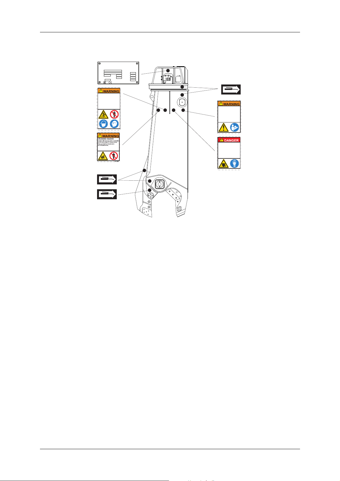
There are several specific safety labels on this product. Please become familiarized
with all safety labels. The location of the safety labels is shown in the illustration
below.
When you clean the safety labels, use a cloth, water and soap. Do not use solvent,
gasoline or other harsh chemicals to clean the safety labels.
Solvents, gasoline or harsh chemicals could loosen the adhesive that secures the
safety labels. Loose adhesive will allow the safety label to fall.
Operation - Page 21COPYRIGHT © 2019 SANDVIK MINING AND CONSTRUCTION OY

Safety RSS05R, RSS08R, RSS11R, RSS15R, RSS23R, RSS34R,
DUST HAZARD
Breathing dust will cause death
or severe injury.
Always wear approved
respirator.
169410_ENG-1
FLYING OBJECTS HAZARD
Fragments fly up to 40 m (130 ft)
and could cause death or severe
injury.
Stop operation when a
person enters hazard zone.
Wear approved personal
protective equipment.
169410_ENG-2
IGNORING
INSTRUCTIONS HAZARD
Faulty handling practice could
cause death or severe injury.
Read and follow the instructions
in the operator's manual.
169410_ENG-3
MB010110
Sandvik Mining and Construction Oy, Taivalkatu 8, 15170 LAHTI, FINLAND
Demolition tool
Manufactured by: MANTOVANIBENNE srl
n° 6, Via Righi - 41037 MIRANDOLA (Mo) ITALY
Serial number
Model
Manufactured
Weight (kg)
Min working
weight (kg)
Max cylinder pressure (bar)
Max rotation pressure (bar)
Max cylinder oil flow (l/min)
Max rotation oil flow (l/min)
RSS45R, RSS58R, RSS80R
RSS08R
Demolition tool
Sandvik Mining and Construction Oy, Taivalkatu 8, 15170 LAHTI, FINLAND
Serial number
Model
Manufactured
Max cylinder pressure (bar)
Max rotation pressure (bar)
Weight (kg)
Min working
Max cylinder oil flow (l/min)
weight (kg)
Max rotation oil flow (l/min)
Manufactured by: MANTOVANIBENNE srl
n° 6, Via Righi - 41037 MIRANDOLA (Mo) ITALY
DUST HAZARD
Breathing dust will cause death
or severe injury.
Always wear approved
respirator.
RSS15R
169410_ENG-1
IGNORING
INSTRUCTIONS HAZARD
Faulty handling practice could
cause death or severe injury.
Read and follow the instructions
in the operator's manual.
169410_ENG-3
FLYING OBJECTS HAZARD
Fragments fly up to 40 m (130 ft)
and could cause death or severe
injury.
Stop operation when a
person enters hazard zone.
Wear approved personal
protective equipment.
169410_ENG-2
MB010108
COPYRIGHT © 2019 SANDVIK MINING AND CONSTRUCTION OYPage 22 - Operation

RSS45R, RSS58R, RSS80R
IGNORING
INSTRUCTIONS HAZARD
Faulty handling practice could
cause death or severe injury.
Read and follow the instructions
in the operator's manual.
169410_ENG-3
DUST HAZARD
Breathing dust will cause death
or severe injury.
Always wear approved
respirator.
169410_ENG-1
FLYING OBJECTS HAZARD
Fragments fly up to 40 m (130 ft)
and could cause death or severe
injury.
Stop operation when a
person enters hazard zone.
Wear approved personal
protective equipment.
169410_ENG-2
MB010109
Sandvik Mining and Construction Oy, Taivalkatu 8, 15170 LAHTI, FINLAND
Demolition tool
Manufactured by: MANTOVANIBENNE srl
n° 6, Via Righi - 41037 MIRANDOLA (Mo) ITALY
Serial number
Model
Manufactured
Weight (kg)
Min working
weight (kg)
Max cylinder pressure (bar)
Max rotation pressure (bar)
Max cylinder oil flow (l/min)
Max rotation oil flow (l/min)
MB010133
IGNORING
INSTRUCTIONS HAZARD
Faulty handling practice could
cause death or severe injury.
Read and follow the instructions
in the operator's manual.
169410_ENG-3
DUST HAZARD
Breathing dust will cause death
or severe injury.
Always wear approved
respirator.
169410_ENG-1
FLYING OBJECTS HAZARD
Fragments fly up to 40 m (130 ft)
and could cause death or severe
injury.
Stop operation when a
person enters hazard zone.
Wear approved personal
protective equipment.
169410_ENG-2
Sandvik Mining and Construction Oy, Taivalkatu 8, 15170 LAHTI, FINLAND
Demolition tool
Manufactured by: MANTOVANIBENNE srl
n° 6, Via Righi - 41037 MIRANDOLA (Mo) ITALY
Serial number
Model
Manufactured
Weight (kg)
Min working
weight (kg)
Max cylinder pressure (bar)
Max rotation pressure (bar)
Max cylinder oil flow (l/min)
Max rotation oil flow (l/min)
RSS23R
SafetyRSS05R, RSS08R, RSS11R, RSS15R, RSS23R, RSS34R,
RSS34R
Operation - Page 23COPYRIGHT © 2019 SANDVIK MINING AND CONSTRUCTION OY

Safety RSS05R, RSS08R, RSS11R, RSS15R, RSS23R, RSS34R,
MB010131
IGNORING
INSTRUCTIONS HAZARD
Faulty handling practice could
cause death or severe injury.
Read and follow the instructions
in the operator's manual.
169410_ENG-3
DUST HAZARD
Breathing dust will cause death
or severe injury.
Always wear approved
respirator.
169410_ENG-1
FLYING OBJECTS HAZARD
Fragments fly up to 40 m (130 ft)
and could cause death or severe
injury.
Stop operation when a
person enters hazard zone.
Wear approved personal
protective equipment.
169410_ENG-2
Sandvik Mining and Construction Oy, Taivalkatu 8, 15170 LAHTI, FINLAND
Demolition tool
Manufactured by: MANTOVANIBENNE srl
n° 6, Via Righi - 41037 MIRANDOLA (Mo) ITALY
Serial number
Model
Manufactured
Weight (kg)
Min working
weight (kg)
Max cylinder pressure (bar)
Max rotation pressure (bar)
Max cylinder oil flow (l/min)
Max rotation oil flow (l/min)
RSS45R, RSS58R, RSS80R
RSS45R
Demolition tool
Sandvik Mining and Construction Oy, Taivalkatu 8, 15170 LAHTI, FINLAND
Serial number
Model
Manufactured
Max cylinder pressure (bar)
Weight (kg)
Max rotation pressure (bar)
Min working
Max cylinder oil flow (l/min)
weight (kg)
Max rotation oil flow (l/min)
Manufactured by: MANTOVANIBENNE srl
n° 6, Via Righi - 41037 MIRANDOLA (Mo) ITALY
DUST HAZARD
Breathing dust will cause death
or severe injury.
Always wear approved
respirator.
169410_ENG-1
RSS58R
IGNORING
INSTRUCTIONS HAZARD
Faulty handling practice could
cause death or severe injury.
Read and follow the instructions
in the operator's manual.
169410_ENG-3
FLYING OBJECTS HAZARD
Fragments fly up to 40 m (130 ft)
and could cause death or severe
injury.
Stop operation when a
person enters hazard zone.
Wear approved personal
protective equipment.
169410_ENG-2
MB010130
COPYRIGHT © 2019 SANDVIK MINING AND CONSTRUCTION OYPage 24 - Operation
RSS45R, RSS58R, RSS80R
RSS05R, RSS11R, RSS80R
Sandvik Mining and Construction Oy, Taivalkatu 8, 15170 LAHTI, FINLAND
Serial number
Model
Weight (kg)
Min working
weight (kg)
Manufactured
Manufactured by: MANTOVANIBENNE srl
n° 6, Via Righi - 41037 MIRANDOLA (Mo) ITALY
FLYING OBJECTS HAZARD
Fragments fly up to 40 m (130 ft)
and could cause death or severe
injury.
Stop operation when a
person enters hazard zone.
Wear approved personal
protective equipment.
Demolition tool
Max cylinder pressure (bar)
Max rotation pressure (bar)
Max cylinder oil flow (l/min)
Max rotation oil flow (l/min)
IGNORING
INSTRUCTIONS HAZARD
Faulty handling practice could
cause death or severe injury.
Read and follow the instructions
in the operator's manual.
SafetyRSS05R, RSS08R, RSS11R, RSS15R, RSS23R, RSS34R,
169410_ENG-2
DUST HAZARD
Breathing dust will cause death
or severe injury.
Always wear approved
respirator.
MB010024
169410_ENG-3
169410_ENG-1
Operation - Page 25COPYRIGHT © 2019 SANDVIK MINING AND CONSTRUCTION OY

Operation RSS05R, RSS08R, RSS11R, RSS15R, RSS23R, RSS34R,
RSS45R, RSS58R, RSS80R
5. OPERATION
5.1 OPERATING INSTRUCTIONS
RECOMMENDED USE
The scrap shear is designed for use in cutting steel sections and scraps with
maximum efficiency to prepare them for the furnace or for transport. For more
information, contact your local dealer.
OPERATING CONDITIONS
Principles of installation
Almost all carriers meeting mechanical and hydraulic requirements can be used to
operate products. See “Product specifications” on page 72. The product is installed
on the carrier much in the same manner as installing a bucket or other attachment.
A flange-mounted products requires also a separate mounting bracket.
The products is connected to a carrier's hydraulic circuit with an installation kit. If
the carrier is already fitted with an installation kit, the installation requires only
suitable hoses and fittings. For product installation, secondary relief valves in the
bucket cylinder circuit and the carrier auxiliary circuit are needed. If the carrier does
not have a suitable kit to run attachments, one must be built. This may require a
more complex installation, including new piping and additional valves such as a
flow control valve or pressure relief valve.
Suitable kits can be ordered from the manufacturer or their local dealers, carrier
manufacturers and their dealers, or third party suppliers.
Note: In models equipped with a system to prevent rotation of the product,
remember to unlock the system before starting operation. See “Mounting and
dismounting the product” on page 34.
Hydraulic oil
In general, the hydraulic oil originally intended for the carrier can be used with this
product.
Operating temperature
The operating temperature is -20 °C (-4 °F) to 80 °C (176 °F). If you must work in
a temperature lower than -20 °C (-4 °F), the product must be preheated before any
operation can begin. Start the operation with low hydraulic flow.
Note: The temperature of the hydraulic oil must be monitored. Ensure that oil grade
and monitored oil temperature together guarantee correct oil viscosity.
COPYRIGHT © 2019 SANDVIK MINING AND CONSTRUCTION OYPage 26 - Operation

RSS45R, RSS58R, RSS80R
PRINCIPLES OF OPERATION
The operation of the product is based on a static force produced by the hydraulic
cylinder of the product. To increase the product's working life, pay particular
attention to correct working methods.
Cutting is performed with cutting blades at the rear of the jaws. The cutting blades
can be reversed.
JAWS, TEETH AND CUTTING BLADES
Jaws
The jaws are operated by the hydraulic cylinder. One jaw is fixed and the other,
equipped with breaking teeth, is moving. Crushing is performed using the crushing
teeth of the jaws.
Cutting blades
The cutting blades are fastened with screws. You can turn them to use unused
cutting edges or replace them with new cutting blades. See “Turning and changing
cutting blades” on page 53.
OperationRSS05R, RSS08R, RSS11R, RSS15R, RSS23R, RSS34R,
Operation - Page 27COPYRIGHT © 2019 SANDVIK MINING AND CONSTRUCTION OY
Operation RSS05R, RSS08R, RSS11R, RSS15R, RSS23R, RSS34R,
MB010036
RSS45R, RSS58R, RSS80R
5.2 DAILY OPERATION
Warning! Protect yourself and your surroundings from flying debris and
collapsing concrete frames. Do not operate the product or carrier with people
around it.
The product, as a standard assembly, must not be used under water. It must be
adapted for underwater applications. Contact your local dealer for more
information on underwater use.
After operating the product under water or in environments close to the sea,
carefully wash the product. Subsequently disassemble the hinges and carefully
clean the pins and bushings to remove all traces of oxidation. Lastly, grease the
disassembled parts.
MB010035
In models equipped with a rotation prevention system, remember to unlock the
system before starting operation.
Remove the cotter pin and take out the locking pin.
COPYRIGHT © 2019 SANDVIK MINING AND CONSTRUCTION OYPage 28 - Operation

RSS45R, RSS58R, RSS80R
MB010071
MB010070
■ Prepare the carrier for normal excavation work. Move the carrier to the required
position. Set the drive to neutral.
■ Set the engine speed to the recommended engine RPM.
■ NOTICE! Carefully operate the carrier controls to place the product and boom
into the working position. Quick and careless boom movements can result in
damage to the product.
OperationRSS05R, RSS08R, RSS11R, RSS15R, RSS23R, RSS34R,
■ Use a safety screen to protect the operator from flying debris. Keep the cabin
windows and doors closed during operation.
MB010072
■ Do not move or cut material over people, the excavator cab, or other operating
machines.
Operation - Page 29COPYRIGHT © 2019 SANDVIK MINING AND CONSTRUCTION OY

Operation RSS05R, RSS08R, RSS11R, RSS15R, RSS23R, RSS34R,
MB010069
MB010073
RSS45R, RSS58R, RSS80R
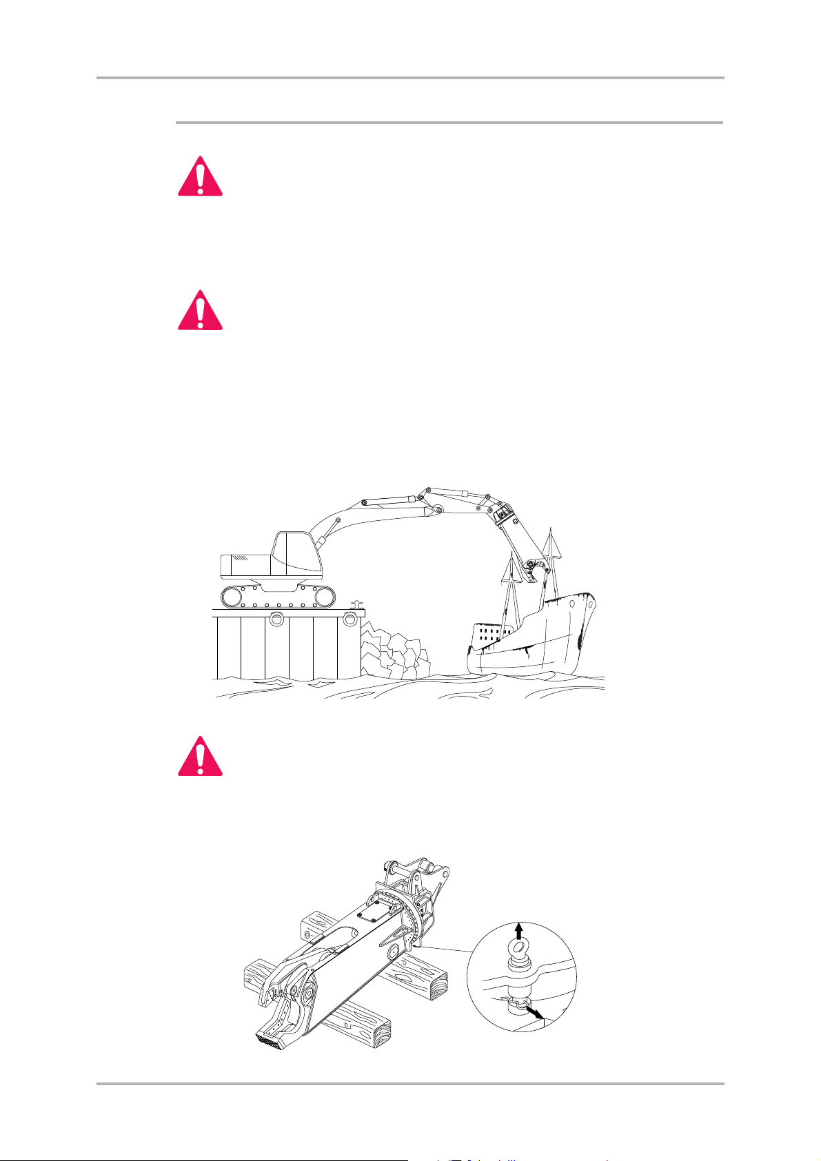
■ To avoid a dangerous fall, ensure that the structure your carrier is on is strong
enough to support it.
■ Do not operate excavator hydraulic cylinders when the jaws are closed.
Bending the object up and down when the jaws are pressed on it may cause
excessive wearing of teeth and cutting blades.
COPYRIGHT © 2019 SANDVIK MINING AND CONSTRUCTION OYPage 30 - Operation

RSS45R, RSS58R, RSS80R
MB010074
■ Do not use the product for lifting. Lifting eyes on the product are for storage and
maintenance purposes only.
OperationRSS05R, RSS08R, RSS11R, RSS15R, RSS23R, RSS34R,
■ When cutting horizontal steel frames, concentrate the shearing action at the
proper working angle. Cut through at one point on the frame. Cut partially
through at another point. Then, bend the framework down with the product and
make the final cut.
Operation - Page 31COPYRIGHT © 2019 SANDVIK MINING AND CONSTRUCTION OY

Operation RSS05R, RSS08R, RSS11R, RSS15R, RSS23R, RSS34R,
RSS45R, RSS58R, RSS80R
■ Place steel frames properly between the cutting blades, as shown in the
illustration. Note: If the cutting object does not fit into the product mouth, first
press it between the jaws to flatten it and then perform the final cutting with the
cutting blades.
■ Do not use the product to move the excavator.
MB010078
■ When operating the product, make sure that it does not make contact with the
carrier boom or hydraulic lines.
MB010079
COPYRIGHT © 2019 SANDVIK MINING AND CONSTRUCTION OYPage 32 - Operation
RSS45R, RSS58R, RSS80R
MB010076
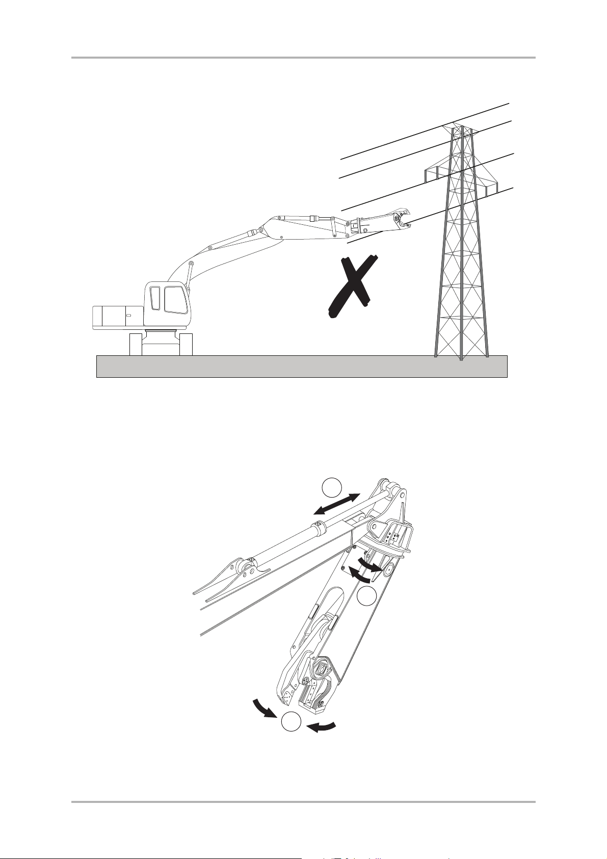
■ Stay more than 10 meters (33 feet) away from live, overhead electric cables
with any part of the machine.
OperationRSS05R, RSS08R, RSS11R, RSS15R, RSS23R, RSS34R,
■ When carrying out demolition work, position the product by means of hydraulic
rotation (2), in such a way as to ensure that always have the correct angle of
penetration (1). Use just the force of the cylinder for demolishing, without
trying to tear at the material with the excavator arm (3). If necessary, re-position
the product.
3
2
1
MB010080
Operation - Page 33COPYRIGHT © 2019 SANDVIK MINING AND CONSTRUCTION OY

Operation RSS05R, RSS08R, RSS11R, RSS15R, RSS23R, RSS34R,
MB010092
RSS45R, RSS58R, RSS80R
■ The bearings must be well greased during operation. Make regular inspections
during operation. If no grease is visible, the bearings require more frequent
greasing. If bearings are covered with excessive grease, they require less
frequent greasing.
5.3 MOUNTING AND DISMOUNTING THE PRODUCT
REMOVAL FROM CARRIER
Warning! The product must be secured from falling over when disconnecting
it from the carrier. Only use a skilled operator to position the carrier for the
removal!
Warning! Hydraulic pressure inside the product must always be released
before opening hose connections!
Warning! Hot hydraulic fluid can cause severe injuries!
Warning! The thrust bearing must be locked to prevent the product from
rotating during maintenance or transportation.
1. Position the product horizontally on the floor.
2. Stop the carrier engine. Operate the boom and product controls to release
pressure trapped inside hoses.
COPYRIGHT © 2019 SANDVIK MINING AND CONSTRUCTION OYPage 34 - Operation

RSS45R, RSS58R, RSS80R
MB010082
3. Close the product shut-off valve. If quick couplers are used, disconnection
automatically closes product lines. If the line includes ball valves, make sure
that they are closed.
4. Disconnect the hoses. Protect the environment from oil spills. Plug the hoses.
5. Remove the mounting bracket pins and other parts.
OperationRSS05R, RSS08R, RSS11R, RSS15R, RSS23R, RSS34R,
MB010091
Operation - Page 35COPYRIGHT © 2019 SANDVIK MINING AND CONSTRUCTION OY

Operation RSS05R, RSS08R, RSS11R, RSS15R, RSS23R, RSS34R,
RSS45R, RSS58R, RSS80R
6. Install the locking pins and cotter pins.
MB010087
7. Move the carrier aside, if needed.
INSTALLATION ON THE CARRIER
Warning! The residual air in the hoses must always be removed before
operation!
1. Remove the cotter pins and take out the locking pins.
MB010086
COPYRIGHT © 2019 SANDVIK MINING AND CONSTRUCTION OYPage 36 - Operation

RSS45R, RSS58R, RSS80R
2. Install the product in the same manner as mounting a bucket. Install bucket pins.
OperationRSS05R, RSS08R, RSS11R, RSS15R, RSS23R, RSS34R,
MB010093
3. Connect the hoses. An installation inspection must be carried out after the
product has been mounted on the carrier. During installation inspection, certain
specifications (operating pressure, oil flow, etc.) are checked so that they are
within given limits. See “Product specifications” on page 72.
4. Open the ball valves.
5. Remove the air from the hoses by carefully operating the crusher cylinder.
Open and close the empty jaws several times.
Note:
■ If the lines going to the opening and closing connection have two different
pressure values, connect the line with the highest pressure (which should not
exceed the max. value) to the connection fitting jaw closing and the lower
pressure line to the connection fitting jaw opening, in order to have the
maximum clamping force.
■ Remove the cap from the fitting of the hydraulic hoses connecting the excavator
and the crusher.
■ Make sure that the hose fittings are perfectly clean and dust-free, and attach
them to the machine by tightening the screws or the fittings.
Operation - Page 37COPYRIGHT © 2019 SANDVIK MINING AND CONSTRUCTION OY

Operation RSS05R, RSS08R, RSS11R, RSS15R, RSS23R, RSS34R,
MB010096
RSS45R, RSS58R, RSS80R
Note:
■ The hydraulic rotation motor can operate with the drainage outlet plugged if,
during activation, the back-pressure on the drainage branch during operation is
not greater than 15 bar (218 psi).
■ At first installation, check the backpressure value on the return branch of the
rotation system, activating the hydraulic rotation in both directions.
■ If the measured back pressure is greater than 15 bar (218 psi), connect a
drainage line that connects the drainage attachment of the motor to the tank.
■ The drainage attachment of the motor, normally plugged, is located on the
bottom of the motor (see illustration).
1&4” GAS
MB010101
5.4 MOVEMENT
The transportation and parking positions are shown below. When moving the
carrier, ensure that the product is not too close to the carrier.
COPYRIGHT © 2019 SANDVIK MINING AND CONSTRUCTION OYPage 38 - Operation

RSS45R, RSS58R, RSS80R
5.5 SPECIAL CONDITIONS OF USE
The product may require modifications, special operating techniques, increased
maintenance or special wear items if it is used in conditions that differ from normal
breaking or demolition work. Special conditions of use are:
■ Underwater operations
■ Operations in extremely low or high temperatures
■ Use of special hydraulic fluids
■ Operations with special carrier
■ Other special conditions
In case of special conditions of use, contact your local dealer for instructions.
OperationRSS05R, RSS08R, RSS11R, RSS15R, RSS23R, RSS34R,
The product as a standard assembly, must not be used under water. Contact
your local dealer for more information on underwater use.
5.6 STORAGE
LONG TERM STORAGE
Observe the following points when the product is stored. This way, the vital parts
of the product are protected from rust and the product is ready to be used whenever
necessary.
1. Make sure your storage area is dry.
2. To avoid damaging the cylinder rod, operate the cylinder to the shortest position
by leaving the jaws open.
Operation - Page 39COPYRIGHT © 2019 SANDVIK MINING AND CONSTRUCTION OY

Operation RSS05R, RSS08R, RSS11R, RSS15R, RSS23R, RSS34R,
MB010099
RSS45R, RSS58R, RSS80R
3. Insert blocks under the product to keep it off the ground. If the product is stored
outside, cover it to prevent rusting.
4. Apply grease to all product parts. Protect the mounting bracket, pin holes,
cutting blades and pivot ends with an anticorrosive agent.
5. Seal connections with clean plugs to prevent oil leakage and dirt from getting
into the couplings.
6. Make sure the product cannot fall over.
COPYRIGHT © 2019 SANDVIK MINING AND CONSTRUCTION OYPage 40 - Operation

RSS05R, RSS08R, RSS11R, RSS15R, RSS23R, RSS34R,
RSS45R, RSS58R, RSS80R
LUBRICATION
Lubrication - Page 41COPYRIGHT © 2019 SANDVIK MINING AND CONSTRUCTION OY

Greasing RSS05R, RSS08R, RSS11R, RSS15R, RSS23R, RSS34R,
RSS45R, RSS58R, RSS80R
1. GREASING
1.1 RECOMMENDED GREASES
Item Recommended greases Greasing interval
Pins and bushings every 8 hours
Thrust bearing every 40...80 hours
Additives: molybdenum disulfide
Minimum working temperature below
lowest ambient temperature
Penetration 0 ... 2 (NLGI)
No reaction with hydraulic oils
Water resistant
Good adhesion with steel
1.2 GREASING POINTS
Follow the product's greasing instructions and avoid excessive greasing.
Dispose of empty grease containers appropriately.
The greasing points of the product are marked with the following sticker.
COPYRIGHT © 2019 SANDVIK MINING AND CONSTRUCTION OYPage 42 - Lubrication

RSS45R, RSS58R, RSS80R
MB020003
The greasing points of the product are shown below.
GreasingRSS05R, RSS08R, RSS11R, RSS15R, RSS23R, RSS34R,
Lubrication - Page 43COPYRIGHT © 2019 SANDVIK MINING AND CONSTRUCTION OY

Carrier hydraulic oil RSS05R, RSS08R, RSS11R, RSS15R, RSS23R, RSS34R,
RSS45R, RSS58R, RSS80R
2. CARRIER HYDRAULIC OIL
2.1 REQUIREMENTS FOR HYDRAULIC OIL
GENERAL REQUIREMENTS
In general, the hydraulic oil originally intended for the carrier can be used with this
product. However, since working with the product heats the oil more than with the
usual excavation work, the temperature of the oil must be monitored.
If the temperature of the hydraulic oil exceeds 80 °C (176 °F), an auxiliary oil cooler
is needed. The oil viscosity must be between 1000-20 cSt while the product is being
used.
When the product is used continuously, the temperature of the hydraulic oil
normalizes at a certain level depending on conditions and on the carrier. The
temperature in the tank must not exceed the maximum allowed.
The product must not be started if the ambient temperature is below freezing and
the oil is very thick. The machine must be moved to bring the oil temperature above
0 °C (32 °F) before working can start (viscosity 1000 cSt or 131 °E).
COPYRIGHT © 2019 SANDVIK MINING AND CONSTRUCTION OYPage 44 - Lubrication
RSS45R, RSS58R, RSS80R
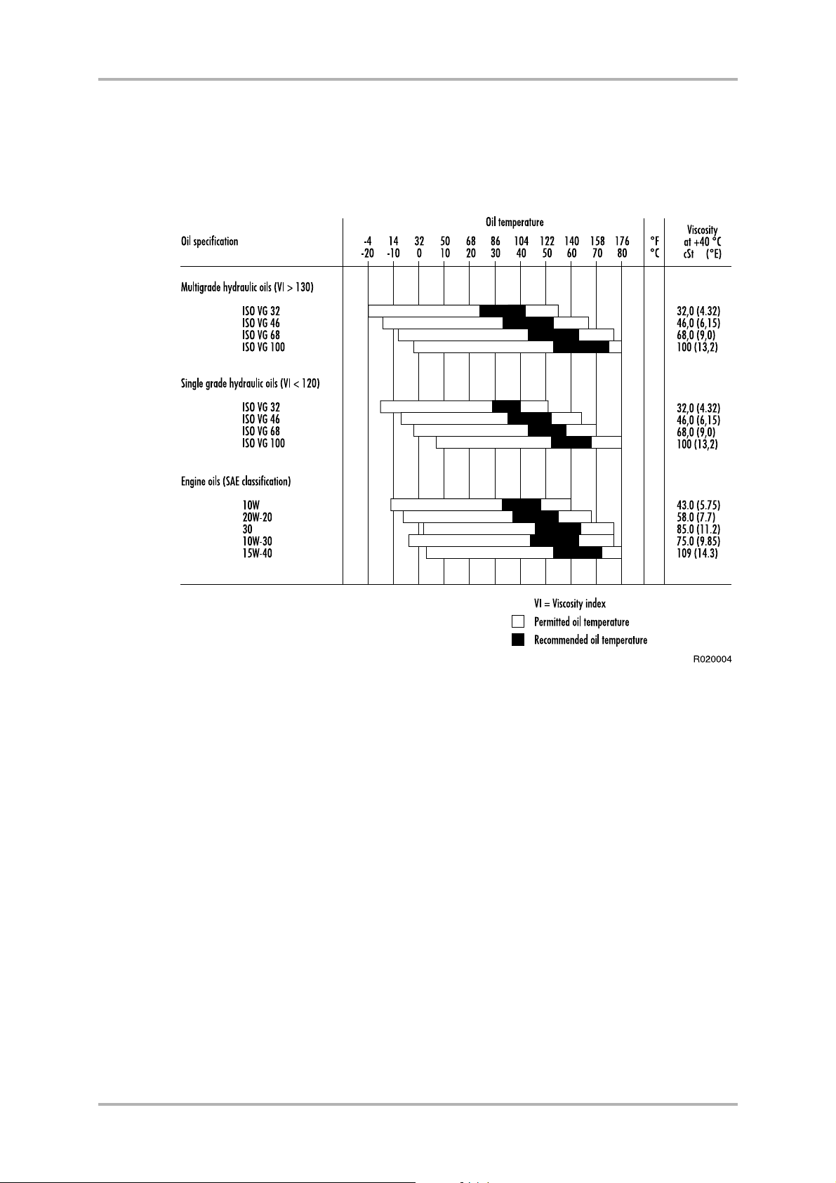
OIL SPECIFICATIONS
The table below shows hydraulic oils recommended for product use. The most
suitable oil is selected in such a way that the temperature of the hydraulic oil in
continuous use is in the ideal area on the chart and the hydraulic system is used to
best advantage.
Carrier hydraulic oilRSS05R, RSS08R, RSS11R, RSS15R, RSS23R, RSS34R,
Problems due to incorrect hydraulic oil viscosity in the product:
Oil too thick
■ Difficult start up
■ Stiff operation
■ Danger of cavitation
■ Sticky valves
■ Filter bypass opens, impurities in the oil are not removed
Oil too thin
■ Efficiency losses (internal leaks)
■ Damage to gaskets and seals, leaks
■ Accelerated wearing of parts, because of decreased lubrication efficiency
■ Danger of cavitation
Lubrication - Page 45COPYRIGHT © 2019 SANDVIK MINING AND CONSTRUCTION OY

Carrier hydraulic oil RSS05R, RSS08R, RSS11R, RSS15R, RSS23R, RSS34R,
RSS45R, RSS58R, RSS80R
Note: We strongly recommend the use of different hydraulic oils in the summer and
in the winter if there is an average temperature difference of more than 35 °C (95
°F). The correct hydraulic oil viscosity is thus ensured.
SPECIAL OILS
In some cases, special oils (for example biological oils and nonflammable oils) can
be used with the product Observe the following aspects when considering the use
of special oils:
■ The viscosity range in the special oil must be in the given range (1000-20 cSt).
■ The lubrication properties must be sufficient.
■ The corrosion resistance properties must be good enough.
Note: Although a special oil could be used in the carrier, always check its suitability
with the product Contact the oil manufacturer or your local dealer for more
information about special oils.
2.2 OIL COOLER
The carrier hydraulic system must be able to maintain a temperature within an
acceptable level during the product operation. This is because:
1. Seals, wipers, membranes and other parts manufactured from the corresponding
materials can normally stand temperatures up to 80 °C (176 °F).
2. The higher the temperature is, the less viscous the oil gets, thus losing its
capability to lubricate.
A standard carrier, with a proper product circuit, meets the requirements of the
necessary cooling capacity. If the oil temperature tends to be too high during
product operation, the following must be checked:
■ The product circuit pressure relief valve should not be opened unnecessarily.
■ The product circuit pressure drops must be reasonable; that is, less than 20 bar
(290 psi) in the hydraulic line.
■ There should be no internal leakages in product or carrier hydraulic pumps,
valves, cylinders, motors, etc.
If all of the above-mentioned items are in order, and the temperature of the hydraulic
oil still tends to be too high, extra cooling capacity is needed. Contact the carrier
manufacturer or your local dealer for details.
COPYRIGHT © 2019 SANDVIK MINING AND CONSTRUCTION OYPage 46 - Lubrication

RSS45R, RSS58R, RSS80R
2.3 OIL FILTER
The purpose of the oil filter is to remove impurities from the hydraulic oil. Air and
water are also impurities in oil. Not all impurities can be seen with the naked eye.
Impurities enter the hydraulic system:
■ During hydraulic oil changes and refilling.
■ When components are repaired or serviced.
■ When the product is being installed on the carrier.
■ Because of component wear.
Normally the existing, main oil filters of the carrier are used as attachment circuit
return line filters. Contact the carrier manufacturer or your local dealer concerning
instructions for the filter change intervals.
In product work, the carrier oil filter must fulfill the following specifications:
■ The oil filter must allow maximum particle size of 25 microns (0.025 mm).
Carrier hydraulic oilRSS05R, RSS08R, RSS11R, RSS15R, RSS23R, RSS34R,
■ The oil filter material must be man-made fibre cloth or very fine gauge metallic
mesh to withstand pressure fluctuations.
■ The oil filter must have a nominal flow capacity of at least twice the product's
maximum flow.
In general, oil companies guarantee new oils to have a maximum particle size of 40
microns. Therefore, filter the oil when filling the tank.
The damage caused by hydraulic oil impurities in the carrier and attachment circuits
include:
Shortened working life of pumps and other components
■ Rapid wear of parts.
■ Cavitation.
■ Wear of cylinder and gaskets.
Reduced attachment efficiency
■ Accelerated wear of moving parts and seals.
■ Oil leakages.
Shortened working life and reduced lubricating capability of oil
■ Overheated oil.
■ Deteriorated oil quality.
■ Electrochemical changes in hydraulic oil.
Lubrication - Page 47COPYRIGHT © 2019 SANDVIK MINING AND CONSTRUCTION OY

Carrier hydraulic oil RSS05R, RSS08R, RSS11R, RSS15R, RSS23R, RSS34R,
RSS45R, RSS58R, RSS80R
Malfunction of valves
■ Binding spools.
■ Rapid wear of parts.
■ Blocking of small holes.
Note: Component damage is only a symptom. The trouble itself will not be cured
by removing the symptom. After any component damage due to impurities in the
oil, the entire hydraulic system must be cleaned. Dismantle, clean and reassemble
the product and change the hydraulic oil.
COPYRIGHT © 2019 SANDVIK MINING AND CONSTRUCTION OYPage 48 - Lubrication

RSS05R, RSS08R, RSS11R, RSS15R, RSS23R, RSS34R,
RSS45R, RSS58R, RSS80R
MAINTENANCE
Maintenance - Page 49COPYRIGHT © 2019 SANDVIK MINING AND CONSTRUCTION OY

Routine maintenance RSS05R, RSS08R, RSS11R, RSS15R, RSS23R, RSS34R,
RSS45R, RSS58R, RSS80R
1. ROUTINE MAINTENANCE
1.1 OVERVIEW
This product is a precision-made hydraulic machine. Therefore, great care and
cleanliness should be taken when handling any of the hydraulic components. Dirt is
the worst enemy in hydraulic systems.
Handle the parts carefully and remember to cover any cleaned and dried parts with
a clean, lint-free cloth. Do not use anything other than purpose-designed materials
for cleaning hydraulic parts. Never use water, paint thinners or carbon tetrachloride.
Components, gaskets and seals in the hydraulic system should be oiled with clean
hydraulic oil before assembly.
Remember to grease the product parts regularly, according to the instructions in this
manual.
Prior to maintenance or inspection, operate all the control levers to their fully
extended stroke. This will release pressure within the hydraulic piping and prevent
unexpected movement of the jaw and loss of oil through the hydraulic lines.
Close the jaws during maintenance or inspection. If you must leave the jaws
open, remember to block the jaws to prevent them from closing.
1.2 INSPECTION AND MAINTENANCE BY THE OPERATOR
Note: The times given refer to the carrier hours with the product installed.
EVERY EIGHT HOURS
Grease shafts and pins.
DAILY MAINTENANCE
1. Check the hydraulic hoses and hose connections. Tighten if necessary.
2. Check the cutting blades and their clearance. Tighten bolts or replace the
cutting blades, if necessary. See “Turning and changing cutting blades” on page
53.
3. Check the jaws and teeth for wear. Hardface or replace, if necessary. See
“Hardfacing the jaw” on page 57.
4. Check the grease nipples.
COPYRIGHT © 2019 SANDVIK MINING AND CONSTRUCTION OYPage 50 - Maintenance

RSS45R, RSS58R, RSS80R
5. Check the clearance of the regulator. See “Adjusting regulator clearance
recovery” on page 59. See “Adjusting regulator lateral guides” on page 61.
6. Check the clearance of the pins. See “Adjusting regulator lateral guides” on
page 61.
WEEKLY MAINTENANCE
1. Check the main body for wear.
2. Check the pins and bushings for wear.
3. Check the cylinder rod, seals and connection points for wear. Tighten if
necessary.
4. Observe hydraulic oil temperature for all lines and connections.
5. Check that the product works smoothly by operating the jaws.
6. Tighten connections, if necessary.
Routine maintenanceRSS05R, RSS08R, RSS11R, RSS15R, RSS23R, RSS34R,
EVERY 40...80 HOURS
Grease the thrust bearing. Adapt the greasing interval and amount of grease to
working conditions.
AFTER FIRST 150 HOURS
Change the oil in the rotation units after the first 150 working hours. See “Changing
oil in the rotation unit” on page 66.
EVERY 2000 HOURS OR ONCE A YEAR
After the first 150 hours oil change, change the oil in the rotation unit every 2000
operating hours, or at least once a year. See “Changing oil in the rotation unit” on
page 66.
1.3 INSPECTION AND MAINTENANCE BY THE DEALER
Note: The times given refer to carrier hours with the product installed.
INITIAL 50 HOUR INSPECTION
It is recommended that your local dealer perform the first inspection after 50 to 100
operating hours. Contact your local dealer for more information about the initial 50hour inspection.
Maintenance - Page 51COPYRIGHT © 2019 SANDVIK MINING AND CONSTRUCTION OY

Routine maintenance RSS05R, RSS08R, RSS11R, RSS15R, RSS23R, RSS34R,
RSS45R, RSS58R, RSS80R
EVERY 600 HOURS OR ONCE A YEAR
The 600-hour/yearly service is performed by your local dealer. It is recommended
every 600 operating hours or once a year, whichever comes first. Neglecting the
600-hour/yearly service can cause severe damage to the product.
Your local dealer will reseal the product and replace safety decals as needed.
Contact your local dealer for more information about 600-hour/yearly servicing.
During this service, you should also perform the following tasks:
■ Check all hydraulic connections.
■ Check that the hydraulic hoses do not rub against anything in any boom/stick
position.
1.4 MAINTENANCE INTERVALS IN SPECIAL APPLICATIONS
The service interval is considerably shorter with special applications such as
underwater use. In special applications, consult your local dealer for the correct
service intervals.
The product, as a standard assembly, must not be used under water. It must be
adapted for underwater applications. Contact your local dealer for more
information on underwater use.
1.5 OTHER MAINTENANCE PROCEDURES
WASHING THE PRODUCT
When working with product and removing it from the carrier, dirt (mud, rock
powder, etc.) can become attached to it. Wash the outside of the product with a
steam washer before sending it to the workshop. Otherwise dirt can cause
difficulties in disassembly and assembly.
CAUTION! Plug the pressure and return line before washing the product or else dirt
could get into it and cause damage to the components.
COPYRIGHT © 2019 SANDVIK MINING AND CONSTRUCTION OYPage 52 - Maintenance

Turning and changing cutting bladesRSS05R, RSS08R, RSS11R, RSS15R, RSS23R, RSS34R,
RSS45R, RSS58R, RSS80R
2. TURNING AND CHANGING CUTTING BLADES
WEAR LIMITS, ADJUSTMENTS AND TORQUES FOR CUTTING BLADES
Item Adjustment
Cutting blade clearance (C) 0.2...0.5 mm (0.01...0.02 in)
Wear plates clearance 1.5 mm (0.06 in)
Screw
M8 25 Nm (18 lbf ft) 35 Nm (26 lbf ft) 42 Nm (31 lbf ft)
M10 50 Nm (37 lbf ft) 70 Nm (52 lbf ft) 85 Nm (63 lbf ft)
M12 85 Nm (63 lbf ft) 120 Nm (89 lbf ft) 145 Nm (107 lbf ft)
M14 135 Nm (100 lbf ft) 190 Nm (140 lbf ft) 230 Nm (170 lbf ft)
M16 210 Nm (155 lbf ft) 295 Nm (218 lbf ft) 355 Nm (262 lbf ft)
M18 290 Nm (214 lbf ft) 410 Nm (302 lbf ft) 490 Nm (361 lbf ft)
M20 410 Nm (302 lbf ft) 575 Nm (424 lbf ft) 690 Nm (509 lbf ft)
M24 710 Nm (524 lbf ft) 995 Nm (734 lbf ft) 1240 Nm (915 lbf ft)
M27 1050 Nm (774 lbf ft) 1450 Nm (1069 lbf ft) 1750 Nm (1291 lbf ft)
M30 1420 Nm (1047 lbf ft) 2000 Nm (1475 lbf ft) 2350 Nm (1733 lbf ft)
Tightening torque, grade
8.8
Tightening torque, grade
10.9
Tightening torque, grade
12.9
Maintenance - Page 53COPYRIGHT © 2019 SANDVIK MINING AND CONSTRUCTION OY

Turning and changing cutting blades RSS05R, RSS08R, RSS11R, RSS15R, RSS23R, RSS34R,
RSS45R, RSS58R, RSS80R
TURNING AND CHANGING CUTTING BLADES
Warning! Prior to maintenance or inspection, operate all the control levers to
their fully extended stroke. This will release pressure within the hydraulic
piping and prevent unexpected movement of the jaw and loss of oil through the
hydraulic lines.
Warning! Support the jaw to prevent it from closing unexpectedly during
maintenance.
Used cutting blades can be recycled. Contact your dealer for more information
about local regulations of recycling.
■ We recommend rotating the blades every 100-200 hours of work to ensure
uniform wear of the cutting edges.
■ Once you have rotated or replaced the blades, it is necessary to control the play
between the cutting edges of the lower jaw and those of the upper jaw. This
distance must be between 0.3 mm (0.01 in) and 0.5 mm (0.02 in) in order to
prevent the material, especially if it is thin, from getting caught between the
blades.
■ If the blades are not rotated regularly (every 100-200 hours), uneven wear can
develop, which makes it impossible to shim the cutting edges correctly.
■ The blades should be rotated, on average, every 100-200 hours of work,
depending on the material being cut.
■ Remove and rotate the blades where possible, using one of the 4 cutting edges
(some blades cannot be rotated, others can be rotated up to 4 times).
MB030020
1. Position the product on level ground.
2. Support the jaw.
3. Make sure the carrier's transmission is in neutral and the parking brake is
engaged.
COPYRIGHT © 2019 SANDVIK MINING AND CONSTRUCTION OYPage 54 - Maintenance

RSS45R, RSS58R, RSS80R
MB030021
0,5 mm
4. Stop the carrier engine.
5. Clean the cutting blades and the base.
6. Lower the upper jaw until just before the front blade engage the corresponding
blade of the fixed lower jaw. Measure the distance with a gauge.
7. Continue lowering the moving shank until the entire front blade has engaged the
corresponding fixed blade. Measure the clearance between the blades with a
thickness gauge in the rearmost part of the blade.
8. Continue to lower the shank, repeating the procedure for the rear blades.
9. If the measured clearance exceeds the recommended value of 0.3 mm (0.01
in)...0.5 mm (0.02 in), insert an appropriate number of shims behind the blades
to restore the correct clearance between the blades.
NOTICE! It is recommended to keep the less worn blades in the upper jaw and
to shim only in the lower jaw. Do not exceed 3.5 mm (0.14 in) thickness;
instead, replace the worn blade.
■ To add thickness, open the shear completely, loosen the screws holding the
Turning and changing cutting bladesRSS05R, RSS08R, RSS11R, RSS15R, RSS23R, RSS34R,
blades, and insert the shims between the blade and its housing.
WARNING! Use external constraints to prevent the mobile body from closing
accidentally.
■ Tighten the screws to the specified torque.
■ Close the shear slowly and recheck that the clearance is correct.
10. After any rotate of the blades, always use a gauge to check that the relative
clearance between the primary and secondary blade of the moving body and the
respective blades of the fixed body does not exceed 0,5 mm (0.02 in).
Maintenance - Page 55COPYRIGHT © 2019 SANDVIK MINING AND CONSTRUCTION OY

Turning and changing cutting blades RSS05R, RSS08R, RSS11R, RSS15R, RSS23R, RSS34R,
MB030022
0,5 mm
RSS45R, RSS58R, RSS80R
11. With a gauge, check that the relative distance between the upper wear plate and
the lower one is 1.5 mm (0.06 in).
COPYRIGHT © 2019 SANDVIK MINING AND CONSTRUCTION OYPage 56 - Maintenance

RSS45R, RSS58R, RSS80R
3. HARDFACING THE JAW
WELDING TOOLS
Item Welding tool
Repair of parent MIG-wire, DIN 8559: SG 2
Hardfacing MIG-wire, DIN 8555: SG 6 - 60
HARDFACING CRUSHER JAW
Hardfacing the jawRSS05R, RSS08R, RSS11R, RSS15R, RSS23R, RSS34R,
Welding rod, DIN 1913: E 51 53 B 10
Welding rod, DIN 8555: E 6 - 55
Welding must occur in a workshop with proper welding tools. If you must weld
the product when it is on the carrier, consult your carrier dealer for
precautions during welding.
Warning! Support the jaw to prevent it from closing unexpectedly during
maintenance.
1. Position the product on level ground.
2. Support the jaw.
3. Carefully remove the worn part by carbon arc gouging or by gas cutting at the
base. Note: Connect an earth cable to the part to be repaired.
4. Repair the parent by filling it with a welding rod and finish the surface by
grinding.
5. Preheat hardfacing area to 150 °C... (302 °F)200 °C (392 °F).
Maintenance - Page 57COPYRIGHT © 2019 SANDVIK MINING AND CONSTRUCTION OY

Hardfacing the jaw RSS05R, RSS08R, RSS11R, RSS15R, RSS23R, RSS34R,
MB030018
RSS45R, RSS58R, RSS80R
6. Perform the hardfacing. The weld bead must be at least 10 mm (0.39 in) away
from the cutting edge. The hardfacing area of the product is shown in the
illustration below.
COPYRIGHT © 2019 SANDVIK MINING AND CONSTRUCTION OYPage 58 - Maintenance

Adjusting regulator clearance recoveryRSS05R, RSS08R, RSS11R, RSS15R, RSS23R, RSS34R,
RSS45R, RSS58R, RSS80R
4. ADJUSTING REGULATOR CLEARANCE RECOVERY
TORQUES FOR SCREWS
Screw
M8 25 Nm (18 lbf ft) 35 Nm (26 lbf ft) 42 Nm (31 lbf ft)
M10 50 Nm (37 lbf ft) 70 Nm (52 lbf ft) 85 Nm (63 lbf ft)
M12 85 Nm (63 lbf ft) 120 Nm (89 lbf ft) 145 Nm (107 lbf ft)
M14 135 Nm (100 lbf ft) 190 Nm (140 lbf ft) 230 Nm (170 lbf ft)
M16 210 Nm (155 lbf ft) 295 Nm (218 lbf ft) 355 Nm (262 lbf ft)
M18 290 Nm (214 lbf ft) 410 Nm (302 lbf ft) 490 Nm (361 lbf ft)
M20 410 Nm (302 lbf ft) 575 Nm (424 lbf ft) 690 Nm (509 lbf ft)
M24 710 Nm (524 lbf ft) 995 Nm (734 lbf ft) 1240 Nm (915 lbf ft)
M27 1050 Nm (774 lbf ft) 1450 Nm (1069 lbf ft) 1750 Nm (1291 lbf ft)
M30 1420 Nm (1047 lbf ft) 2000 Nm (1475 lbf ft) 2350 Nm (1733 lbf ft)
ADJUSTING A CLEARANCE
The product is equipped with a regulator device to maintain the clearance of the
moving shank hinge in the main body. At the first assembly, the dealer makes the
correct adjustments of the device. Afterwards, it is the customer's responsibility to
periodically check the device and adjust the clearance as needed.
Tightening torque, grade
8.8
Tightening torque, grade
10.9
Tightening torque, grade
12.9
The first adjustment must be performed after 50 operating hours. Afterwards, adjust
whenever there is play in the shank.
Warning! Prior to maintenance or inspection, operate all the control levers to
their fully extended stroke. This will release pressure within the hydraulic
piping and prevent unexpected movement of the jaw and loss of oil through the
hydraulic lines.
Warning! Support the jaw to prevent it from closing unexpectedly during
maintenance.
1. Position the product on level ground.
2. Support the jaw.
3. Make sure the carrier's transmission is in neutral and the parking brake is
engaged.
Maintenance - Page 59COPYRIGHT © 2019 SANDVIK MINING AND CONSTRUCTION OY
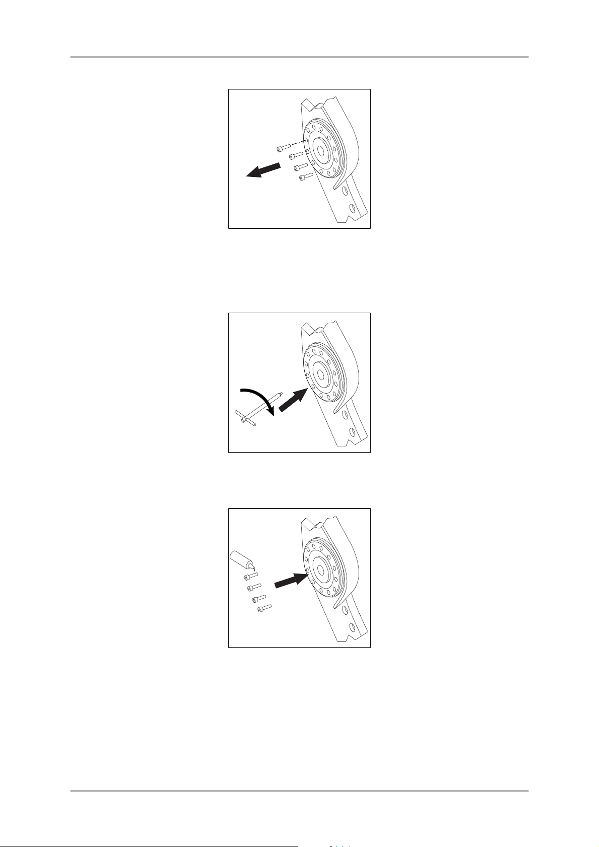
Adjusting regulator clearance recovery RSS05R, RSS08R, RSS11R, RSS15R, RSS23R, RSS34R,
4
RSS45R, RSS58R, RSS80R
4. To make an adjustment, remove the screws on the hinge pivot ring nut.
MB030023
5. After removing all of the screws that block the central pivot ring nut, operate
the adjustment screws that determine the feed to the play recovery flange. The
flange should be resting against the moving shank, without causing exceeding
friction and should not be over tightened.
MB03002
6. Apply Locking fluid to the screws locking the adjusting screws. Fasten the
adjusting screws with the screws at the required torque. NOTICE! Locking
MB030025
fluid ensures a greater seal.
COPYRIGHT © 2019 SANDVIK MINING AND CONSTRUCTION OYPage 60 - Maintenance
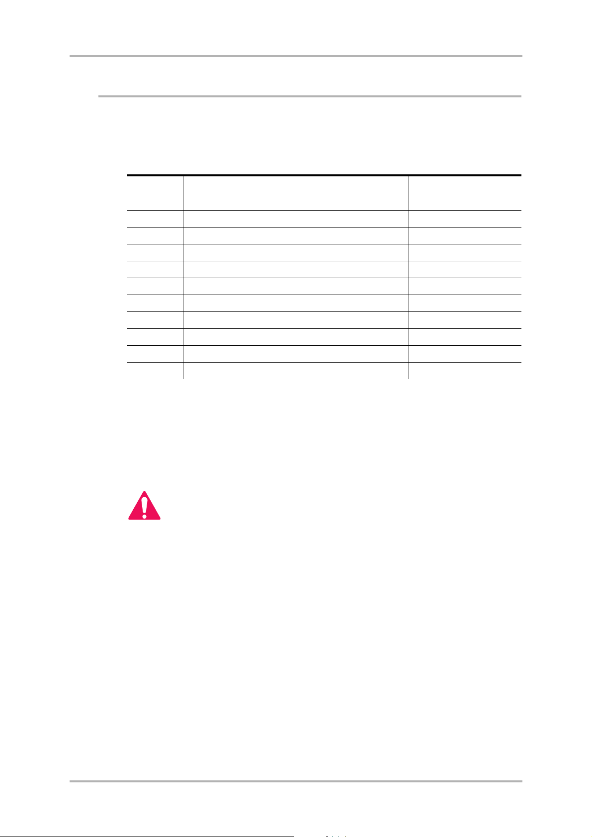
Adjusting regulator lateral guidesRSS05R, RSS08R, RSS11R, RSS15R, RSS23R, RSS34R,
RSS45R, RSS58R, RSS80R
5. ADJUSTING REGULATOR LATERAL GUIDES
TORQUES FOR SCREWS
Screw
M8 25 Nm (18 lbf ft) 35 Nm (26 lbf ft) 42 Nm (31 lbf ft)
M10 50 Nm (37 lbf ft) 70 Nm (52 lbf ft) 85 Nm (63 lbf ft)
M12 85 Nm (63 lbf ft) 120 Nm (89 lbf ft) 145 Nm (107 lbf ft)
M14 135 Nm (100 lbf ft) 190 Nm (140 lbf ft) 230 Nm (170 lbf ft)
M16 210 Nm (155 lbf ft) 295 Nm (218 lbf ft) 355 Nm (262 lbf ft)
M18 290 Nm (214 lbf ft) 410 Nm (302 lbf ft) 490 Nm (361 lbf ft)
M20 410 Nm (302 lbf ft) 575 Nm (424 lbf ft) 690 Nm (509 lbf ft)
M24 710 Nm (524 lbf ft) 995 Nm (734 lbf ft) 1240 Nm (915 lbf ft)
M27 1050 Nm (774 lbf ft) 1450 Nm (1069 lbf ft) 1750 Nm (1291 lbf ft)
M30 1420 Nm (1047 lbf ft) 2000 Nm (1475 lbf ft) 2350 Nm (1733 lbf ft)
ADJUSTING THE REGULATOR LATERAL GUIDES
The product is equipped with a regulator device for the lateral guide of the moving
shank that prevents lateral sliding during operation. You must periodically check
that the regulator is functioning correctly and adjust it as needed.
Tightening torque, grade
8.8
Tightening torque, grade
10.9
Tightening torque, grade
12.9
Prior to maintenance or inspection, operate all the control levers to their fully
extended stroke. This will release pressure within the hydraulic piping and
prevent unexpected movement of the jaw and loss of oil through the hydraulic
lines.
Warning! Support the jaw to prevent it from closing unexpectedly during
maintenance.
1. Position the product on level ground.
2. Support the jaw.
3. Make sure the carrier's transmission is in neutral and the parking brake is
engaged.
Maintenance - Page 61COPYRIGHT © 2019 SANDVIK MINING AND CONSTRUCTION OY

Adjusting regulator lateral guides RSS05R, RSS08R, RSS11R, RSS15R, RSS23R, RSS34R,
MB030026
RSS45R, RSS58R, RSS80R
4. Remove the screws and unscrew the ring nut holding the regulator plug.
5. After removing the ring nut from the regulator plug, turn the regulator which
determines the feed to the play recovery guide. Move the guide forward until it
comes in contact with the shank. Put the ring nut back in place.
MB030027
6. Apply locking fluid to the screws for the ring nut. Fasten the ring nut with the
screws at the required torque. NOTICE! Locking fluid ensures a greater seal.
MB030028
COPYRIGHT © 2019 SANDVIK MINING AND CONSTRUCTION OYPage 62 - Maintenance

RSS45R, RSS58R, RSS80R
6. REPLACING LATERAL GUIDE BUSHING
TORQUES FOR SCREWS
Replacing lateral guide bushingRSS05R, RSS08R, RSS11R, RSS15R, RSS23R, RSS34R,
Screw
M8 25 Nm (18 lbf ft) 35 Nm (26 lbf ft) 42 Nm (31 lbf ft)
M10 50 Nm (37 lbf ft) 70 Nm (52 lbf ft) 85 Nm (63 lbf ft)
M12 85 Nm (63 lbf ft) 120 Nm (89 lbf ft) 145 Nm (107 lbf ft)
M14 135 Nm (100 lbf ft) 190 Nm (140 lbf ft) 230 Nm (170 lbf ft)
M16 210 Nm (155 lbf ft) 295 Nm (218 lbf ft) 355 Nm (262 lbf ft)
M18 290 Nm (214 lbf ft) 410 Nm (302 lbf ft) 490 Nm (361 lbf ft)
M20 410 Nm (302 lbf ft) 575 Nm (424 lbf ft) 690 Nm (509 lbf ft)
M24 710 Nm (524 lbf ft) 995 Nm (734 lbf ft) 1240 Nm (915 lbf ft)
M27 1050 Nm (774 lbf ft) 1450 Nm (1069 lbf ft) 1750 Nm (1291 lbf ft)
M30 1420 Nm (1047 lbf ft) 2000 Nm (1475 lbf ft) 2350 Nm (1733 lbf ft)
REPLACING LATERAL GUIDE BUSHING
Tightening torque, grade
8.8
Tightening torque, grade
10.9
Tightening torque, grade
12.9
Prior to maintenance or inspection, operate all the control levers to their fully
extended stroke. This will release pressure within the hydraulic piping and
prevent unexpected movement of the jaw and loss of oil through the hydraulic
lines.
Warning! Support the jaw to prevent it from closing unexpectedly during
maintenance.
The lateral guide regulator is subject to wear during operation. The buffer has a
bushing that you must replace whenever it is worn.
1. Position the product on level ground.
2. Support the jaw.
3. Make sure the carrier's transmission is in neutral and the parking brake is
engaged.
Maintenance - Page 63COPYRIGHT © 2019 SANDVIK MINING AND CONSTRUCTION OY

Replacing lateral guide bushing RSS05R, RSS08R, RSS11R, RSS15R, RSS23R, RSS34R,
MB030031
RSS45R, RSS58R, RSS80R
4. Lower the moving shank fully on the stationary jaw.
MB030029
5. Unscrew the screws and remove the ring nut. Then unscrew the buffer and
remove it from the surface in contact with the mobile shank.
MB030030
6. Unscrew the screws holding the bushing to the buffer and replace it. Return the
buffer, making contact with the mobile shank.
COPYRIGHT © 2019 SANDVIK MINING AND CONSTRUCTION OYPage 64 - Maintenance

RSS45R, RSS58R, RSS80R
7. Apply locking fluid to the screws for the ring nut. Fasten the ring nut with the
screws at the required torque. NOTICE! Locking fluid ensures a greater seal.
Replacing lateral guide bushingRSS05R, RSS08R, RSS11R, RSS15R, RSS23R, RSS34R,
MB030032
Maintenance - Page 65COPYRIGHT © 2019 SANDVIK MINING AND CONSTRUCTION OY

Changing oil in the rotation unit RSS05R, RSS08R, RSS11R, RSS15R, RSS23R, RSS34R,
RSS45R, RSS58R, RSS80R
7. CHANGING OIL IN THE ROTATION UNIT
DESCRIPTION
C
B
Item
Drain plug (A)
Filler cap (B)
Level plug (C)
CHANGING OIL IN THE ROTATION UNIT
A
MB030033
Warning! Support the jaw to prevent it from closing unexpectedly during
maintenance.
The oil must be changed after the first 150 working hours. Afterwards, it must be
changed every 2000 operating hours or at least once a year.
Change the oil while the rotation unit is hot. Wash the internal parts with the proper
liquids before introducing the new oil.
COPYRIGHT © 2019 SANDVIK MINING AND CONSTRUCTION OYPage 66 - Maintenance

RSS45R, RSS58R, RSS80R
Avoid mixing oils of different viscosity or of different brands. Do not mix mineral
oils with synthetic oils.
After start-up, check the lubricant level periodically and top it up whenever
necessary.
During continuous operation, the temperature of the lubricant must not exceed 80
°C (176 °F). Whenever this value is in danger of being exceeded, forcibly cool the
oil.
NOTICE! Change the oil while the rotation unit is hot.
1. Position the product on level ground. The rotation unit and product must be in
an upright position.
2. Support the jaws.
3. Unscrew the filler cap (B) and the drain plug (A).
4. Completely empty oil in the rotation unit.
5. Replace the drain plug (A).
Changing oil in the rotation unitRSS05R, RSS08R, RSS11R, RSS15R, RSS23R, RSS34R,
6. Remove the level plug (C).
7. Fill the rotation unit with new oil using the filler cap until the oil begins to
overflow from the level plug (C).
8. Replace the filler cap (B) and the level plug (C).
Maintenance - Page 67COPYRIGHT © 2019 SANDVIK MINING AND CONSTRUCTION OY

Troubleshooting RSS05R, RSS08R, RSS11R, RSS15R, RSS23R, RSS34R,
RSS45R, RSS58R, RSS80R
8. TROUBLESHOOTING
8.1 PRODUCT DOES NOT CRUSH
WORN JAW
Perform new hardfacing. See “Hardfacing the jaw” on page 57.
DROP IN HYDRAULIC PRESSURE ON BASE MACHINE
Adjust pressure. See “Product specifications” on page 72.
OIL LEAKAGE WITHIN CYLINDER
The product must be serviced in an authorized Rammer service shop.
8.2 PRODUCT DOES NOT CUT
WORN CUTTING BLADES
Turn over the cutting blades and adjust. If necessary, change the cutting blades. See
“Turning and changing cutting blades” on page 53.
CUTTING BLADE DOES NOT FIT PROPERLY ONTO THE CUTTER BASE
Refit and tighten with bolts. See “Turning and changing cutting blades” on page 53.
INCORRECT CLEARANCE BETWEEN THE BLADES AND BASE
Check the clearance and adjust. See “Turning and changing cutting blades” on page
53.
DROP IN HYDRAULIC PRESSURE ON BASE MACHINE
Adjust pressure. See “Product specifications” on page 72.
OIL LEAKAGE WITHIN CYLINDER
The product must be serviced in an authorized Rammer service shop.
8.3 JAW DOES NOT MOVE
MALFUNCTION IN CARRIER HYDRAULIC SYSTEM
Check the operation of the auxiliary circuit.
BALL VALVES MAY BE CLOSED
Open the ball valves.
JAW MAY BE BLOCKED
Remove obstacles.
OIL LEAKAGE WITHIN CYLINDER
The product must be serviced in an authorized Rammer service shop.
COPYRIGHT © 2019 SANDVIK MINING AND CONSTRUCTION OYPage 68 - Maintenance

RSS45R, RSS58R, RSS80R
CYLINDER ROD IS BENT
The product must be serviced in an authorized Rammer service shop.
8.4 EXCESSIVE MOVING
WORN PINS AND BUSHINGS
The product must be serviced in an authorized Rammer service shop.
8.5 OIL LEAKAGE
OIL LEAKAGE AT HOSE END
Check the hose end and tighten.
OIL LEAKAGE AT SWIVEL JOINT
The product must be serviced in an authorized Rammer service shop.
TroubleshootingRSS05R, RSS08R, RSS11R, RSS15R, RSS23R, RSS34R,
CYLINDER SEALS ARE DAMAGED
The product must be serviced in an authorized Rammer service shop.
8.6 PRODUCT DOES NOT ROTATE
ROTATION IS LOCKED
Open the rotation lock. See “Mounting and dismounting the product” on page 34.
8.7 FURTHER ASSISTANCE
FURTHER ASSISTANCE
If further assistance is required, collect the following information before calling
your dealer:
■ Model and serial number
■ Working hours and service history
■ Carrier model
■ Installation: Oil flow, operating pressure and return line pressure if known
■ Application
■ Has the product operated normally before
Maintenance - Page 69COPYRIGHT © 2019 SANDVIK MINING AND CONSTRUCTION OY

Troubleshooting RSS05R, RSS08R, RSS11R, RSS15R, RSS23R, RSS34R,
RSS45R, RSS58R, RSS80R
COPYRIGHT © 2019 SANDVIK MINING AND CONSTRUCTION OYPage 70 - Maintenance

RSS05R, RSS08R, RSS11R, RSS15R, RSS23R, RSS34R,
RSS45R, RSS58R, RSS80R
SPECIFICATIONS
Specifications - Page 71COPYRIGHT © 2019 SANDVIK MINING AND CONSTRUCTION OY

Product specifications RSS05R, RSS08R, RSS11R, RSS15R, RSS23R, RSS34R,
RSS45R, RSS58R, RSS80R
1. PRODUCT SPECIFICATIONS
1.1 TECHNICAL SPECIFICATIONS RSS05R
Item Specification
Minimum working weight
Weight 345 kg (761 lb)
Max. jaw opening 195 mm (7.68 in)
Max. cutting force 660 kN (148374 lbf)
Cutting force at upper tips 360 kN (80931 lbf)
Operating pressure 200...250 bar (2900...3625 psi)
Oil flow 60...100 l/min (15.9...26.4 gal/min)
Hose connections 3/4" GAS
Operating pressure, rotation 190...200 bar (2755...2900 psi)
Oil flow, rotation 10...15 l/min (2.6...4.0 gal/min)
Connections, rotation 1/2" GAS
Max. diameter to be cut 40 mm (1.57 in)
Jaw closing time at max oil flow 2.4 s
Jaw opening time at max oil flow 1.8 s
No. of cycles per minute at max oil flow 14.3 cycles/min
Optimum oil temperature 40...60 °C (104...140 °F)
Allowed oil temperature range -20...80 °C (-4...176 °F)
1
385 kg (849 lb)
Optimum oil viscosity at operating
temperature
Allowed oil viscosity range 20...1000 cSt
Carrier weight
1. Weight of unit with applicable jaws and standard bracket
2. Check carrier's lifting capacity from carrier manufacturer
2
30...60 cSt
4...6 t (8800...13200 lb)
COPYRIGHT © 2019 SANDVIK MINING AND CONSTRUCTION OYPage 72 - Specifications

RSS45R, RSS58R, RSS80R
1.2 MAIN DIMENSIONS RSS05R
165
Product specificationsRSS05R, RSS08R, RSS11R, RSS15R, RSS23R, RSS34R,
370
150
9020
90
1350
195
200
370
Ø18, 10 pcs
165 20
MB040006
Specifications - Page 73COPYRIGHT © 2019 SANDVIK MINING AND CONSTRUCTION OY

Product specifications RSS05R, RSS08R, RSS11R, RSS15R, RSS23R, RSS34R,
RSS45R, RSS58R, RSS80R
1.3 TECHNICAL SPECIFICATIONS RSS08R
Item Specification
Minimum working weight
1
675 kg (1488 lb)
Weight 605 kg (1334 lb)
Max. jaw opening 290 mm (11.42 in)
Max. cutting force 880 kN (197832 lbf)
Cutting force at upper tips 460 kN (103412 lbf)
Operating pressure 250...300 bar (3625...4350 psi)
Oil flow 80...100 l/min (21.1...26.4 gal/min)
Hose connections 1/2" GAS
Operating pressure, rotation 90...100 bar (1305...1450 psi)
Oil flow, rotation 15...20 l/min (4.0...5.3 gal/min)
Connections, rotation 1/2" GAS
Max. diameter to be cut 50 mm (1.97 in)
Jaw closing time at max oil flow 2.8 s
Jaw opening time at max oil flow 2.0 s
No. of cycles per minute at max oil flow 12.6 cycles/min
Optimum oil temperature 40...60 °C (104...140 °F)
Allowed oil temperature range -20...80 °C (-4...176 °F)
Optimum oil viscosity at operating
30...60 cSt
temperature
Allowed oil viscosity range 20...1000 cSt
Carrier weight
1. Weight of unit with applicable jaws and standard bracket
2. Check carrier's lifting capacity from carrier manufacturer
2
6...9 t (13200...19800 lb)
COPYRIGHT © 2019 SANDVIK MINING AND CONSTRUCTION OYPage 74 - Specifications
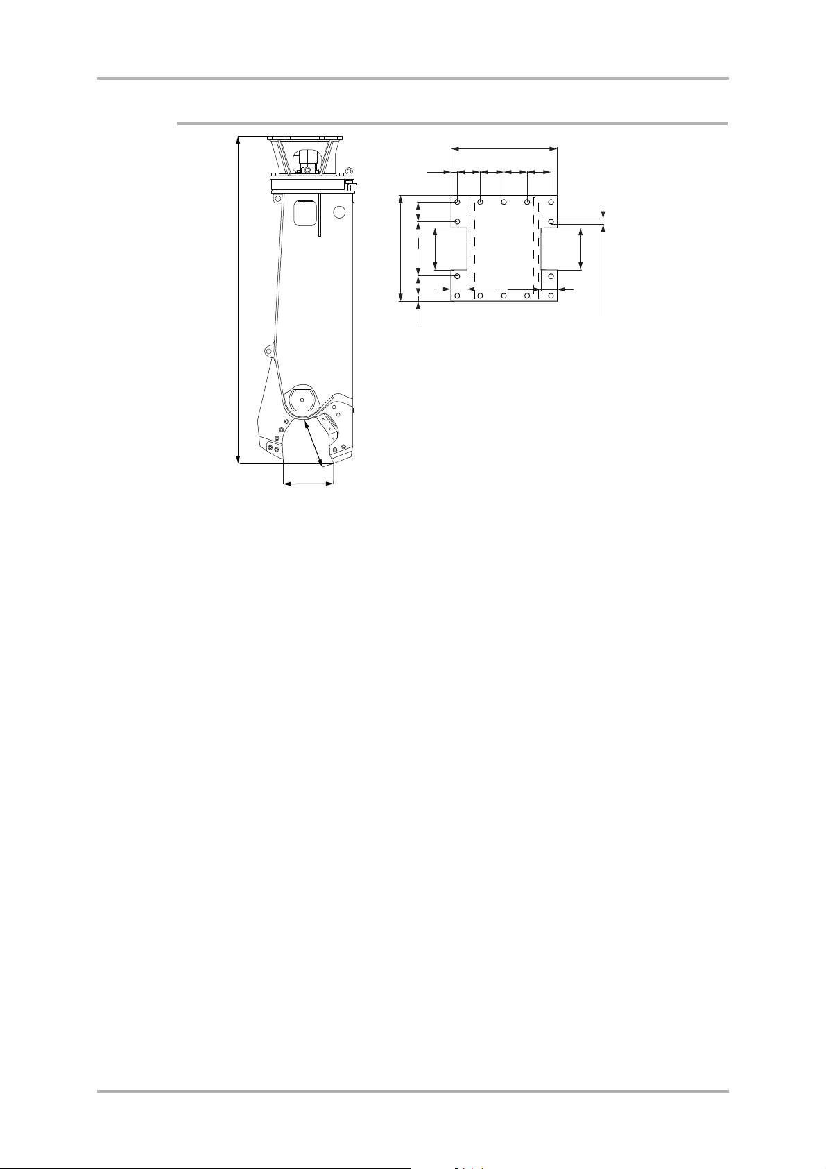
RSS45R, RSS58R, RSS80R
1.4 MAIN DIMENSIONS RSS08R
1900
290
430
80
220
80
25
170
9525
430
95 95
65
Product specificationsRSS05R, RSS08R, RSS11R, RSS15R, RSS23R, RSS34R,
95
170
65
Ø18, 14 pcs
290
MB040007
Specifications - Page 75COPYRIGHT © 2019 SANDVIK MINING AND CONSTRUCTION OY

Product specifications RSS05R, RSS08R, RSS11R, RSS15R, RSS23R, RSS34R,
RSS45R, RSS58R, RSS80R
1.5 TECHNICAL SPECIFICATIONS RSS11R
Item Specification
Minimum working weight
1
1100 kg (2425 lb)
Weight 1010 kg (2227 lb)
Max. jaw opening 375 mm (14.76 in)
Max. cutting force 1380 kN (310236 lbf)
Cutting force at upper tips 550 kN (123645 lbf)
Operating pressure 250...300 bar (3625...4350 psi)
Oil flow 90...110 l/min (23.8...29.1 gal/min)
Hose connections 3/4" GAS
Operating pressure, rotation 190...200 bar (2755...2900 psi)
Oil flow, rotation 10...15 l/min (2.6...4.0 gal/min)
Connections, rotation 1/2" GAS
Max. diameter to be cut 55 mm (2.17 in)
Jaw closing time at max oil flow 2.4 s
Jaw opening time at max oil flow 3.0 s
No. of cycles per minute at max oil flow 11.2 cycles/min
Optimum oil temperature 40...60 °C (104...140 °F)
Allowed oil temperature range -20...80 °C (-4...176 °F)
Optimum oil viscosity at operating
30...60 cSt
temperature
Allowed oil viscosity range 20...1000 cSt
Carrier weight
1. Weight of unit with applicable jaws and standard bracket
2. Check carrier's lifting capacity from carrier manufacturer
2
10...12 t (22000...26500 lb)
COPYRIGHT © 2019 SANDVIK MINING AND CONSTRUCTION OYPage 76 - Specifications

RSS45R, RSS58R, RSS80R
MB040008
2000
375
395
Ø21, 16 pcs
498
550
110
29
110
110
110
125
29
130
130
125
1.6 MAIN DIMENSIONS RSS11R
Product specificationsRSS05R, RSS08R, RSS11R, RSS15R, RSS23R, RSS34R,
Specifications - Page 77COPYRIGHT © 2019 SANDVIK MINING AND CONSTRUCTION OY

Product specifications RSS05R, RSS08R, RSS11R, RSS15R, RSS23R, RSS34R,
RSS45R, RSS58R, RSS80R
1.7 TECHNICAL SPECIFICATIONS RSS15R
Item Specification
Minimum working weight
1
1200 kg (2646 lb)
Weight 1110 kg (2447 lb)
Max. jaw opening 375 mm (14.76 in)
Max. cutting force 1380 kN (310236 lbf)
Cutting force at upper tips 550 kN (123645 lbf)
Operating pressure 250...300 bar (3625...4350 psi)
Oil flow 90...110 l/min (23.8...29.1 gal/min)
Hose connections SAE 6000 psi 3/4"
Operating pressure, rotation 90...100 bar (1305...1450 psi)
Oil flow, rotation 30...40 l/min (7.9...10.6 gal/min)
Connections, rotation 1/2" GAS
Max. diameter to be cut 55 mm (2.17 in)
Jaw closing time at max oil flow 2.4 s
Jaw opening time at max oil flow 3.0 s
No. of cycles per minute at max oil flow 11.2 cycles/min
Optimum oil temperature 40...60 °C (104...140 °F)
Allowed oil temperature range -20...80 °C (-4...176 °F)
Optimum oil viscosity at operating
30...60 cSt
temperature
Allowed oil viscosity range 20...1000 cSt
Carrier weight
1. Weight of unit with applicable jaws and standard bracket
2. Check carrier's lifting capacity from carrier manufacturer
2
13...17 t (28700...37500 lb)
COPYRIGHT © 2019 SANDVIK MINING AND CONSTRUCTION OYPage 78 - Specifications

RSS45R, RSS58R, RSS80R
1.8 MAIN DIMENSIONS RSS15R
498
110
110
29
29
110
125
130
Product specificationsRSS05R, RSS08R, RSS11R, RSS15R, RSS23R, RSS34R,
550
130
125
2000
110
Ø21, 16 pcs
395
375
MB040009
Specifications - Page 79COPYRIGHT © 2019 SANDVIK MINING AND CONSTRUCTION OY

Product specifications RSS05R, RSS08R, RSS11R, RSS15R, RSS23R, RSS34R,
RSS45R, RSS58R, RSS80R
1.9 TECHNICAL SPECIFICATIONS RSS23R
Item Specification
Minimum working weight
1
2130 kg (4696 lb)
Weight 1950 kg (4299 lb)
Max. jaw opening 445 mm (17.52 in)
Max. cutting force 1980 kN (445122 lbf)
Cutting force at upper tips 750 kN (168607 lbf)
Operating pressure 320...350 bar (4640...5075 psi)
Oil flow 150...200 l/min (39.6...52.8 gal/min)
Hose connections SAE 6000 psi 1"
Operating pressure, rotation 130...150 bar (1885...2175 psi)
Oil flow, rotation 30...40 l/min (7.9...10.6 gal/min)
Connections, rotation 1/2" GAS
Max. diameter to be cut 65 mm (2.56 in)
Jaw closing time at max oil flow 1.9 s
Jaw opening time at max oil flow 2.6 s
No. of cycles per minute at max oil flow 13.5 cycles/min
Optimum oil temperature 40...60 °C (104...140 °F)
Allowed oil temperature range -20...80 °C (-4...176 °F)
Optimum oil viscosity at operating
30...60 cSt
temperature
Allowed oil viscosity range 20...1000 cSt
Carrier weight
1. Weight of unit with applicable jaws and standard bracket
2. Check carrier's lifting capacity from carrier manufacturer
2
18...27 t (39700...59500 lb)
COPYRIGHT © 2019 SANDVIK MINING AND CONSTRUCTION OYPage 80 - Specifications

RSS45R, RSS58R, RSS80R
MB040010
2700
445
525
Ø25, 16 pcs
620
137
36
137
137
137
142.5
25 142.5
142.5
620
142.5
1.10 MAIN DIMENSIONS RSS23R
Product specificationsRSS05R, RSS08R, RSS11R, RSS15R, RSS23R, RSS34R,
Specifications - Page 81COPYRIGHT © 2019 SANDVIK MINING AND CONSTRUCTION OY

Product specifications RSS05R, RSS08R, RSS11R, RSS15R, RSS23R, RSS34R,
RSS45R, RSS58R, RSS80R
1.11 TECHNICAL SPECIFICATIONS RSS34R
Item Specification
Minimum working weight
1
3310 kg (7297 lb)
Weight 3100 kg (6834 lb)
Max. jaw opening 565 mm (22.24 in)
Max. cutting force 2860 kN (642954 lbf)
Cutting force at upper tips 1100 kN (247290 lbf)
Operating pressure 320...350 bar (4640...5075 psi)
Oil flow 200...250 l/min (52.8...66.0 gal/min)
Hose connections SAE 6000 psi 1"
Operating pressure, rotation 100...115 bar (1450...1670 psi)
Oil flow, rotation 30...40 l/min (7.9...10.6 gal/min)
Connections, rotation 1/2" GAS
Max. diameter to be cut 85 mm (3.35 in)
Jaw closing time at max oil flow 2.5 s
Jaw opening time at max oil flow 4.3 s
No. of cycles per minute at max oil flow 8.8 cycles/min
Optimum oil temperature 40...60 °C (104...140 °F)
Allowed oil temperature range -20...80 °C (-4...176 °F)
Optimum oil viscosity at operating
30...60 cSt
temperature
Allowed oil viscosity range 20...1000 cSt
Carrier weight
1. Weight of unit with applicable jaws and standard bracket
2. Check carrier's lifting capacity from carrier manufacturer
2
28...39 t (61700...86000 lb)
COPYRIGHT © 2019 SANDVIK MINING AND CONSTRUCTION OYPage 82 - Specifications

RSS45R, RSS58R, RSS80R
1.12 MAIN DIMENSIONS RSS34R
3300
700
30
30
160
160
160
160
160
160
700
160
Product specificationsRSS05R, RSS08R, RSS11R, RSS15R, RSS23R, RSS34R,
160
Ø29, 16 pcs
630
565
MB040011
Specifications - Page 83COPYRIGHT © 2019 SANDVIK MINING AND CONSTRUCTION OY

Product specifications RSS05R, RSS08R, RSS11R, RSS15R, RSS23R, RSS34R,
RSS45R, RSS58R, RSS80R
1.13 TECHNICAL SPECIFICATIONS RSS45R
Item Specification
Minimum working weight
1
4880 kg (10759 lb)
Weight 4560 kg (10053 lb)
Max. jaw opening 670 mm (26.38 in)
Max. cutting force 4130 kN (928461 lbf)
Cutting force at upper tips 1510 kN (339462 lbf)
Operating pressure 320...350 bar (4640...5075 psi)
Oil flow 250...300 l/min (66.0...79.3 gal/min)
Hose connections SAE 6000 psi 1 1/4"
Operating pressure, rotation 100...115 bar (1450...1670 psi)
Oil flow, rotation 30...40 l/min (7.9...10.6 gal/min)
Connections, rotation 1/2" GAS
Max. diameter to be cut 100 mm (3.94 in)
Jaw closing time at max oil flow 4.0 s
Jaw opening time at max oil flow 5.0 s
No. of cycles per minute at max oil flow 6.7 cycles/min
Optimum oil temperature 40...60 °C (104...140 °F)
Allowed oil temperature range -20...80 °C (-4...176 °F)
Optimum oil viscosity at operating
30...60 cSt
temperature
Allowed oil viscosity range 20...1000 cSt
Carrier weight
1. Weight of unit with applicable jaws and standard bracket
2. Check carrier's lifting capacity from carrier manufacturer
2
39...50 t (86000...110200 lb)
COPYRIGHT © 2019 SANDVIK MINING AND CONSTRUCTION OYPage 84 - Specifications

RSS45R, RSS58R, RSS80R
1.14 MAIN DIMENSIONS RSS45R
3700
800
30
30
148
148
148
148
170
170
740
170
Product specificationsRSS05R, RSS08R, RSS11R, RSS15R, RSS23R, RSS34R,
170
Ø32, 18 pcs
720
670
MB040012
Specifications - Page 85COPYRIGHT © 2019 SANDVIK MINING AND CONSTRUCTION OY

Product specifications RSS05R, RSS08R, RSS11R, RSS15R, RSS23R, RSS34R,
RSS45R, RSS58R, RSS80R
1.15 TECHNICAL SPECIFICATIONS RSS58R
Item Specification
Minimum working weight
1
5880 kg (12963 lb)
Weight 5560 kg (12258 lb)
Max. jaw opening 760 mm (29.92 in)
Max. cutting force 4780 kN (1074587 lbf)
Cutting force at upper tips 1850 kN (415897 lbf)
Operating pressure 320...350 bar (4640...5075 psi)
Oil flow 275...375 l/min (72.6...99.1 gal/min)
Hose connections SAE 6000 psi 1 1/4"
Operating pressure, rotation 100...115 bar (1450...1670 psi)
Oil flow, rotation 30...40 l/min (7.9...10.6 gal/min)
Connections, rotation 1/2" GAS
Max. diameter to be cut 110 mm (4.33 in)
Jaw closing time at max oil flow 4.3 s
Jaw opening time at max oil flow 5.3 s
No. of cycles per minute at max oil flow 6.2 cycles/min
Optimum oil temperature 40...60 °C (104...140 °F)
Allowed oil temperature range -20...80 °C (-4...176 °F)
Optimum oil viscosity at operating
30...60 cSt
temperature
Allowed oil viscosity range 20...1000 cSt
Carrier weight
1. Weight of unit with applicable jaws and standard bracket
2. Check carrier's lifting capacity from carrier manufacturer
2
51...65 t (112400...143300 lb)
COPYRIGHT © 2019 SANDVIK MINING AND CONSTRUCTION OYPage 86 - Specifications

RSS45R, RSS58R, RSS80R
MB040013
3950
760
780
Ø32, 18 pcs
800
148
30
148
148
148
170
30
170
170
740
170
1.16 MAIN DIMENSIONS RSS58R
Product specificationsRSS05R, RSS08R, RSS11R, RSS15R, RSS23R, RSS34R,
Specifications - Page 87COPYRIGHT © 2019 SANDVIK MINING AND CONSTRUCTION OY

Product specifications RSS05R, RSS08R, RSS11R, RSS15R, RSS23R, RSS34R,
RSS45R, RSS58R, RSS80R
1.17 TECHNICAL SPECIFICATIONS RSS80R
Item Specification
Minimum working weight
1
8265 kg (18221 lb)
Weight 7565 kg (16678 lb)
Max. jaw opening 830 mm (32.68 in)
Max. cutting force 5520 kN (1240945 lbf)
Cutting force at upper tips 2150 kN (483339 lbf)
Operating pressure 320...350 bar (4640...5075 psi)
Oil flow 500...600 l/min (132.1...158.5 gal/
min)
Hose connections SAE 6000 psi 1 1/2"
Operating pressure, rotation 140...150 bar (2030...2175 psi)
Oil flow, rotation 50...60 l/min (13.2...15.9 gal/min)
Connections, rotation 1/2" GAS
Max. diameter to be cut 130 mm (5.12 in)
Jaw closing time at max oil flow 2.8 s
Jaw opening time at max oil flow 4.8 s
No. of cycles per minute at max oil flow 7.9 cycles/min
Optimum oil temperature 40...60 °C (104...140 °F)
Allowed oil temperature range -20...80 °C (-4...176 °F)
Optimum oil viscosity at operating
30...60 cSt
temperature
Allowed oil viscosity range 20...1000 cSt
Carrier weight
1. Weight of unit with applicable jaws and standard bracket
2. Check carrier's lifting capacity from carrier manufacturer
2
70...90 t (154300...198400 lb)
COPYRIGHT © 2019 SANDVIK MINING AND CONSTRUCTION OYPage 88 - Specifications

RSS45R, RSS58R, RSS80R
1.18 MAIN DIMENSIONS RSS80R
830
840
1140
70
165
170
165
165
170
165
22560
4300
1020
225 225
Product specificationsRSS05R, RSS08R, RSS11R, RSS15R, RSS23R, RSS34R,
225
Ø39, 20 pcs
MB040030
Specifications - Page 89COPYRIGHT © 2019 SANDVIK MINING AND CONSTRUCTION OY

EC Declaration of Conformity RSS05R, RSS08R, RSS11R, RSS15R, RSS23R, RSS34R,
RSS45R, RSS58R, RSS80R
2. EC DECLARATION OF CONFORMITY
EC DECLARATION OF CONFORMITY
Manufacturer: MANTOVANIBENNE S.R.L.
Address: VIA RIGHI, 6 41037 MIRANDOLA (MO), ITALY
Declares under our sole responsibility that the interchangeable product:
Rammer scrap shear
Model: RSS05S
Model: RSS08S
Model: RSS11S
Model: RSS15S
Model: RSS23S
Model: RSS34S
Model: RSS45S
Model: RSS58S
Model: RSS80S
Model Serial number Reference number
RSS05R SS05RA
RSS08R SS08RA
RSS11R SS11RA
RSS15R SS15RA
RSS23R SS23RA
RSS34R SS34RA
RSS45R SS45RA
RSS58R SS58RA
RSS80R SS80RA
Place of issue: Mirandola, Italy
Date of issue: dd.mm.yyyy
to which this declaration relates, conforms to the Basic Safety and Health Requirements of Directive 2006/42/
EC.
Harmonized standards applied: EN474-1; EN474-5; EN12100-1; EN12100-2
Other standards applied: ISO 10567/92; ISO 7451/83; SAE J1097; DIN 15019; DIN 24086
Name and position of issuer: N.N
Signature of issuer: N.N
Issuer of technical dossier: M.M Via A. Righi, 6 41037 Mirandola (MO) Italy
Original
COPYRIGHT © 2019 SANDVIK MINING AND CONSTRUCTION OYPage 90 - Specifications

Page 91COPYRIGHT © 2019 SANDVIK MINING AND CONSTRUCTION OY

®
75-12-14133-42-20-343
78-12-14133-24-92-0
Sandvik Mining and Construction Oy, Breakers Lahti
Taivalkatu 8, P.O. Box 165, FI-15101 Lahti, Finland
Phone Int. +358 205 44 151, Telefax Int. +358 205 44 150
www.rammer.com
 Loading...