


®
A Complete Heat Trace Control Solution
HTAS/HTLS
Series 8000/12000/24000
Chromalox
Heat Trace Control Panel
Setup Guide
PK485-2
0037-75423
December 2008

Welcome to Chromalox
®
intelliTRACE
TM
– a complete heat trace control solution with industry-best
price and performance.
For more than 80 years, customers have relied on Chromalox for the utmost in quality and innovative solutions for industrial heating applications. Chromalox manufactures the world’s largest and
broadest line of electric heat and control products.
intelliTRACE provides the user with an easy touch-screen interface, continuous built-in monitoring,
line (HTLS) or ambient (HTAS) sensing, scalability, and customization.
TM
intelliTRACE
specifi cations include:
• Color Touchscreen Operator Panel with Global Programming
• Temperature, Current, Output and Alarm Display for Each Control Loop
• 8/12/24 Points of Power Control
• HTAS – Ambient Sensing or Line
Sensing Controllers
• HTLS – Line Sensing Includes
Independent On/Off Control
for Each Loop With Adjustable
Deadband and Open Sensor
Alarm with Programmable Output
• Auto-Cycle Feature, Programmable to 720 Hours
• HTLS – High/Low Temperature
Alarms Included in Line Sensing
Version
• Programmable Low Current
Alarm for Each Loop
• Ground Fault Alarm/Trip, Adjustable from 30 to 300 mA
• Common Alarm Output
• Three-Phase Supply Options of 120/208, 240, 277/480
• Load Management: 15 sec. Non-Overlap to Reduce Inrush
• RS-485 Network Communications MODBUS Slave
• NEMA 4 Enclosure
• Operating Environment: 32-120°F
We think you’ll be satisfi ed with the high quality product Chromalox has shipped to you. If you have
application questions, refer to the Engineering Resource section of our website at www.chromaloxheating.com, to fi nd the answer you’re looking for, or call one of our application engineers at 1-888996-9258 for personal assistance.
- 1 -

- 2 -

Table of Contents
Safety Precautions ................................................................................................................................ 4
intelliTRACETM Main Menu .....................................................................................................................5
Global Process Settings ................................................................................................................. 7
Setting User Preferences with Global Process Settings ................................................................. 7
Setting Temperature Preferences ................................................................................................... 8
Applying Temperature Limits .......................................................................................................... 8
Global Setpoint and Deadband .................................................................................................... 10
Global Alarm Setpoints ................................................................................................................. 11
Setting High and Low Temperature Alarms ............................................................................ 11
Chart Range .................................................................................................................................. 13
Applying Communication Settings ...............................................................................................14
Setting Baud Rate .................................................................................................................. 14
Selecting Parity ...................................................................................................................... 15
Address ................................................................................................................................. 15
RTS On/Off Delay ................................................................................................................... 15
II. Setting Loop Parameters .............................................................................................................. 16
Global ON/OFF ....................................................................................................................... 18
Applying Setpoint for an Individual Loop ............................................................................... 19
Setting Deadband for an Individual Loop ............................................................................... 20
Applying Loop Identifi cation Text ........................................................................................... 21
Resetting Loop Identifi cation Text to Factory Defaults .......................................................... 22
Alarm Indicators ..................................................................................................................... 23
Types of Alarm Indicators ................................................................................................ 23
– Output ........................................................................................................................... 23
– High Temperature ..........................................................................................................23
– Low Temperature .......................................................................................................... 24
– Low Current................................................................................................................... 24
– Ground Fault ................................................................................................................. 24
– RTD ............................................................................................................................... 24
Additional Loop Settings .................................................................................................. 24
– Hi/Lo Alarm ................................................................................................................... 25
– RTD Fault % Output ...................................................................................................... 26
Applying a Low Amp Set Point for an Individual Loop ........................................................... 27
– Ground Fault Isolation Button ....................................................................................... 28
– Loop Active Button ....................................................................................................... 28
III. Operating the Loops ..................................................................................................................... 29
IV. intelliTRACETM Utilities .................................................................................................................. 30
Adjusting Brightness/Contrast for the Touchscreen ..................................................................... 32
Setting Auto Cycle for Ground Fault Testing ................................................................................ 33
V. intelliTRACETM Alarm Status Indicators ......................................................................................... 35
Alarm Status ................................................................................................................................. 35
Loop Status .................................................................................................................................. 36
View Graph ................................................................................................................................... 38
Appendix
Theory of Operation .....................................................................................................................A.3
- 3 -

Safety Precautions
Important Safeguards
Throughout the intelliTRACETM Setup Guide, these symbols will alert you to potential hazards. Safety precautions should always be followed to reduce the risk of
fi re, electrical shock, and injury to persons.
TM
Please read all instructions before operating your intelliTRACE
To avoid electrical shock or injury, always remove power before servicing a circuit.
Personnel working with or near high voltages should be familiar with modern methods of resuscitation. Contact an area supervisor or safety personnel for more information.
HTLS/HTAS Control Panel.
- 4 -
intelliTRACETM Safety Precautions
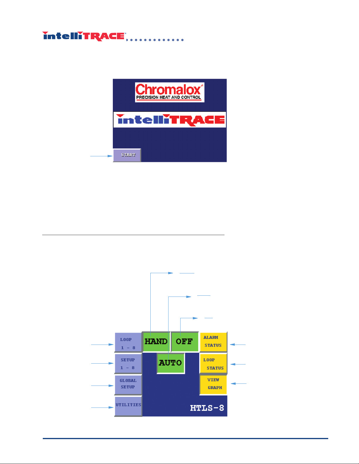
Main Menu
intelliTRACETM provides users with an easy-to-use touchscreen interface. Getting into the system
is as simple as touching the “start” button on the initial screen, as seen below.
TM
The Start button takes the user to the Main Menu of intelliTRACE
Press “Start” on
the touchscreen
to enter the intelliTRACE
TM
system.
from several function buttons (displayed in purple), including loop setup options, loop parameter
options, global setup options, and utilities options. The main menu also includes status buttons
(displayed in yellow) which allow the user the option to view alarm status, loop status, and graphs
depicting system performance.
, where the user can choose
Three indicating pushbuttons (displayed in green) show the current system status:
Setting User Preferences with Global Process Settings
❲
Hand: Indicates that the system is currently operat-
ing in manual mode.
Auto: Indicates that the system is currently
operating in automatic mode.
Off: Indicates that the system is currently
off.
Selects individual
loop display
Sets individual loop
parameters
Selects global
parameters
Features
system performance and
monitoring
information
Displays active alarms and
alarm status
Displays active loop and loop
status
Displays setpoint and
temperature of each loop.
intelliTRACETM Main Menu
- 5 -

Main Menu
Selects individual
loop display
Sets individual loop
parameters
Features system
performance and
monitoring
information
Press for Communication Setting
Hand: Indicates that the system is currently operat-
ing in manual mode.
Auto: Indicates that the system is currently
operating in automatic mode.
Off: Indicates that the system is currently
off.
Displays active alarms and
alarm status
Displays active loop and loop
status
- 6 -
intelliTRACETM Main Menu

I. Global Process Settings
The Global Process Settings panel establishes setpoint, deadband, high and low temperatures,
alarm settings, communications settings, and graphic display for temperature.
Settings made on the Global Process Settings screens provide operating ranges for the entire
system, and defi ne the parameters in which the system will operate. The system will not allow the
user to set temperatures on individual loops outside the limit of the temperatures set forth in the
Global Process Settings. Please use caution when applying the Global Process Settings. On the
main menu, press the “Global Setup” area of the touchscreen:
1. Touch the “Global
Setup” button on
the touchscreen.
intelliTRACE™ has built-in security settings that require a password for access to the Global Setup
screen. A keypad is displayed, requiring the user to enter a password:
2. Use the touchscreen
keypad to enter a
3-digit password.
(factory preset password: 458 cannot be
changed)
3. Touch “ENT” to enter
the password.
Upon entering the correct password, the user is permitted to access the Global Setup screen.
intelliTRACETM Global Process Settings
- 7 -

Setting Temperature Preferences
The intelliTRACETM system supports both Celsius and Fahrenheit temperatures, and will automatically convert from C to F and vice versa if the temperature units are changed. Before proceeding
with the setup of Global Process Settings, fi rst choose a temperature unit by choosing either C
(Celsius) or F (Fahrenheit) for the preferred unit of measure.
Celsius
Fahrenheit
The temperature unit chosen and entered will automatically convert all existing temperatures accordingly.
Applying Temperature Limits
High and low temperature limits are set in the global settings section. This provides a limited
range for temperature and setpoint. To change the limits for high and low temperature parameters
TM
in the intelliTRACE
system, press the “Set Limits” button.
- 8 -
1. Press the “Set Limits”
button on the touchscreen
intelliTRACETM Global Process Settings

Top display veri-
fi es data entered
in the lower
display.
Top display verifi es
data entered in the
lower display.
Touch bottom
display to set
high temperature
limit.
Touch bottom display
to set low temperature
limit.
The “Temperature Limits” screen defi nes the values for the high and low temperature that the system will work within. Global temperature limits set the high and low temperatures under which the
entire system will operate. The system will not allow the user to set temperature setpoints on indi-
vidual loops outside the range set forth in the global temperature limits. Temperatures for Celsius
begin at 0°C, but cannot exceed 500°C. Temperatures for Fahrenheit begin at 32°F, but cannot
exceed 950°F.
Maximum Span of Temperature
Low
High
Celsius
0° 32°
500°
Fahrenheit
950°
IMPORTANT: High and low temperatures defi ned in loops may not exceed
the high and low temperatures defi ned in the Global Settings!
1. Press the lower display on the High Limit and Low Limit settings, and a keypad will display:
2. Use the touchscreen keypad to
enter temperature.
3. Touch “ENT” to
enter the value.
Press “Return” to return to the main Global settings screen.
intelliTRACE
TM
Global Process Settings
- 9 -

Global Setpoint and Deadband
Setpoint
Setpoint temperature is the control temperature to be maintained throughout the process and is
set by the operator.
Global Setpoint, Deadband, and High/Low Alarms are the common settings available to be used
throughout the process.
To apply a global setpoint, press the display to the right of “Setpoint” on the Global Process Settings screen:
1. Touch the display
to the right of
“setpoint.” A keypad will display.
2. Use the touchscreen to enter
setpoint temperature.
3. Touch “ENT” to
enter the value.
The entered setpoint temperature will display.
The setpoint temperature chosen (122° in the above example) will be used if/when the system is in
“auto” mode, and an individual loop is changed to accept global settings.
- 10 -
intelliTRACETM Global Process Settings
Deadband
Deadband settings allow for a small area of fl uctuation between the point when the system activates and when the system reaches the control temperature. It is a range of the variable in which
no corrective action is taken by the system. For example, if the setpoint temperature is at 100°,
and deadband is set at 2, the heat output will activate when the temperature drops below 100°, and
deactivate when the temperature reaches 102°. Deadband is measured in units ranging from 0-10.
1. Touch the display to the right of the word “Deadband.”
2. Use the touchscreen
to enter the number
of deadband units.
3. Touch “ENT” to enter
the value.
The entered Deadband units will be displayed.
Global Alarm Setpoints
The intelliTRACETM system provides global setpoints for high/low temperature alarms.
Setting High and Low Temperature Alarms
To set Global Alarm Parameters, press the “Set Alarms” button on the touch-screen in the main
Global Process Settings menu.
1. Press the
“Set Alarms” button
on the touchscreen
intelliTRACETM Global Process Settings
- 11 -

The “Set Alarms” screen defi nes the global high and low temperature alarm setpoints. Any temperature that exceeds these setpoints will result in an alarm activation.
2. Touch display to the
right of “High T
set High Temp Alarm.
3. Touch display to the right
of “Low Temp” to set Low
Temp Alarm.
emp” to
IMPORTANT: High and low temperatures defi ned in loops may not exceed
the high and low temperatures defi ned in the global limits!
1. Touch the display to the right of “High Temp” and “Low Temp,” and a keypad will display.
2. Use the touchscreen keypad to
enter temperature.
3. Touch “ENT” to
enter the value.
The entered high and low alarm tem-
peratures will be displayed.
Press “Return” to return to the main Global Process Settings screen.
- 12 -
intelliTRACETM Global Process Settings

Chart Range
One of the features of the intelliTRACETM system is a visual display of system performance. Depending upon the temperatures your particular process requires, there are a variety of temperature
ranges to choose from. For instance, if your process has high temperatures of 400°F, the most
appropriate chart would be the 0°-500°F chart range. Choosing a range of 0-1000°F would offer
less resolution.
On the main Global Process Settings page, touch the “Select Chart” button.
1. Press the “Select
Chart” button on the
touchscreen.
Use the touchscreen to choose the temperature range that is most appropriate for your process.
2. Choose the most appropriate temperature range for
your process.
Note: This selection is the default display. Other chart ranges can be selected while on the default chart display.
Press “Return” to return to the main Global Process Settings screen.
intelliTRACE
TM
Global Process Settings
- 13 -

Applying Communication Settings
The HTLS/HTAS Control Panel can be programmed and monitored by connecting it with a person-
TM
nel computer, PLC or DCS. intelliTRACE
operates as a ModBus slave. Baud Rate, Parity, Stop Bits, and Station address must be set in
accordance with the type of software being used. We suggest you check with information system
professionals regarding the type of hardware and communications settings your hardware requires.
To access the communications settings, press the “Set Port 2” button on the Global Process Settings screen.
1. Press “Set Port 2” for
communications settings.
features RS485 ModBus Network Communications and
Setting Baud Rate
The data format and communications format are easily set by the Port 2 Setup screen.
Select the corresponding baud rate on the “Set Port 2” screen.
1. Press the touch-screen
to select baud.
The selected baud rate
will illuminate.
- 14 -
intelliTRACETM Global Process Settings

Selecting Parity
Press the touch-screen
to select stop bit.
1. Press the touch-screen
to select parity.
The selected parity will
illuminate.
Address
The address is the station address for the ModBus Communications. The station must be a unique
address. (1-247, default is 1)
RTS On/Off Delay
The RTS On/Off Delay portion of the Comm screen is not applicable, and does not require any action on the part of the user.
intelliTRACETM Global Process Settings
- 15 -
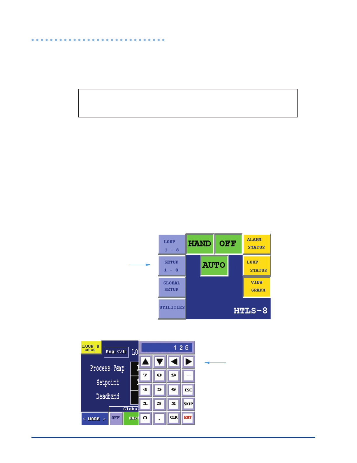
II. Setting Loop Parameters
intelliTRACETM HTLS/HTAS features three different models with either 8, 12 or 24 programmable
loops in which the user can program deadband, setpoint, high and low temperature alarm, RTD
fault percent of output, and override individual loops settings with global settings.
The intelliTRACE system features continuous monitoring of the entire
&
The “Setup 1-8” option also provides status monitoring and alarms for high/low temperature, continuity, ground fault leakage and sensor faults. Monitoring is controlled by an auto-cycle function
that periodically checks each loop for problems.
Operators have the choice of using the global setup values or setting individual loop parameters
(see “Global Settings,” pg. 7).
To set up individual loop parameters, touch the “Setup 1-8” button on the touchscreen.
system and activates alarms when potential trouble spots are reported.
The loop setup function requires the user to enter a password and a keypad will display.
1. Touch the “Setup
1-8” button on the
touch-screen.
2. Use the touchscreen
keypad to enter the
3-digit factory preset
password 458 (cannot
be changed).
- 16 -
3. Touch “ENT” to enter
the password.
intelliTRACETM Setting Loop Parameters

The main screen on “Setup 1-8” features process temperature, setpoint, deadband, and loop/text
values.
The main screen also indicates High/Low temp, current, ground fault, and open sensor alarm conditions.
Directs user to previous
loop for programming.
Displays
temperature
range as either C or F.
Shows loop
number or allows
user to set text
identifi cation.
Advances to next loop
for programming.
Shows process
temperature.
Allows user
to set
setpoint and
deadband.
More: Contains
settings for high/low
alarm, RTD fault %
output, and low amp
alarm setpoint
Global Set: Allows user to override individual loop setting with
Global Settings.
Output “ON” Indicator
Alarm indicators notify user of
potential hazard with fl ashing
alarm conditions:
• High Temperature
• Low Temperature
• Low Current
• Ground Fault Leakage
• RTD Fault
Menu: Takes user to the main
intelliTRACE screen.
intelliTRACETM Setting Loop Parameters
- 17 -

Global ON/OFF
The Global ON/OFF portion of the main “Setup 1-8” screen allows the user to override individual
loop settings with Global Settings previously applied in the Global Process Settings section (see
“Global Process Settings, p. 5).
Global Settings can override individual loop settings by touching the “ON” button.
Touching the “OFF” button allows individual loop
settings to be made.
The “ON” display will illuminate if Global settings
are active.
To override loop settings, press the “ON” button (far right) under “Global Set.” To disable global
settings, press the “OFF” button (far left) under Global Set.
Disables Global Settings
Enables Global Settings
Illuminates when Global Settings are active
The “ON/OFF” display in the middle of “Global Set” shows the status of the global settings. If
global settings are active, the “ON” display will illuminate. If global settings are inactive, the “OFF”
display will illuminate.
- 18 -
intelliTRACETM Setting Loop Parameters

Applying Setpoint for an Individual Loop
Loop number (i.e.,
“LOOP 3”) or loop
indentifi cation text is
displayed above the
process temperature.
IMPORTANT: The system displays “LOOP _” above the process
temperature box so the user knows which loop is being set. Please ensure
that you are in the correct loop screen before making any changes!
Setpoint is the temperature at which the user wants the loop to operate. A temperature is set by
touching the display to the right of “setpoint.”
1. Press the display to
the right of “setpoint.”
A keypad will display.
2. Use the keypad to
enter the setpoint
temperature.
3. Touch “ENT” to
enter the value.
The setpoint will be displayed.
IMPORTANT: Be sure to check temperature unit (Celsius or Fahrenheit)
before entering temperature!
intelliTRACETM Setting Loop Parameters
- 19 -

Setting Deadband for an Individual Loop
To set deadband for an individual loop, press the display to the right of “Deadband.”
1. Press the display to
the right of “deadband.”
A keypad will display.
2. Use the keypad to
enter the deadband units.
3. Touch “ENT” to
enter the value.
The deadband units will
be displayed.
- 20 -
intelliTRACETM Setting Loop Parameters

Applying Loop Indentifi cation Text
TM
IntelliTrace
provides users a feature to label each loop with a unique name or identifi cation tag
in lieu of the factory default settings of loop 1 through loop 24. Text identifi cation has a maximum
character length of fourteen characters and is left justifi ed. You can use spaces (SPC) to center
text.
Touch “Loop 1” on the touch screen to
enter the text identifi cation feature
A keyboard is displayed. Enter
the text. Touch “ENT” to enter
the text.
intelliTRACETM Setting Loop Parameters
- 21 -

Resetting Loop Identifi cation Text to factory Defaults
This function overrides all loop identifi cation text with “Loop 1, Loop 2”, etc.
Touch to reset Loop I.D to Loop 1, etc.
- 22 -
intelliTRACETM Setting Loop Parameters

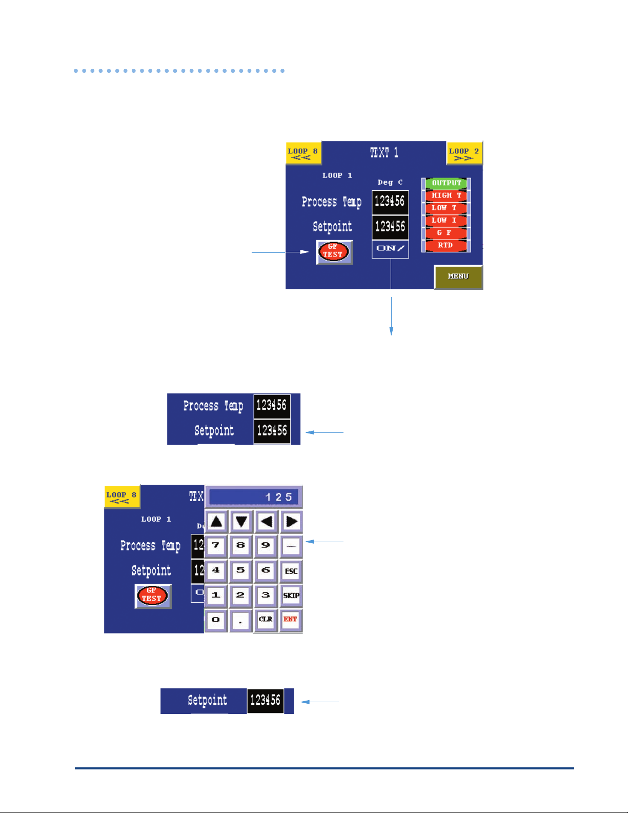
Alarm Indicators
Alarm indicators exist in the Setup 1-8, Loop 1-8, and Alarm Status screens, and alert the user
TM
to potential problems within the intelliTRACE
system such as high and low temperature, low
current, ground fault, and RTD (resistance temperature detection) fault. If the system detects an
alarm, it alerts the operator with both visual display and alarm contact.
The alarm indicators in both the Setup 1-8 and Loop 1-8 screens have a series of displays on the
right side of the screen that will fl ash in the case of a problem.
Displays will fl ash and
alarm contacts will close
in the event of an alarm.
The output indicator alerts the user when the system is running, i.e., when the heat is on. The
output indicator will let the operator know when output is occurring in each loop. For instance,
if loops 5 and 8 have active output, the Output display on loops 5 and 8 will be illuminated. The
display in other loops, however, will not be illuminated.
The high temperature display will fl ash if the system detects that a high temperature has been
reached or exceeded.
For instance, if the operator is running an individual loop setting on Loop 4, and the high
temperature for the loop is set at 100°F, and the temperature reaches 100°F, the alarm will fl ash
and the common alarm contact will close.
intelliTRACETM Setting Loop Parameters
- 23 -

Corrective action must be taken in the event that an alarm sounds.
Check with the Supervisor in your area to review emergency plans.
Much like the high temperature display, the low temperature display will fl ash if the system detects
that a low temperature has been reached or exceeded.
For instance, if the operator is running an individual loop setting on Loop 2, and the low
temperature for the loop is set at 100°F, and the temperature reaches 100°F, the alarm will fl ash
and the common alarm contact will close.
The low current display fl ashes when a low current is detected within the system. If the system
detects a low current when conducting regular maintenance testing, the display will fl ash and the
common alarm contact will close. Corrective action must be taken.
The ground fault display fl ashes when a ground fault condition is detected within the
intelliTRACE™ system. If the system is idle (no outputs on), ground fault tests are conducted
TM
regularly as defi ned by the operator in the Utilities screen (see “intelliTRACE
Utilities,” p. 32).
Indicates RTD (Resistance Temperature Detection) fault. If the system detects a fault in the RTD
sensor, the display will fl ash and the common alarm contact will close.
Additional Loop Settings
The “More” button directs the user to an additional screen that allows high
and low alarm temperatures to be set for the current loop. High and low
temperatures can be set for individual loops, however, the temperatures
cannot exceed the high and low temperatures set forth in the global process limits (see
“Global Process Settings,” p. 5).
- 24 -
intelliTRACETM Setting Loop Parameters

To set the high and low temperature alarms, press the display to the right of “Hi-Alarm” or “LoAlarm.”
1. Press the display to the
right of “Hi-Alarm” and
“Lo-Alarm” to set the
maximum and minimum temperature the
loop will allow before
activating an alarm.
A keypad will display.
2. Use the keypad
to enter the alarm
temperature.
3. Touch “ENT” to
enter the value.
The alarm temperature will be displayed.
intelliTRACETM Setting Loop Parameters
- 25 -

RTD Fault - Percent of Output
In the event of an RTD fault the output will automatically revert to a selected value (factory set
at 0%). The output of the loop can be programmed to any level between 0% and 100%. This is
based on what is appropriate for the process. To set the RTD fault % output, touch on “MORE” on
the Setup 1-8 main screen.
1. Touch the RTD Fault % Output
display to enter the percentage of
output the system will default to in
the event of a RTD fault.
- 26 -
2. Enter the percentage of output at
which the system should operate in
the event of an RTD fault.
3. Press “ENT” to enter the value.
The percentage of RTD fault
output will be displayed.
intelliTRACETM Setting Loop Parameters

Applying a Low Amp Alarm Setpoint for an Individual Loop
The low amp alarm actuates when the current is equal to or less that the alarm setpoint. The low
amp setpoint can be programmed to any value between .3 - 24.0 amps.To set the low amp alarm
setpoint, touch on “MORE” on the setup 1-8 main screen.
1. Touch the “Low Amp Alarm SP” display to enter the low amp setpoint. A
keypad will display
intelliTRACETM Setting Loop Parameters
2. Use the keypad to enter the low amp
setpoint.
3. Touch “ENT” to enter the value
- 27 -

Ground Fault Isolation Button
The intelliTRACE Panel in a normal operations mode conducts a “standard ground fault and current measurement” every 20 minutes. In the “Standard Test” each loop is tested for 5 seconds.
In the event a ground fault is detected the “Standard Test” is performed and the faulted circuit is
isolated. In isolation mode no power is applied to that loop. To reset isolation the fault must be
cleared and the “Standard Test” must be run (see Utilities pg. 30).
If the ground fault isolation button is turned “OFF” while a ground fault exists, a “Ground Fault Only
Test” is performed every 2.5 minutes. Each loop is tested for one second.
HTLS Screen HTAS Screen
Returns user to
previous screen.
Overrides the
ground fault
isolation
Display illuminates
“GFI ON” when
ground fault is being
conducted and “GFI OFF”
when off. (Red)
Display illuminates
“GFI ON” when
ground fault is being
conducted and “GFI OFF”
when off. (Red)
IMPORTANT: To change settings on additional loops, press the “Loop”
buttons in the upper right and left corners of the Setup
1-8 Screen! Always check to make sure you are
making changes to the correct loop!
Loop Active Button
HTLS Screen HTAS Screen
Display illuminates “ACTIVE”
when loop is active and “INACTIVE” when loop is off.
To enable or disable a control loop the “Loop”
switch is used to turn “OFF” or “Activate” the loop.
- 28 -
Display illuminates
“ACTIVE” when loop is active
and “INACTIVE” when loop is off.
intelliTRACETM Setting Loop Parameters
III. Operating the Loops
Once the loops have been setup in “Setup” (see “Setting Loop Parameters,” p. 14), you can program individual loops (HTLS only), which only involves entering a setpoint.
Setpoint is the only programmable area on the “Setup”
screen. All other areas of the
screen are informational.
Indicates “Ground Fault Test”
in process.
Indicates “Active” or “Inactive” loop.
1. Press the display
to the right of “Setpoint.”
A keypad will display.
2. Use the keypad to
enter the setpoint
temperature.
3. Touch “ENT” to
enter the value.
The entered setpoint will
be displayed.
intelliTRACETM Operating The Loops
- 29 -

Utilities
intelliTRACE™ features utilities that allow the user to obtain a visual indication of how the system
is performing at any given time. Here, the user can conduct a manual ground fault test, set
the auto cycle for intermittent ground fault testing, check loop status for output, and adjust the
contrast for screen appearance. There is also a digital and graphic display of electrical current.
&
The intelliTRACE™ system provides utilities that allow the user to increase
productivity by spending less time conducting routine maintenance on the system.
Eight Loop Utility Screen
Shows output status of
individual loops. Illuminates when output (heat)
is active on a particular
loop.
Initiates ground fault
and current test
Allows user to
adjust contrast/
brightness
for touchscreen
display.
15
26
3
4
Displays
Software
Version.
Displays current
in amps during
test.
7
8
Allows user to set
the frequency of
maintenance test.
Features a
graphic display
of current in
amps.
Returns user
to main intelliTRACE™ menu.
Twelve Loop Utility Screen
Shows output status of
individual loops. Illuminates when output (heat)
is active on a particular
loop.
Initiates ground fault
and current test
Allows user to
adjust contrast/
brightness
for touchscreen
display.
- 30 -
Displays
Software
Version.
Indicates Reading
for loops 1-6
9
5
1
2
3
4
10
6
7
11
8
12
Allows user to set
the frequency of
maintenance test.
Indicates Reading
for loops 7-12
Displays current
in amps during
GF test.
Features a
graphic display
of current in
amps.
Returns user
to main intelliTRACE™ menu.
intelliTRACETM Utilities

Twenty-Four Loop Utility Screen
Shows output status of
individual loops. Illuminates when output (heat)
is active on a particular
loop.
Initiates ground fault
and current test
Allows user to
adjust contrast/
brightness
for touchscreen
display.
Displays
Software
Version.
Indicates Reading
for loops 1-6
9
5
1
2
3
4
10
6
7
11
8
12
Allows user to set
the frequency of
maintenance test.
Indicates Reading
for loops 7-12
Displays current
in amps during
GF test.
Features a
graphic display
of current in
amps.
Returns user
to main intelliTRACE™ menu.
Shows output status of
individual loops. Illuminates when output (heat)
is active on a particular
loop.
Initiates ground fault
and current test
Allows user to
adjust contrast/
brightness
for touchscreen
display.
Displays
Software
Version.
13
14
15
16
Indicates Reading
for loops 13-18
21
17
18
22
23
19
2420
Indicates Reading
for loops 19-24
Allows user to set
the frequency of
maintenance test.
Displays current
in amps during
GF test.
Features a
graphic display
of current in
amps.
Returns user
to main intelliTRACE™ menu.
- 31 -

Adjusting Brightness/Contrast for the Touchscreen
The touchscreen can be adjusted for contrast and brightness according to the user’s individual
preference. Touch the “Screen Adj” button on the Utilities main screen.
1. To adjust brightness
and contrast on the
touchscreen, press
the “Screen Adj”
button.
2. Slide fi nger to the
right to increase
brightness and
contrast. Slide
fi nger to the left to
decrease brightness
and contrast.
Setting Auto Cycle
Auto Cycle Testing is intended to provide maintenance information during extended idle periods.
At test time each loop is run for 1 minute. During this test, ground fault and current measurements
are made.
- 32 -
Auto Cycle Testing will occur only when all outputs are “OFF”.
intelliTRACETM Utilities

To set the schedule for automatic ground fault and current testing, click on the “Set Auto Cycle”
button.
Typical Eight Loop Display
1. Press on “Set Auto Cycle”
to enter the number of
hours.
Typical Twelve Loop Display
Typical Twenty-four Loop Display
intelliTRACETM Utilities
- 33 -

2. Press on the display above “hours”
to enter the number of hours between each automatic ground fault
and current test.
A keypad will display.
2. Enter the auto cycle time period.
Press “ENT” to enter the value.
- 34 -
The auto cycle time period will be displayed.
intelliTRACETM UtilitiesintelliTRACETM Utilities

V. Alarm Status Indicators
The “MAIN” intelliTRACE™ screen has several buttons that allows the user to view system status.
System status buttons.
Alarm Status
The Alarm Status button allows the user to view the status of alarms in each loop. Any active
alarm will fl ash in red. The Alarm Status screen is informational only, and allows the user to view
at-a-glance, any active alarms.
To view the alarm status screen, touch the “Alarm Status” button.
Press the “Alarm Status”
button on the touchscreen to view alarm activations in individual loops.
The “Alarm Status” screen
will display.
The Loop Alarm Status screen is informational only!
intelliTRACETM Alarm Status Indicators
- 35 -

The alarm status screen shows individual loops on the left side of the screen. In the event of an
alarm activation, the type of alarm will fl ash in red. This screen is informational only, and is intended to give the user an overview of intelliTRACE™ system status.
Allows user to
view alarm status
for loops 5-8
Active alarms will
8 Loop HTLS Screen
8 Loop HTAS Screen
fl ash in red for ground
fault, High/Low temperature, or current.
Returns user to main intelliTRACE™ menu.
Allows user to
view alarm status
for loops 5-8
Active alarms will
fl ash in red for ground
fault or current.
Returns user to main intelliTRACE™ menu.
To view loops 5-8, press the “5-8” button in the upper right portion of the screen.
Loop Status
The Loop Status Screen allows the intelliTRACE™ user to see a real-time display of temperature
readings in each loop for setpoint, process temperature, and last current reading.
To view the Loop Status Screen, press “Loop Status” on the main intelliTRACE™ menu.
Press the “Loop Status”
button on the touchscreen
to view real-time conditions in individual loops.
- 36 -
The “Loop Status” screen
will display.
intelliTRACE
TM
Alarm Status Indicators

All of the information displayed on the Loop Status screen is informational only. Loop information
is displayed in “real-time” — up-to-the-minute, accurate information.
Displays
8 Loop HTLS Screen
process temperature
Allows user to
view alarm status
for loops 5-8
8 Loop HTAS Screen
Displays
setpoint
Displays last read current in amps
Returns user to main intelliTRACE™ menu.
The Loop Alarm Status screen is informational only!
Note: Current readings are updated only after a standard ground fault test.
intelliTRACETM Alarm Status Indicators
Allows user to
view alarm status
for loops 5-8
Returns user to main intelliTRACE™ menu.
Displays last read current in amps
- 37 -

View Graph
The “View Graph” screen on the intelliTRACE™ main menu, allows users to view both setpoint and
process temperatures in the form of a bar graph.
To view a graph, press the “View Graph” button.
Press the “View Graph”
button on the touchscreen
to view a graphical display
of setpoint and process
temperatures.
The “View Graph” screen
will display.
The View Graph screen displays both setpoint and process temperatures in color-coded bar chart
format . Setpoint temperatures are displayed in yellow, and process temperatures are displayed in
green.
Indicates
display color
of setpoint
temperature
(yellow)
Indicates
temperature
range
Indicates
display color
of process
temperature
(green)
- 38 -
intelliTRACETM Alarm Status Indicators

Changing the Temperature Range
The temperature range seen on the left side of the graph can be easily increased or decreased,
depending on user preference. Press the up or down arrow in the upper corners of the screen to
increase or decrease the temperature range on the left side of the screen. Notice that by touching
the “up” arrow, the temperature range on the left has increased from 0°F-500°F to 0°F-800°F.
“Up” arrow
increases
temperature
range for
display
Displays
temperature
range from
0ºF - 800ºF
“Down” arrow
decreases temperature range
for display
Pressing the “UP” arrow again increases the range to 0ºF to 1000ºF.
Displays
temperature range
from 0ºF 1000ºF
intelliTRACETM Alarm Status Indicators
- 39 -

VI. Service Information
Chromalox is a global supplier, providing the highest level of customer support. If you should have
questions concerning your intelliTRACE™ HTLS/HTAS control panel, or need information, you may
contact Chromalox at:
Corporate Headquarters Controls Division
Chromalox, Inc. Chromalox, Inc.
103 Gamma Drive 1382 Heil-Quaker Blvd
Pittsburgh, PA 15238 LaVergne, TN 37086
Phone: (412) 967-3800 Phone: (615) 793-3900
Fax: (412) 967-5148 Fax: (615) 793-3563
For application questions, you can:
1. Call one of our application engineers for personal assistance at 1-888-996-9258.
2. Visit the technical reference section of our website at www.chromalox.com for downloadable manuals in .pdf format.
- 40 -
intelliTRACETM Service Information

Appendix
Modbus™ Register Numbers
MODBUS ADRESS TABLE
8-Loop
COIL READ/WRITE
Loop 1 Loop 2 Loop 3 Loop 4 Loop 5 Loop 6 Loop 7 Loop 8
Output 2048 2049 2050 2051 2052 2053 2054 2055
Hi_temp Alm 3330 3346 3362 3378 3394 3410 3426 3442
Lo-Temp Alm 3331 3347 3363 3379 3395 3411 3427 3443
Lo-I Alm 3333 3349 3365 3381 3397 3413 3429 3445
Temp-Alm 3334 3350 3366 3382 3398 3414 3430 3446
I-Alm 3335 3351 3367 3383 3399 3415 3431 3447
GF-Alm 3336 3352 3368 3384 3400 3416 3432 3448
Mark 3585 3587 3589 3591 3593 3595 3597 3599
G F Isolate 3586 3588 3590 3592 3494 3596 3598 3600
On/Off 3601 3602 3603 3604 3605 3606 3607 3608
DISCRETE INPUT READ
OPEN RTD 12097 12098 12099 12100 12129 12130 12131 12132
For Panels Sold After 05/05 13232 13233 13234 13235 13296 13297 13298 13299
REGISTER READ/WRITE
Loop 1 Loop 2 Loop 3 Loop 4 Loop 5 Loop 6 Loop 7 Loop 8
Set Point 41009 41011 41013 41015 41017 41019 41021 41023
Process 41010 41012 41014 41016 41018 41020 41022 41024
REGISTER READ/WRITE
Loop 1 Loop 2 Loop 3 Loop 4 Loop 5 Loop 6 Loop 7 Loop 8
Process Var 41089 41090 41091 41092 41093 41094 41095 41096
Current 41097 41098 41099 41100 41101 41102 41103 41104
Set Point T 41105 41121 41137 41153 41169 41185 41201 41217
Hi-Alm SP T 41106 41122 41138 41154 41170 41186 41202 41218
Lo-Alm SP T 41107 41123 41139 41155 41171 41187 41203 41219
Ctrl Hyst 41108 41124 41140 41156 41172 41188 41204 41220
P V deg F 41233 41234 41235 41236 41237 41238 41239 41240
P V deg C 41241 41242 41243 41244 41245 41246 41247 41248
Use the proper command based on your software:
Read Multiple coils 01 with address 0xxxx
Read Multiple discrete inputs: 02 with address 1xxxx
Read multiple Registers: 03 with address 4xxxx
Note: The underlined portion of the address is often generated by the software when the command code is entered. This means that after
selecting the command code you only have to enter the last 4 digits of the address. For example, if you desired to read the current in
loop 1 you could address the register as 41097 or 1097 if the 4 is generated as part of the read register command.
intelliTRACETM Appendix
- 41 -
A.1

MODBUS ADRESS TABLE
12-Loop
COIL READ/WRITE
Loop 1 Loop 2 Loop 3 Loop 4 Loop 5 Loop 6 Loop 7 Loop 8 Loop 9 Loop 10 Loop 11 Loop 12
Output 3329 3345 3361 3377 3393 3409 3425 3441 3841 3857 3873 3889
Hi_temp Alm 3330 3346 3362 3378 3394 3410 3426 3442 3842 3858 3874 3890
Lo-Temp Alm 3331 3347 3363 3379 3395 3411 3427 3443 3843 3859 3875 3891
Lo-I Alm 3333 3349 3365 3381 3397 3413 3429 3445 3845 3861 3877 3893
Temp-Alm 3334 3350 3366 3382 3398 3414 3430 3446 3846 3862 3878 3894
I-Alm 3335 3351 3367 3383 3399 3415 3431 3447 3847 3863 3879 3895
GF-Alm 3336 3352 3368 3384 3400 3416 3432 3448 3848 3864 3880 3896
Mark 3585 3587 3589 3591 3593 3595 3597 3599 3649 3651 3653 3655
G F Isolate 3586 3588 3590 3592 3594 3596 3598 3600 3650 3652 3654 3656
On/Off 3601 3602 3603 3604 3605 3606 3607 3608 3665 3666 3667 3668
DISCRETE INPUT READ
OPEN RTD 12097 12098 12099 12100 12129 12130 12131 12132 12161 12162 12163 12164
REGISTER READ/WRITE
Loop 1 Loop 2 Loop 3 Loop 4 Loop 5 Loop 6 Loop 7 Loop 8 Loop 9 Loop 10 Loop 11 Loop 12
Set Point 40993 40995 40997 40999 41001 41003 41005 41007 41009 41011 41013 41015
Process 40994 40996 40998 41000 41002 41004 41006 41008 41010 41012 41014 41016
REGISTER READ/WRITE
Loop 1 Loop 2 Loop 3 Loop 4 Loop 5 Loop 6 Loop 7 Loop 8 Loop 9 Loop 10 Loop 11 Loop 12
Process Var 41089 41090 41091 41092 41093 41094 41095 41096 41601 41602 41603 41604
Current 41097 41098 41099 41100 41101 41102 41103 41104 41609 41610 41611 41612
Set Point T 41105 41121 41137 41153 41169 41185 41201 41217 41617 41633 41649 41665
Hi-Alm SP T 41106 41122 41138 41154 41170 41186 41202 41218 41618 41634 41650 41666
Lo-Alm SP T 41107 41123 41139 41155 41171 41187 41203 41219 41619 41635 41651 41667
Ctrl Hyst 41108 41124 41140 41156 41172 41188 41204 41220 41620 41636 41652 41668
P V deg F 41233 41234 41235 41236 41237 41238 41239 41240 41745 41746 41747 41748
P V deg C 41241 41242 41243 41244 41245 41246 41247 41248 41753 41754 41755 41756
Use the proper command based on your software eg:
Read Multiple coils 01 with address 0xxxx
Read Multiple discrete inputs: 02 with address 1xxxx
Read multiple Registers: 03 with address 4xxxx
The underlined portion of the address is often generated by the software when the command code is entered.
- 42 -
A.2
intelliTRACETM Appendix

Theory of Operation
The set up of the individual and global loop parameters is explained in each section of the manual.
This overview is intended to give a quick summary of how it all works together.
Each loop of the system can be enabled (active) or disabled (inactive). A disabled loop will have no
output and will not map into the common alarm. It will display temperature and temperature alarms
if a sensor is connected.
Each loop of the system may use unique individual control parameters or the control parameters
maybe common parameters (Global Settings).
All active loops are individually tested for 5 seconds every 20 minutes. During the test load current
value is displayed on the graph located on the Utility page. The load current value is also stored.
The stored value is updated during the next 20-minute test. When power is applied to the panel
the unit performs the initial standard 5-second per loop ground fault and current test.
If a ground fault is detected during normal operation all active loops are immediately individually
tested for 5 seconds. The test will detect which loop has faulted and isolate the defective loop.
If a faulted loop has the isolation bypassed the system will provide a ground fault test every 2.5
minutes. In this test each active loop is energized for 1 sec. Load current data is not taken during
this test.
During extended periods where the output of all loops are off the special maintenance timer is in
effect. This extended period timer will initiate a ground fault and current test. Each output is tested
for one minute. The timer function may be disabled by setting the time to “0”.
To limit inrush current on the overall system we enforce a 15-second delay between the turn on of
a pair of outputs (pairs are 1&2, 3&4, etc.). If loop 1 is ON loop 2’s turn on cannot occur until 15
seconds after loop 1’s turn on.
The power on indicator light on the front of the panel will indicate when you are in Automatic Control Mode. It will be steady on when the unit is in Automatic and fl ash when Hand or Off mode is
selected.
intelliTRACETM Appendix
- 43 -
A.3

- 44 -
Corporate Headquarters Controls Division
Chromalox, Inc. Chromalox, Inc.
103 Gamma Drive 1347 Heil-Quaker Blvd
Pittsburgh, PA 15238 LaVergne, TN 37086
Phone: (412) 967-3800 Toll Free Service: 1-888-996-9258
Fax: (412) 967-5148 Phone: (615) 793-3900
Fax: (615) 793-3563
PK485-2
0037-75423
December 2008
 Loading...