

Page 1
OPERATION MANUAL
BEDIENUNGSANLEITUNG
MANUAL DE EMPLEO
P-6653-175
QXPDQXDoc
7/14
© 2014 by C.E. Studio-2 s.l. - Spain (EEC)
http://www.ramaudio.com
e-mail: [email protected]
Professional Power Amplifiers
ZETTA Series
210-215-220-236
420-430-440-4100
Page 2
SAFETY
PRECAUTIONS
ADVERTENCIAS
SICHERHEITSHINWEISE
1
WARNING:
The exclamation point inside an
equilateral triangle indicates the existence of internal components whose substitution may affect safety.
The lightning and arrowhead symbol
warns about the presence of uninsulated dangerous voltage.
To avoid fire or electrocution risk do not
expose the unit to rain or moisture.
To avoid electric shock, do not open the
unit. No user serviciable parts inside. In
the case of disfunction, have the unit
checked by qualified agents.
Class I device.
CAUTION
RISK OF ELECTRIC SHOCK
DO NOT OPEN
ACHTUNG!:
Das Ausrufezeichen innerhalb eines
Dreiecks weist darauf hin, dass der
Austausch interner Bauteile die
Sicherheit beeinflussen kann.
Das Blitzzeichen zeigt die Gegenwart
unisolierter gefährlicher Spannungen
an.
Um Brand oder elektrische Schläge zu
vermeiden, darf diese Einheit
keiner starken Luftfeuchtigkeit oder
Regen ausgesetzt werden.
Um elektrische Schläge zu vermeiden,
öffnen Sie diese Einheit nicht. Bei
Reparaturbedarf wenden Sie sich an
qualifiziertes Personal.
Es handelt sich um ein Gerät der
Klasse I.
VORSICHT
GEFAHR EINES
ELEKTRISCHEN SCHLAGES.
NICHT ÖFFNEN!
PRECAUCIÓN:
El signo de exclamación en el interior
de un triángulo equilátero indica la existencia de componentes internos cuya
sustitución puede afectar a la seguridad.
El simbolo de la flecha quebrada alerta
acerca de la presencia de partes no aisladas con voltages peligrosos.
Para evitar incendio o riesgo de electrocucion no esponga este equipo a la lluvia o la humedad.
Para evitar choques eléctricos no abra
las cubiertas superior ni inferior. No hay
partes reparables por el usuario. Acuda
a personal técnico especializado.
Lea el manual antes de usar el equipo.
Dispositivo de Clase I.
ATENCIÓN
RIESGO DE CHOQUE
ELÉCTRICO. NO ABRIR.
Page 3

0 Safety Precautions
1 General Information
1.1 Introduction
1.2 Main Characteristics
2 Controls: Where and What?
2.1 Front Panel
2.2 Rear Panel
3 Installation and Operation
3.1 Connections
3.1.1 Dual Channel Mode
3.1.2 Bridge Channel Mode
3.2 Troubleshooting
4 Technical Specifications
4.1 Protection Systems
4.2 Data
©2014 by C.E. Studio-2 s.l.
Pol.Ind. La Figuera
C/Rosa de Luxemburgo nº34
46970 Alaquas - Valencia - SPAIN
Phone: +34 96 127 30 54
Fax: +34 96 127 30 56
http://www.ramaudio.com
e-mail: [email protected]
P-5435-634 QXPDQXDoc 7/14
RAM Audio
®
, PMS
™
, SSP™, ICL™ and
QuantaPulse™ are registered trademarks of C.E. Studio-2 s.l.. All other
names are trademarks of their respective companies.
0 Sicherheitshinweise
1 Allgemeine Anweisungen
1.1 Einleitung
1.2 Allgemeine Eigenschaften
2 Lokalisierung der Funktionen
2.1 Frontplatte
2.2 Rückplatte
3 Anschluss- und Inbetriebnahme
3.1 Anschlüsse
3.1.1 Dual Kanalmodus
3.1.2 Bridge Kanalmodus
3.2 Problemlösung
4 Technische Spezifikationen
4.1 Schutzschaltungssysteme
4.2 Technische Daten
INHALTSVERZEICHNIS
INDEX
0 Advertencias de Precaución
1 Información general
1.1 Introducción
1.2 Características generales
2 Controles: ¿Dónde y qué?
2.1 Panel frontal
2.2 Panel trasero
3 Instalación y operación
3.1 Conexionado
3.1.1 Modeo DUAL
3.1.2 Modeo PUENTE
3.2 Problemas y soluciones
4 Especificaciones técnicas
4.1 Sistemas de Protección
4.2 Datos técnicos
ÍNDICE
2
Page 4

The ZETTA Series, is the result of an in
depth study, in order to reach the best
compromise between economy and
performances, taking advantage of latest improvements in automated mixed
surface mount and through hole electronic assembly.
ZETTA Series are a project based on an
up-side-down mono-block approach
offering an all-in-one power module that
contains the entire amplifier assembly.
Simplicity and effectiveness run hand
by hand through the entire design to
obtain an effectively skilled and workable product.
The last generation QuantaPulse™
switching power supply allows to reach
a new level of refined sensing and control of the power flow.
· Unmatched audio quality hi efficiency
Class H design
· 2/4 Channels models from 1000W up
to 4000W
· Ultra light weight 6kg, compact pack-
age 25cm deep
· Last generation QuantaPulse™ switch
mode power supply
· Power Management System (PMS™)
and Clip Limiter (ICL™)
· Up-side-down design to avoid fan dust
acumulation
· Industry standard Neutrik® XLR and
Speakon® connectors
· Comprehensive protection set (ICL,
PMS, SSP, turn-on, Temp, DC....)
· Detented sealed potentiometers
· Dual or bridge mode operation
· Temperature controlled, back to front
cooling fan
1.2 Main Characteristics
1.1 Introduction
General Information
Informaciones
generales
Allgemeine
Anweisungen
3
Los amplificadores serie Zetta son el
resultado de un profundo estudio para
alcanzar el mejor compromiso características/precio, aprovechando los últimas mejoras en la tecnología del montaje superficial en combinación con el
montaje through-hole.
Los amplificadores Zetta están basados
en un sistema mono-bloque up-sidedown que ofrece un módulo de potencia donde está integrado el amplificador completo. Simplicidad y eficacia
andan de la mano en el diseño para
obtener un producto eficazmente cualificado y práctico.
La última tecnología QuantaPulseTM de
la fuente de alimentación permite alcanzar un nuevo nivel de sensación refinada y control del flujo de potencia.
· Inigualable diseño en clase H de alta
eficacia y calidad de sonido.
· Modelos de 2 y 4 canales con potencias desde 1000 hasta 4000 W.
· Amplificadores ultra ligeros, 6 Kg, y
compactos, 25 cm de profundidad.
· Última generación de fuente de alimentación conmutada con tecnología
QuantaPulseTM.
· Sistema de manejo de potencia, RAM
Audio Power Management System
(PMSTM) y limitador de clip, Clip
Limiter (ICLTM).
· Diseño up-side-down para evitar acumulación de polvo sobre los componentes.
· Conectores estándar Neutrik® XLR y
Speakon®.
· Conjunto completo de protecciones
(ICL, PMS, SSP, encendido, temperatura, DC, …)
· Potenciómetros sellados con pasos.
· Modo de operación dual o puente.
· Control de temperatura a través de
ventilación de atrás a adelante.
1.2 Características principales
1.1 Introducción
The ZETTA Series, is the result of an in
depth study, in order to reach the best
compromise between economy and
performances, taking advantage of latest improvements in automated mixed
surface mount and through hole electronic assembly.
ZETTA Series are a project based on an
up-side-down mono-block approach
offering an all-in-one power module that
contains the entire amplifier assembly.
Simplicity and effectiveness run hand
by hand through the entire design to
obtain an effectively skilled and workable product.
The last generation QuantaPulse™
switching power supply allows to reach
a new level of refined sensing and control of the power flow.
· Unmatched audio quality hi efficiency
Class H design
· 2/4 Channels models from 1000W up
to 4000W
· Ultra light weight 6kg, compact package 25cm deep
· Last generation QuantaPulse™ switch
mode power supply
· Power Management System (PMS™)
and Clip Limiter (ICL™)
· Up-side-down design to avoid fan dust
acumulation
· Industry standard Neutrik® XLR and
Speakon® connectors
· Comprehensive protection set (ICL,
PMS, SSP, turn-on, Temp, DC....)
· Detented sealed potentiometers
· Dual or bridge mode operation
· Temperature controlled, back to front
cooling fan
1.2 Main Characteristics
1.1 Introduction
Page 5
Lokalisierung der
Funktionen
Controls:
Where and What?
Controles:
¿Dónde y qué?
4
1
1
2
3
3
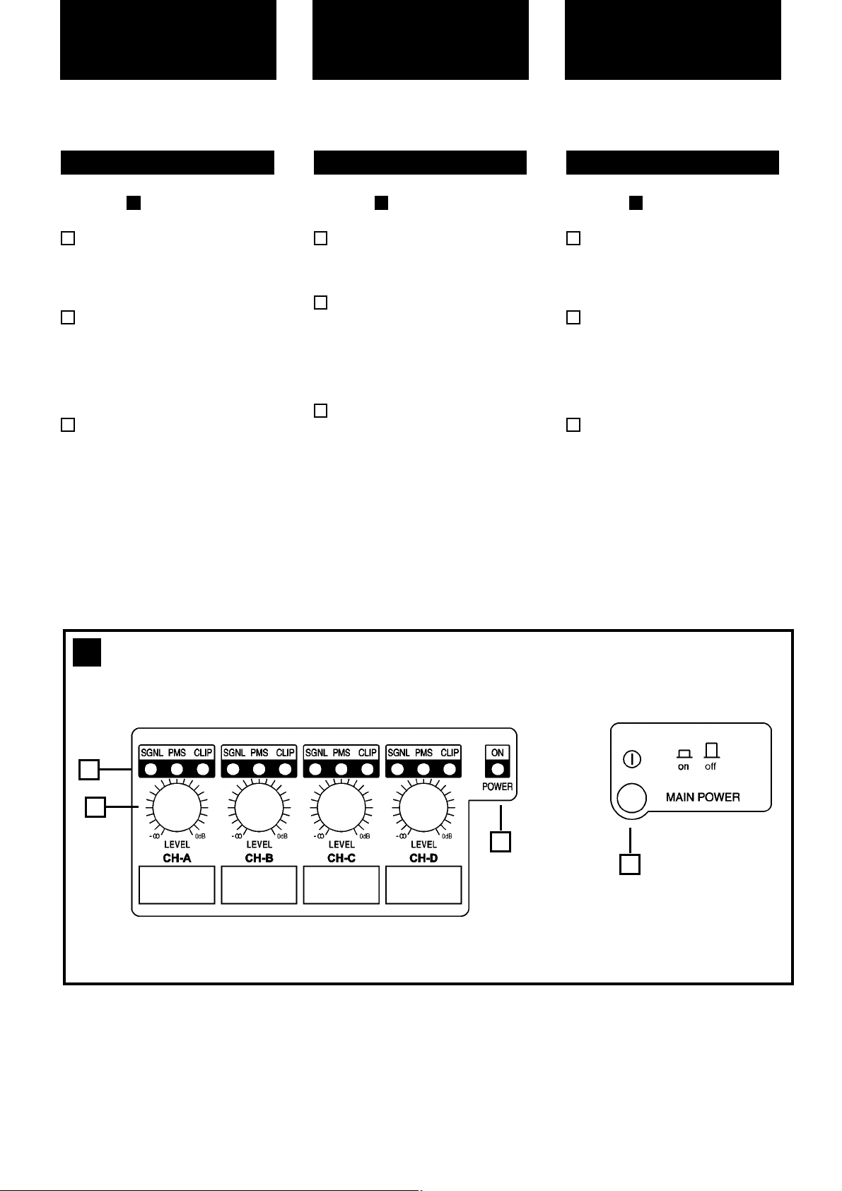
See Figure
Signal attenuation level control
knobs: Permit independent control
of each channel’s attenuation (21
steps).
SIGNAL: This LED indicates pre-
sence of signal at the inputs.
PMS : LED indicating PMS in operation (see page 11).
CLIP: LED indicating Intelligent Clip
Limiter in operation.
Main Power Switch:
Position I: Connects the amplifier's
current feed. (Blue LED on).
Position O disconnects the Power.
3
2
2.1 Front Panel
1
1
Siehe Fig.
Lautstärkeregler: diese ermögli-
chen die Signalstärke am Ausgang
in 21 Stufen zu regeln.
SIGNAL: Wachanzeige des einge-
henden Signals.
PMS : Die LED zeigt an, dass das
PMS in Betrieb ist (siehe Seite 11).
CLIP: Die LED zeigt an, dass der
Intelligent Cliplimiter arbeitet.
Beleuchteter Hauptstromschalter:
Position I: Schaltet die Endstufe ein.
(Blaue LED leuchtet).
Position O Schaltet die Endstufe
aus.
3
2
2.1 Frontplatte
1
1
Ver Figura
Atenuadores de control de nivel:
permite modificar el nivel de la
señal de entrada independientmente
para cada canal, con 21 pasos..
SIGNAL: LED indicador de presen-
cia de señal en la entrada.
PMS: indica que esta actuando el
sistema PMS.
CLIP: indica que esta funcionando
el sistema inteligente anticlip.
Interruptor principal:
Posición I: conecta la alimentación
de corriente del amplificador (el LED
azul luce).
Posición O: desconecta la potencia.
2.1 Panel frontal
1
1
2
3
Front Panel
Page 6
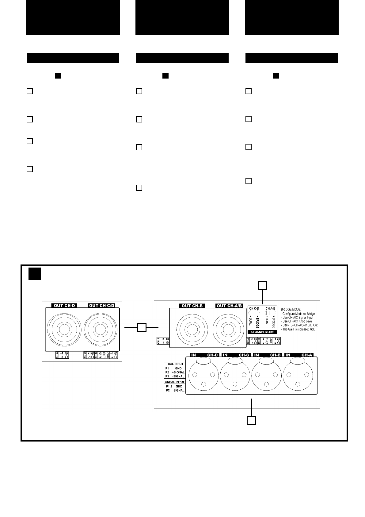
See Figure
Signal Input: Female Neutrik
®
XLR
Connectors for the amplifier’s signal
input.
Speaker connectors: Neutrik
®
Speakon to connect the speakers.
Dual / Bridge Operation Selection
Switch. To control the level in Bridge
mode use the CH-A level knob.
Mains Power Cord: to connect the
amplifier to the mains network. The
colour code is:
Blue: Neutral
Brown: Live, single phase
Yellow-green: Protective Earth
3
2
2.2 Rear Panel
1
2
Siehe Fig.
Eingangssignal: Neutrik
®
-XLR
Buchsen für den Signaleingang der
Endstufe.
Lautsprecheranschluss: Neutrik
Speakonstecker zum Anschluss an
Lautsprecher.
Dual / Bridge: Dieser Schalter
wechselt von Zweikanaloperation zu
Bridge Modus. Bitte benutzen Sie
den Regler des Kanals A um die
Ausgangslautstärke zu kontrollieren.
Mains Power Cord: to connect the
amplifier to the mains network. The
color code is:
Blue: Neutral
Brown: Live, single phase
Yellow-green: Protective Earth
3
2.2 Rückplatte
2
1
2
Lokalisierung der
Funktionen
5
Controls:
Where and What?
Ver Figura
Entrada de señal: conectores
Neutrik XLR hembra para la entrada
de señal al amplificador.
Conectores Speakon: conectores
Neutrik
®
Speakon para la conexión
de altavoces.
Dual / Bridge: interruptor de selec-
ción de operación. Para controlar el
nivel en modo Bridge usa el botón
de nivel del canal A.
Cable de red: para conectar el
amplificador a la red eléctrica. El
código de colores de este es:
Azul: neutro
Marrón: live, fase simple.
Amarillo-verde: protección de tierra.
2.2 Panel Trasero
2
1
2
3
Ubicación y función
de los Controles
2
Rear Panel
2
3
1
Page 7
The Power switch must always be on
the “Off” position before plugging the
amp to a properly earthed mains socket (170-265V AC). The colour code is:
Blue: Neutral
Brown: Live, single phase
Yellow-green: Protective Earth
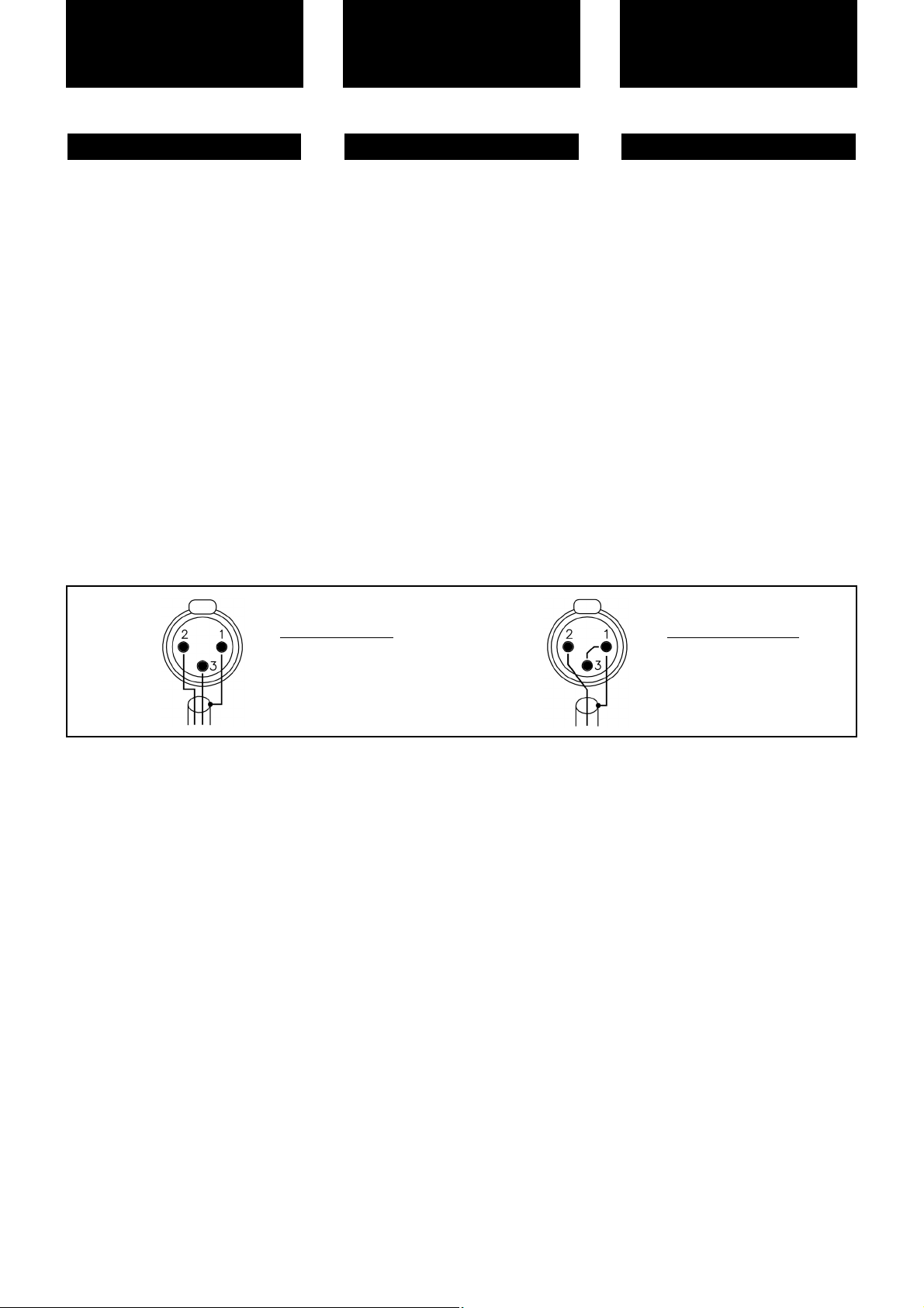
The input signal fed to the amplifier can
be either balanced or un-balanced. The
drawing below describes both ways to
wire an XLR connector for the purpose.
Balanced Signal: Connect pin 1 to
Ground, pin 2 to Signal + (hot) and pin
3 to Signal - (cold).
Unbalanced Signal: Connect Pin 1 to
Ground, pin 2 to Signal and pin 3 to
Ground.
Important!: If a connection is done with
a un-balanced line and pin 3 on the
XLR is not connected to ground, a 6 dB
loss occurs in the line and only a quarter of the amplifier power is produced.
The amplifiers provides, for each channel, a female XLR Connector (Signal
Input) paralleled to a male XLR to daisy
chain several amplifiers with the same
signal line (LINK).
3.1 Connections
Bevor Sie diese Einheit an eine
SHUKO-Steckdose anschließen, schalten Sie den Hautstromschalter aus. The
colour code is:
Blue: Neutral
Brown: Live, single phase
Yellow-green: Protective Earth
Das Eingangssignal kann entweder
symmetrisch oder unsymmetrisch sein.
Für den Anschluss siehe Zeichnung.
Symmetrisches Signal: Die Belegung
der XLR Pins ist wie folgt: 1-Masse, 2Positives Signal (hot), 3-Negatives
Signal (cold).
Asymetrisches Signal: Die Belegung
der XLR Pins ist wie folgt: 1-Masse, 2Signal, 3-Masse.
ACHTUNG! Wenn Sie ein asymetrisches Signal anschließen und Pin 3 nicht
an Masse anschließen, erzeugt dies
einen Verlust von 6dB (1/4 der Leistung
der Endstufe) am Ausgangssignal.
Die Endstufe verfügt über eine parallele
XLR-Buchse für die
Zusammenschaltung mehrerer
Endstufen.
3.1 Anschlüsse
Installation and
Operation
Para proceder al conexionado de la unidad situe siempre el interruptor de alimentacion en la posicion “off”. Conecte
siempre el cable de alimentacion principal (170-265V AC) a una base provista
de toma de tierra. El código de color
es::
Azul: neutro
Marrón: vivo, fase simple.
Amarillo-verde: protección de tierra.
La conexion de la señal de entrada del
amplificador se puede hacer con señal
balanceada o no balanceada. La forma
de realixar la conexion en ambos casos
es la siguiente
Señal Balanceada: conectar el pin 1 a
tierra, el pin 2 a la señal + (hot) y el pin
3 a la señal - (cold) (-).
Señal no Balanceada: conectar pin 1 a
tierra, pin 2 a la señal y pin 3 a tierra.
.
Atencion! : si se de realiza una conexion con señal no balanceada y no se
conecta el pin 3 del XLR a masa, se
producira una perdida de 6 dB en la
señal (¼ de potencia del amplificador).
El amplificador dispone por canal de un
conector XLR hembra para la entrada
de señal y en paralelo con este un
conector XLR macho para la salida de
señal hacia otro amplificador (Link).
Esto permite la union de varios amplificadores con una misma señal de entrada.
3.1 Conexionado
Instalación y
operación
Anschluss und
Inbetriebnahme
Balanced Wiring
1- Ground
2- Signal +
3- Signal -
Unbalanced Wiring
1- Ground
2- Signal
3- Ground
6
Page 8
Installation and
Operation
Instalación y
operación
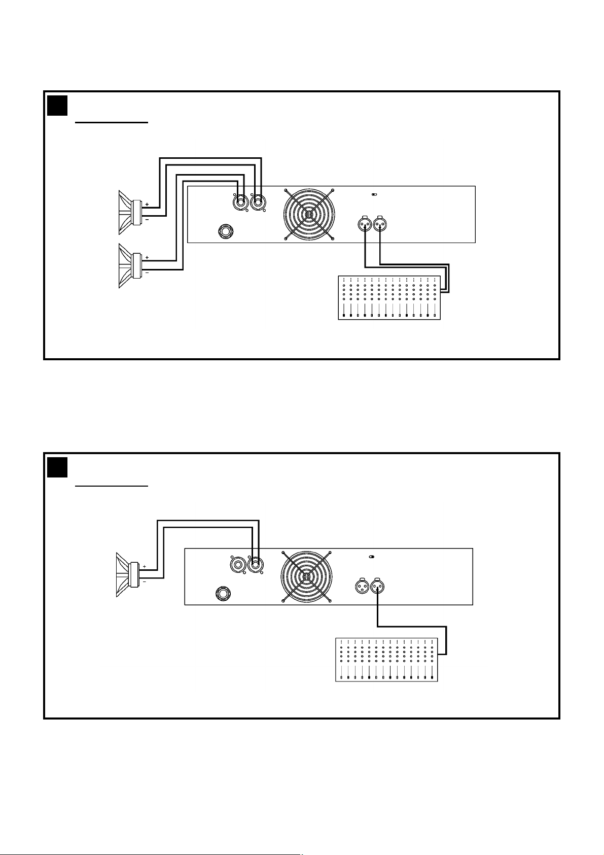
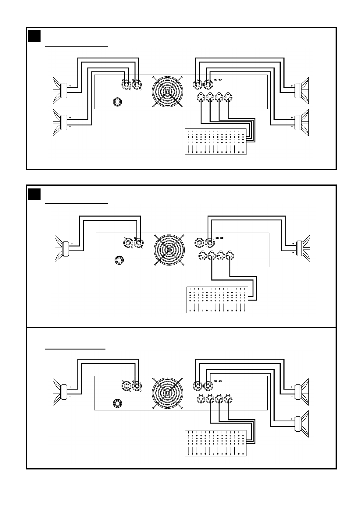
The amplifier can operate on two different configurations: DUAL, or BRIDGE.
The connections for the two modes are
different.
See Figure
- Set the Amplifier Mode to “DUAL”.
- Connect the signal lines to the female
XLR connectors on all channels.
- Connect the speakers’ lines to the corresponding Speakon on the amp
respecting the polarity.
- Use the level control knob on the front
panel to adjust each channel independently.
- Each signalling LED group will show
its corresponding channel status.
See Figure
- Set the configuration mode to
“BRIDGE”
- Connect a signal line to input female
XLR Channel “A” (or Ch-C in 4 channel models).
- Connect the speaker line to the
Channel A Speakon (or Ch-C in 4
channel models) wired to +1 and -2. In
this way pin +1 is positive.
- Use Channel-A (or Ch-C in 4 channel
modes) control knob to adjust the
amp’s output.
- The signalling LED groups will show
the single channel status.
WARNING! The “-“ pins, do not
have to be Ground!
3
3.1.1 DUAL Channel Mode
4
3.1.2 BRIDGE Channel Mode
Existen tres modos de funcionamiento
posibles del amplificador: Dual,
Paralelo, o Puente. Las conexiones en
cada caso son diferentes.
Ver figura
- Coloque el commutador de modo de
funcionamiento, situado en el panel
trasero del amplificador, en la posicion
Dual.
- Conecte las señales de entrada de
ambos canales por sus respectivos
conectores, utilizando para ello los
conectores XLR hembra de cada
canal.
- Conecte los altavoces a los Speakon
respectivas de cada canal respetando
la polaridad.
- Utilice el control de nivel de cada
canal para controlar independientemente los niveles de salida de cada
altavoz.
- Los LEDs de señalizacion indicaran la
situacion independientemente de cada
canal.
Ver figura
- Coloque los commutadores de modo
,situados en el panel trasero del
amplificador, en la posicion Bridge.
- Conecte la señal de entrada al amplificador por el conector de entrada XLR
hembra del Canal A (o canal C en una
etapa de 4 canales).
- Conecte el altavoz al Speakon del
canal A (o canal C en una etapa de 4
canales), cableando al +1 y -2. De
esta forma el pin +1 es positivo.
- Use el botón de control del canal A (o
canal C en las etapas de 4 canales)
para ajustar la salida del amplificador.
¡ATENCIÓN! ¡Los pins “-” no tienen
que ser tierra!
3.1.1 Modo Dual (Stereo)
3
3.1.2 Modo Puente (Bridge)
4
Es gibt zwei Funktionsmöglichkeiten
dieser Endstufe: Dual, und Bridge. Die
Anschlüsse sind in den zwei Fällen
unterschiedlich.
Siehe Fig.
- Stellen Sie den Modusschalter auf die
Modus “Dual”.
- Schließen Sie alle Eingangssignale an
ihre entsprechenden XLR-Buchsen.
- Schließen Sie die Lautsprecher an die
entsprechenden Speakon an, bitte die
Polarität ist beachten.
- Benutzen Sie die Lautstärkeregelung
der entsprechenden Kanäle um den
gewünschten Lautstärkepegel zu erreichen.
- Die LED-Anzeigen geben den Status
der beiden Kanäle an.
Siehe Fig.
- Setzen Sie den Konfigurationsschalter
auf die Modus “BRIDGE”.
- Schließen Sie das Eingangssignal an
die XLR-Buchse “A” an (oder Kanal C
bei 4-Kanalmodellen).
- Schließen Sie den Lautsprecher an
den Kanal “A” Speakon (oder Kanal C
bei 4-Kanalmodellen) verkabelt mit +1
und -2 (+1 ist positiv).
- Benutzen Sie Kanal A (oder Kanal C
bei 4-Kanalmodellen) Potentiometer
für die Regulierung des Endstufenausganges.
- Die LED-Anzeigen werden den Status
des Ausgangkanals angeben.
ACHTUNG! The “-“ pins, do not
have to be Ground!
3
3.1.1 DUAL Kanalmodus
4
3.1.2 Bridge Kanalmodus
7
Anschluss und
Inbetriebnahme
Page 9
3
Dual Channel
2 Ch models
8
4
Bridge Mode
2 Ch models
Page 10
3
Dual Channel
4 Channel models
4 Channel models
4
Bridge Mode
Bridge + Dual Mode
3 Channels Mode
9
Page 11
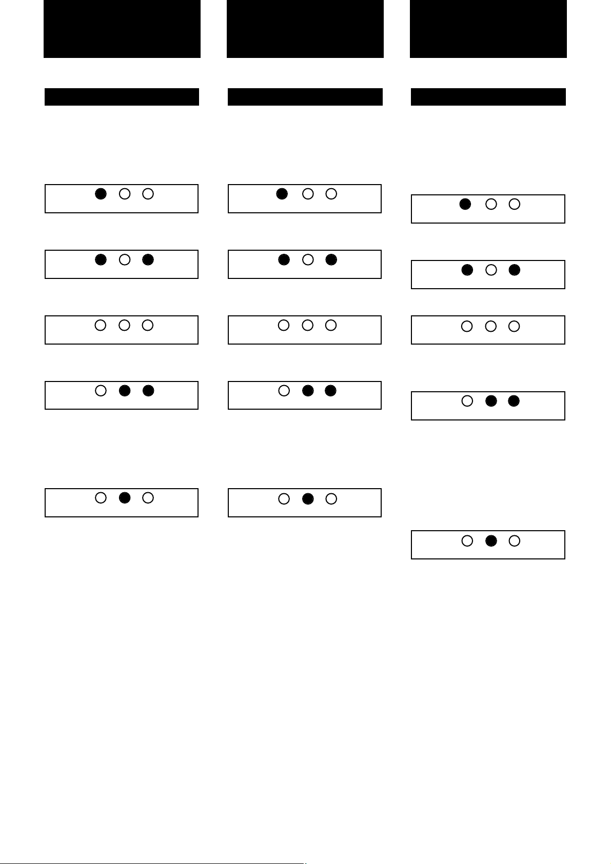
In the event of incorrect connection or
misfunctioning, the amp will activate
one or more of its LED to warn about
the problem.
Correct function: SGNL lights to indicate signal presence.
ICL: The Intelligent Clip Limiter is operating (see page 10).
No Signal: No Input Signal is reaching
the amp.
Overheating: The amplifier has reached the maximum operational temperature. Most common cause is: the normal air flow is blocked, accumulated
dirt, dust or object leaning against the
grill. Check and clean periodically.
PMS: Several causes can trigger this
LED, most common are:
- The amplifier is in power-on sequence,
where output is inhibited until the amp
circuits are ready to operate.
- The internal temperatures rise to near
thermal shutdown point due to unfavourable operating conditions.
- Excessive current consumption.
3.2 Troubleshooting
Sollte sich eine Fehlfunktion ergeben,
wird diese durch die LED-Anzeigen auf
der Frontplatte angezeigt. Es gibt folgende Möglichkeiten:
Korrektes Arbeiten: SGNL leuchtet
wenn Eingangssignal vorhanden ist.
ICL: Der Intelligent Clip Limiter ist in
Betrieb (Siehe Seite 10).
Kein Eingangssignal: Kein
Eingangssignal vorhanden.
Überhitzung: Die Endstufe hat die
maximale Arbeitstemperatur erreicht.
Die häufigste Ursache ist
Verschmutzung oder Blockierung der
Luftein- und Austritte. Es ist ratsam
diese regelmäßig zu säubern.
PMS: Mehrere Ursachen können dieses
LED auslösen, die häufigsten sind:
- Die Endstufe befindet sich im
Anschaltevorgang, das
Ausgangssignal wird so lange
gehemmt bis die Enstufe voll funktionsbereit ist.
- Die Innentemperatur steigt aufgrund
ungünstiger Arbeitsbedingungen nahe
des Grenzwertes bei dem die automatische Ausschaltefunktion aktiviert wird
um eine Überhitzung des Systems zu
vermeiden.
- Überhöhter Netzstromverbrauch
.
3.2 Problemlösung
Installation and
Operation
Si se produce alguna anomalia en la
Instalación o durante el funcionamiento
del amplificador, este indicara mediante
los LEDs de la caratula la posible causa
de la misma. Las posibles situaciones
indicadas son las siguientes:
Funcionamiento correcto: SGNL luce
para indicar presencia de señal.
ICL: situacion de CLIP en la salida.
Ausencia de señal: no existe señal de
entrada al amplificador.
SobreTemperatura: actuacion de las
protecciones del amplificador por exceso de temperatura. Esto puede ser
devido a la obstruccion de las tomas de
aire situadas en la parte trasera de la
unidad. Es conveniente limpiar de vez
en cuando las rejilla de entrada de aire
de ventilacion.
PMS: distintas causas pueden hacer
lucir este LED. Las mas comunes son::
- El amplificador esta temporizando el
encendido, y las salidas son inhibidas
hasta que todo esta listo para funcionar.
- La temperatura interna del amplificador esta próxima a su punto de protección debida a condiciones de uso
inadecuadas.
- Consumo de corriente excesivo para
la fuente de alimentación.
3.2 Problemas y Soluciones
Instalación
y operación
10
Anschluss und
Inbetriebnahme
CLIP
CLIP
CLIP
CLIP
CLIP
CLIP
CLIP
CLIP
CLIP
CLIP
CLIP
CLIP
CLIP
CLIP
CLIP
PMSSGNL
PMSSGNL
PMSSGNL
PMSSGNL
PMSSGNL
PMSSGNL
PMSSGNL
PMSSGNL
PMSSGNL
PMSSGNL
PMSSGNL
PMSSGNL
PMSSGNL
PMSSGNL
PMSSGNL
Page 12

This is a complete set of protections that
monitors the main amp parameters (load
status, signal input, temperature, current,
etc.) in order to draw from the power supply only the precise amount of current
required to maintain safe operation during
hazardous or extreme working conditions.
This system controls the amount of power
that the amp delivers under three basic
circumstances:
1.- The power-on sequence, where output
is inhibited until the amp circuits are ready
to operate. This routine is repeated at
every restart, not just when the power
switch is activated.
2.- When internal temperatures rise to
near thermal shutdown point due to
unfavourable operating conditions. Here
the system takes control, restricting current so as to maintain operational continuity at the precise power level which the
amp is capable of withstanding at that particular moment.
3.- Excessive current consumption. This
event only occurs either under laboratory
conditions (long term sinusoidal signal
testing with dummy loads) or, for example,
in field applications in conditions of prolonged acoustic howl-round. Here PMS
takes control to avoid any damage to the
speakers and to prevent the mains breaker from tripping or the fuses blowing.
The RAM Audio ICL2 is an anticlip system
to avoid speaker failure and provide more
acceptable sound quality even when clipping occurs. With the ICL2 system you
don't lose the music “punch” but the
speakers are kept under control.
SOA Sentry protection effectively limiting
the power that the amp could deliver into
an incorrect load or to a direct short-circuit. This avoids power transistor failure.
PMS™ - Power Management System
SSP™ - SOA Sentry Protection
ICL2™ - Intelligent Clip Limiter
Vollständiges Set von Schutzfunktionen
das die wichtigsten Endstufenparameter
überwacht (Auslastung, Signaleingang,
Temperatur und Stomstärke) um vom
Netzanschluss nur die Menge Strom zu
beziehen, die für den betriebssicheren
Arbeitsablauf notwendig ist
Dieses System reguliert die von der
Endstufe abgegebenen Leistung in 3
Fällen:
1.- Anschaltevorgang: Der Ausgang wird
gehemmt bis die Endstufe voll funktionsbereit ist. Dieser Vorgang wiederholt sich
bei jedem Neustart, nicht nur wenn der
Leistungsschalter aktiviert wurde.
2.- Wenn die Innentemperatur aufgrund
ungünstiger Arbeitsbedingungen nahe des
Grenzwertes steigt, bei dem die automatische Ausschaltefunktion aktiviert würde,
um eine Überhitzung des Systems zu vermeiden. In diesem Fall übernimmt das
System die Kontrolle und reduziert die
Stromzufuhr auf ein Niveau, dass die
Endstufe in dieser Situation aushalten
kann.
3.- Überhöhter Stromverbrauch: Diese
Situation stellt sich ausschließlich unter
Laborbedingungen ein (in sinusförmigen
Langzeitsignaltests mit Dummylasten oder
in langanhaltenden akustischen Feedback
Bedingungen. Hier greift das PMS System
ein um eine Schädigung der Lautsprecher
zu vermeiden und um zu verhindern dass
der Hauptunterbrecher ausgelöst wird oder
die elektrischen Sicherungen durchbrennen.
Das RAM Audio ICL2 ist ein Anticlipsystem
das das Versagen der Lautsprecher vermeidet und auch wenn Clipping auftritt
noch eine bessere Tonqualität gewährleistet. Mit dem ICL2 System verlieren Sie
den “Punch” nicht, und der Lautsprecher
arbeitet kontrolliert.
SOA Die Leistung, die die Endstufe an
inkorrekte Lasten oder an einen
Kurzschluss abgeben könnte wird wirksam
limitiert. Dies verhindert die Zerstörung der
Leistungstransistoren.
SSP™ - SOA Sentry Protection
PMS™ - Power Management System
ICL2™ - Intelligent Clip Limiter
Protection Systems
Este es un completo set de protecciones
que monitoriza los parámetros principales
del amplificador (estado de la carga, señal
de entrada, temperatura, corriente, etc.)
para así sacar de la fuente de alimentación solo la cantidad de corriente requerida para mantener una operación segura
durante condiciones extremas de trabajo.
Este sistema controla la cantidad de
potencia que el amplificador entrega bajo
tres circunstancias básicas:
1.- La secuencia de encendido, donde la
salida es inhibida hasta que los circuitos
del amplificador están preparados para
operar.
2.- Cuando la temperatura interna llega
casi al punto de bloqueo térmico debido a
condiciones de operación desfavorables.
Aquí el sistema toma el control restringiendo la corriente para mantener la continuidad operacional al nivel de potencia preciso en el que el amplificador es capaz de
resistir este particular momento.
3.- Consumo de corriente excesivo. Este
caso solo ocurre o en condiciones de
laboratorio (test con señal sinoidal durante
largo tiempo con cargas ficticias) o, por
ejemplo, en aplicaciones de campo en
condiciones de re-alimentación acústica.
Aquí el PMS toma el control para evitar
cualquier daño en los altavoces y prevenir
que el magnetotérmico salte o los fusibles
se fundan .
El ICL2 es un sistema anticlip que evita
daño en el altavoz y provee de una calidad de sonido más aceptable incluso
cuando el clip está ocurriendo. Con el sistema ICL2 no puerdes el “punch” de la
música pero el altavoz es mantenido bajo
control.
El sistema SOA Sentry Protection limita de
forma efectiva la potencia que el amplificador puede entregar frente a una carga
incorrecta o a un corto-circuito. Este evita
fallos en los transistores de potencia.
SSP™ - Protección SOA Sentry
PMS™ - Sistema manejo de potencia
ICL2™ - Limitador de clip inteligente
Sistemas de
Protección
11
Schutzschaltungs-
systeme
Page 13

4.2 Data 4.2 Datos técnicos4.2 Technische Daten
Technical
Specifications
Especificaciones
técnicas
Technische
Spezifikationen
12
Z-210 Z-215 Z-220 Z-236 Z-420 Z-430 Z-440 Z-4100
Output Power*
@ 2W 2x 500W 2x 750W 2x 1000W 2x 1800W 4x 500W 4x 750W 4x 1000W 4x 2500W
@ 4W 2x 400W 2x 700W 2x 1000W 2x 1750W 4x 400W 4x 700W 4x 1000W 4x 2500W
@ 8W 2x 240W 2x 450W 2x 650W 2x 950W 4x 220W 4x 450W 4x 630W 4x 1400W
Bridge @ 4W 1000W 1500W 2000W 3600W 2x 1000W 2x 1500W 2x 2000W 2x 5000W
Bridge @ 8W 800W 1400W 2000W 3500W 2x 800W 2x 1400W 2x 2000W 2x 5000W
High Z
70Vrms/100Vpeak 1x 900W - 2x 700W - 2x 900W - 4x 700W 100Vrms/140Vpeak - 1x 1400W - - - 2x 1400W - Frequency Response
Power Bandwidth ±0.25dB 20Hz-20kHz
Phase Response
@ 1 watt 20Hz-20kHz ±15 deg
Total Harmonic Distortion
20Hz-20kHz <0.05%
Intermodulation Distortion
SMPTE <0.05%
Damping Factor
20-500Hz @8W >500
Crosstalk
20Hz-1kHz >75dB
Voltage Gain 35dB 26-40dB
Sensitivity
Rated Power 0.8 V 1.1 V 1.3 V 1.6 V 0.8 V 1.1 V 1.3 V 5.3V-1.1V
Signal-to-Noise Ratio
20Hz-20kHz 101dBA 103dBA 104dBA 105dBA 101dBA 103dBA 104dBA 107.5dBA
Required AC Mains
Operating Voltage (50Hz-60Hz) 170V-265V AC
Power On Idling (@230V) 0.5 A 0.5 A 0.5 A 0.5 A 0.5 A 0.5 A 0.5 A 0.5 A
1/8 Rated Power (@4 ohm) 3.5 A 4 A 5 A 10 A 7 A 8 A 10 A 16 A
Dimensions
W x H x D (mm) 483x88.9x254 483x88.9x274
W x H x D (inches) 19x3.5x10 19x3.5x10.8
Weight
Net (Kg-Lbs) 5-11 5-11 6.5-14.3 6.5-14.3 6.5-14.3 6.5-14.3 6.5-14.3 7-15.4
Protections
Soft-start, Turn-on/off transients, Over-heating, DC, RF, Short-circuit, Open or mismatched loads, ICL
™
, PMS™ and SSP™
*All channels driven, full bandwidth P.N. 12dB C.F.
Page 14

Manufactured in the EEC by C.E. Studio-2 s.l.
Pol. Ind. La Figuera - C/Rosa de Luxemburgo, nº 34
46970 Alaquas - Valencia - SPAIN
Phone: +34 96 127 30 54 Fax: +34 96 127 30 56
http://www.ramaudio.com e-mail: [email protected]
 Loading...