

RAM V-6000, V-9000, V-12000, V-9004, V-9044 Operation Manual
...
OPERATION MANUAL
NOTICE D’EMPLOI
BEDIENUNGSANLEITUNG
P-6546-564
QXPDQXDoc
4/11
© 2011 by C.E. Studio-2 s.l. - Spain (EEC)
http://www.ramaudio.com
e-mail: support@ramaudio.com
Professional Power Amplifiers
V
Series
6000-9000-12000
9004-9044-12004-12044
WARNING:
To avoid fire or electrocution risk do not
expose the unit to rain or moisture.
To avoid electric shock, do not open the
unit. No user serviciable parts inside. In
the case of disfunction, have the unit
checked by qualified agents.
Class I device.
IMPORTANT:
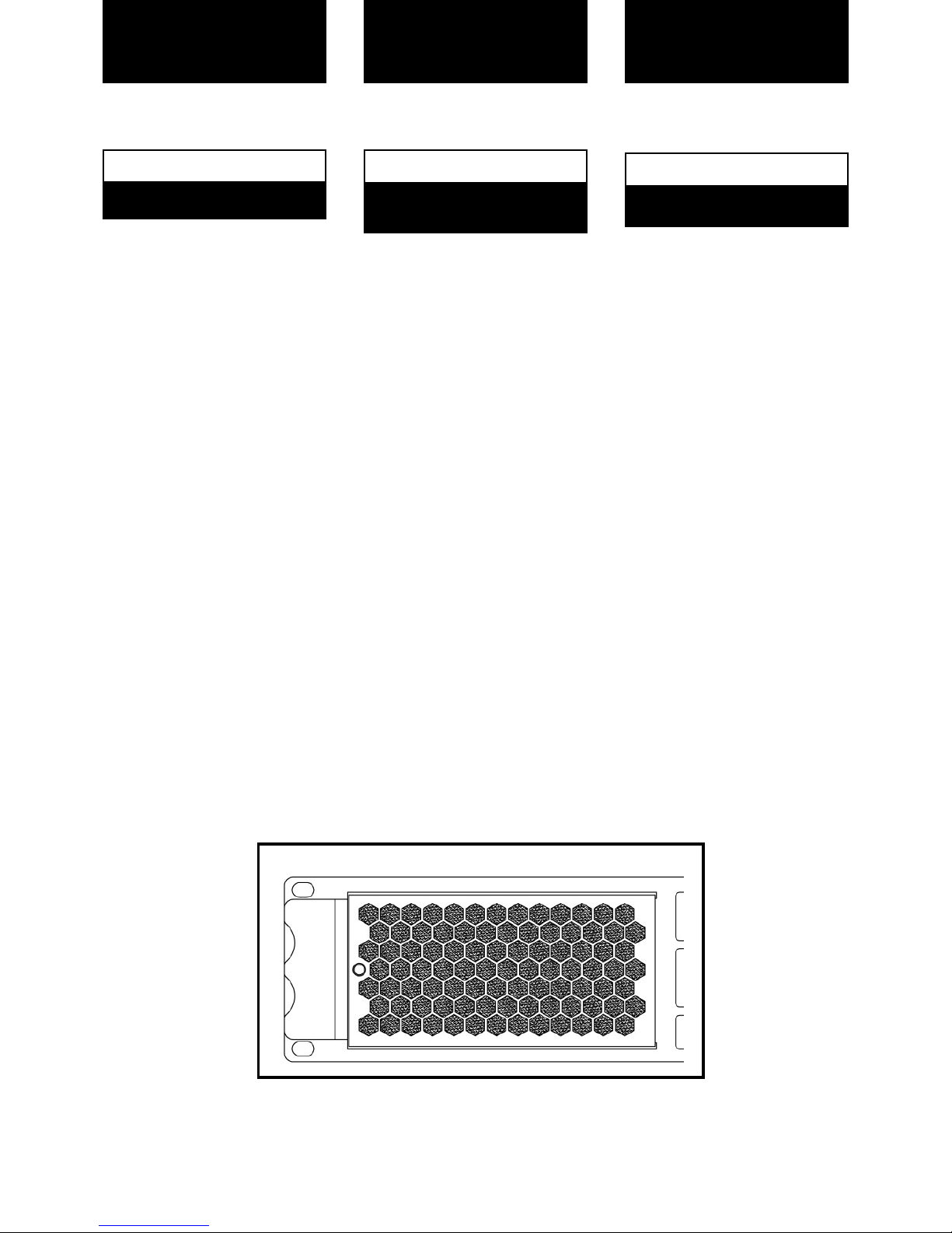
Clean the front panel filters regularly.
Extract the filters removing the front
panel grid unscrewing the thumbscreews placed at the sides of the grid.
Clean the filters using water and detergent. Place the grid filter introducing
first the internal side and screwing the
thumbscrew.
SAFETY
PRECAUTIONS
AVERTISSEMENTS
SICHERHEITSHINWEISE
CAUTION
RISK OF ELECTRIC SHOCK
DO NOT OPEN
ACHTUNG!:
Um Brand oder elektrische Schläge zu
vermeiden, darf diese Einheit
keiner starken Luftfeuchtigkeit oder
Regen ausgesetzt werden.
Um elektrische Schläge zu vermeiden,
öffnen Sie diese Einheit nicht. Bei
Reparaturbedarf wenden Sie sich an
qualifiziertes Personal.
Es handelt sich um ein Gerät der
Klasse I.
IMPORTANT:
Clean the front panel filters regularly.
Extract the filters removing the front
panel grid unscrewing the thumbscreews placed at the sides of the grid.
Clean the filters using water and detergent. Place the grid filter introducing
first the internal side and screwing the
thumbscrew.
1
VORSICHT
GEFAHR EINES
ELEKTRISCHEN SCHLAGES.
NICHT ÖFFNEN!
RÈGLES DE SÉCURITÉ:
Pour écarter tout risque d’incendie ou
d’électrocution, ne pas exposer l’appareil à la pluie ni à l’humidité.
Afin d’éviter tout risque, ne pas ouvrir
l’appareil. Ne confier l’entretien de l’appareil qu’à du personnel technique qualifié et agréé.
Appareil de Classe I.
IMPORTANT:
Clean the front panel filters regularly.
Extract the filters removing the front
panel grid unscrewing the thumbscreews placed at the sides of the grid.
Clean the filters using water and detergent. Place the grid filter introducing
first the internal side and screwing the
thumbscrew.
ATTENTION
RISQUE DE CHOC ÉLECTRIQUE
NE PAS OUVRIR
Grid Filter Detail

0 Safety Precautions
1 General Information
1.1 Introduction
1.2 Main Characteristics
2 Controls: Where and What?
2.1 Front Panel
2.2 Rear Panel
3 Installation and Operation
3.1 Connections
3.1.1 Dual Channel Mode
3.1.2 Link Channel Mode
3.1.3 Bridge Channel Mode
3.2 Configuration
3.3 Troubleshooting
4 Technical Specifications
4.1 Protection Systems
4.2 Data
©2011 by C.E. Studio-2 s.l.
Pol.Ind. La Figuera
C/Rosa de Luxemburgo nº34
46970 Alaquas - Valencia - SPAIN
Phone: +34 96 127 30 54
Fax: +34 96 127 30 56
http://www.ramaudio.com
e-mail: support@ramaudio.com
P-5435-634 QXPDQXDoc 4/11
RAM Audio
®
, PMS
™
, SSP™, ICL™,
FCM
™
and QuantaPulse™are registered trademarks of C.E. Studio-2 s.l..
All other names are trademarks of their
respective companies.
0 Sicherheitshinweise
1 Allgemeine Anweisungen
1.1 Einleitung
1.2 Allgemeine Eigenschaften
2 Lokalisierung der Funktionen
2.1 Frontplatte
2.2 Rückplatte
3 Anschluss- und Inbetriebnahme
3.1 Anschlüsse
3.1.1 Dual Kanalmodus
3.1.2 Link Kanalmodus
3.1.3 Bridge Kanalmodus
3.2 Konfiguration
3.3 Problemlösung
4 Technische Spezifikationen
4.1 Schutzschaltungssysteme
4.2 Technische Daten
INHALTSVERZEICHNIS
INDEX
0 Avertissements
1 Informations Générales
1.1 Introduction
1.2 Caractéristiques générales
2 Commandes et fonctions
2.1 Panneau avant
2.2 Panneau arrière
3 Installation et mise en route
3.1 Branchements
3.1.1 Mode DUAL
3.1.2 Mode LINK
3.1.3 Mode BRIDGE
3.2 Configuration
3.3 Dysfonctionnements éventuels
et dépannage.
4 Spécifications
4.1 Systèmes de Protection
4.2 Données téchniques
TABLE DES
MATIÈRES
2

The V Series devices feature two or four
channel models, ready for rough handling in the touring world. For this purpose, V Series amps implement oversized high efficiency regulated power
supply with PFC front end to deliver
their full performances independently of
mains status. This together with oversized high efficiency audio power
stage, forced front to back cooling
through a component-free path with
removable front panel dust filters,
improved rugged mechanical design
with even weight distribution, full digital
control from LCD display on the front
panel... Resulting in: just power, reliability and robustness for your touring
gigs!
• PFC QuantaPulse™Regulated Dual
SMPS
• Digital Control with extra large LCD
display user interface
• Channel Temperature and Output
Level Monitor in the LCD
• USB port for firmware update and
DSP control
• 25 position Gain, Bridge mode, Input
Links and ICL, front panel configurable
• Digital Potentiometers with Encoder
control
• RAM Audio Power Management
System
• Hi Efficiency, Heavy Duty Audio Power
section for extreme use
• Easily removable front panel dust filters
• Industry standard Neutrik
®
XLR and
Speakon
®
connectors
• Optional low latency 24bits 96kHz
high performance DSP with post-DSP
signal links and Ethernet control. It
features up to 70 meters input delay.
•
Optional EtheRAM II Ethernet monitor
and control system
•
Optional EtherSound™/CobraNet™
audio transport and AES/EBU Digital
input
1.2 Main Characteristics
1.1 Introduction
General Information
Informations
Générales
Allgemeine
Anweisungen
3
Lokalisierung der
Funktionen
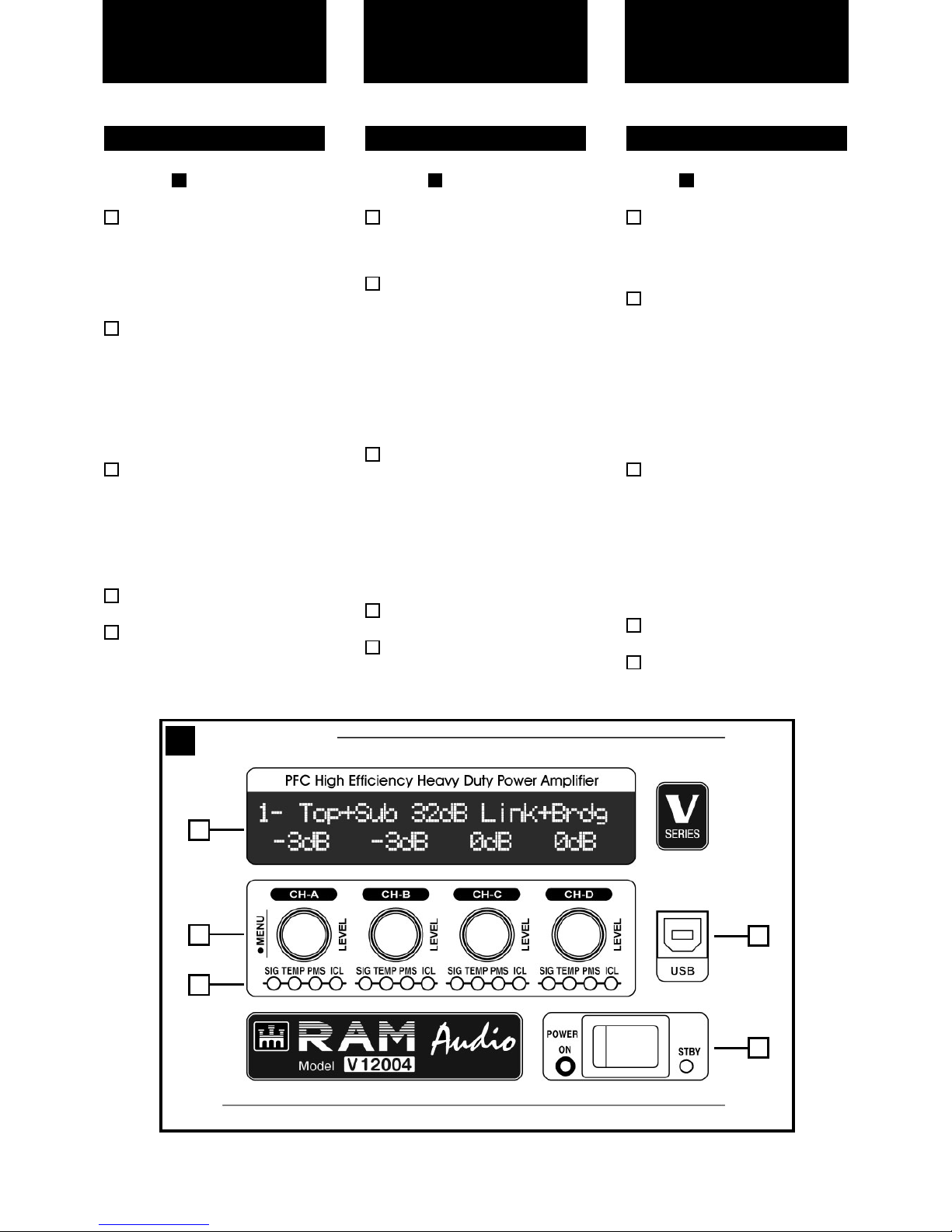
See Figure
Configuration and signal attenuation level control knobs: Permit
independent control of each channel’s attenuation and change the
amplifier configuration. See page
10.
SIGNAL: This LED indicates presence of signal at the inputs.
TEMP: This LED shows temperature protection is active.
PMS: LED indicating PMS in operation (see page 13)
ICL: LED indicating Intelligent Clip
Limiter in operation (see page 13).
Main Power Switch:
Position I: Connects the amplifier's
current feed. (Blue LED on).
Position O disconnects the Power.
Position II (optional): Stand-by
Mode. The Amp's Power is activated
remotely via Ethernet. (Amber LED).
Display: See page 10.
USB Connector for firmware
upgrade and optional DSP control.
5
4
3
2
2.1 Front Panel
1
1
Siehe Fig.
Lautstärkeregler: diese ermögli-
chen die Signalstärke am Ausgang.
siehe Seite 10.
SIGNAL: Wachanzeige des eingehenden Signals.
TEMP: LED-Anzeige leuchtet wenn
der Schutz vor Überwärmung eingeschaltet ist.
PMS: Die LED zeigt an, dass das
PMS in Betrieb ist (siehe Seite 13)
ICL: Die LED zeigt an, dass der
Intelligent Cliplimiter arbeitet (siehe
Seite 13).
Beleuchteter Hauptstromschalter:
Position I: Schaltet die Endstufe ein.
(Blaue LED leuchtet).
Position O Schaltet die Endstufe
aus.
Position II (optional): Stand-by
Modus. Die Endstufe kann über
Ethernet eingeschaltet werden.
(Gelbe LED).
Display: siehe Seite 10.
USB Connector for firmware upgra-
de and optional DSP control.
5
4
3
2
2.1 Frontplatte
1
1
Controls:
Where and What?
Voir Fig.
Configuration et Atténuateurs de
signal d’entrée crantés: réglage
du niveau d’entrée indépendant sur
chaque canal. Voir page 10.
SIGNAL: indique la présence de
signaux d’entrée.
TEMP: signalisation par LED de
temperature excessive.
PMS: signalisation par LED de le
fonctionnement de le
système PMS
(voir page 13).
ICL: signalisation par LED de le
fonctionnement de le
système ICL
(voir page 13).
Power:
Position I: Connecte l'appareil au
courant, (LED Bleue allumée).
Position O: Interruption de la mise
sous tension.
Position II (optional): Mode stand-by,
la mise sous tension s'effectue a
distance via Ethernet, (LED Orange
allumée).
Display: voir page 10.
USB Connector for firmware upgra-
de and optional DSP control.
5
4
3
2
2.1 Panneau Avant
1
1
Commandes et
Fonctions
4
1
Front Panel
1
4
2
3
5
 Loading...