

Page 1
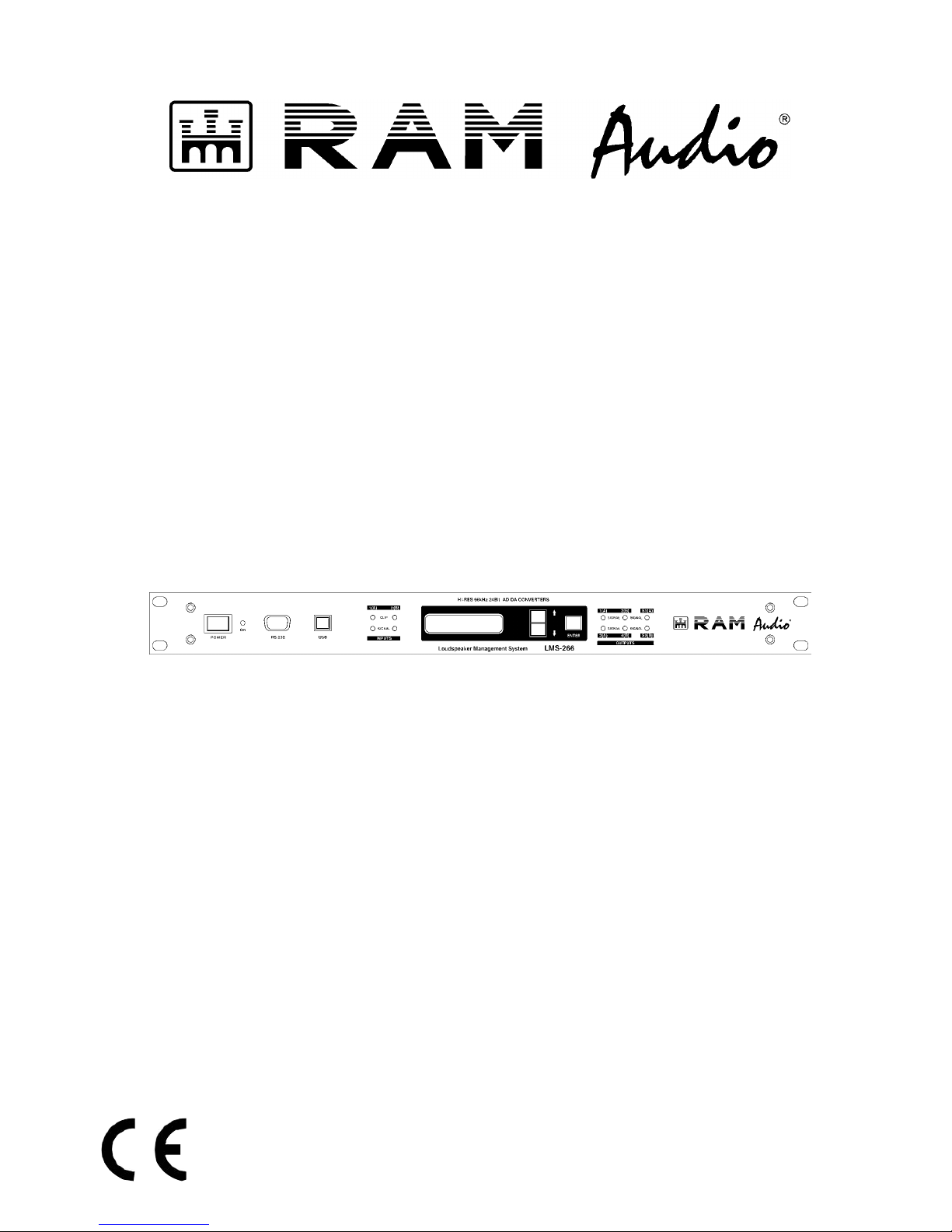
HARDWARE MANUAL
P-98754-005
QXPLMSDoc
11/05
© 2005 by C.E. Studio-2 s.l. - Spain (EEC)
http://www.ramaudio.com
e-mail: [email protected]
LMS 266 / LMS 221 Digital Controllers
Loudspeaker Management System
Page 2

RAM Audio LMS 266 / LMS 221 Digital Controller – Hardware Manual
1
CONTENTS
1. INTRODUCTION
Description LMS 221/ LMS 266
4
Description front panel 5
Description rear panel
6
2. INSTALLATION AND ASSEMBLY
Connectors and connections
7
Dimensions 8
How to connect 8
3. PROCESS DIAGRAM
Block diagrams LMS 221/ LMS 266
9
4. OPERATION
Use procedures
11
Display and edition elements
12
Program menu 13
Menu hierarchy
14
1.CONFIGURATION
15
1.1. Out delay
15
1.2. Gain 16
1.3. Output POL
17
1.4. Temperature
18
1.5. Password 19
1.6. Protect
20
2. INFORMATION
21
2.1. Prot. Mem 21
2.2. Test LCD
21
2.3. Version 21
3. COMMUNICATION
22
3.1. Prepare Clon 22
3.2. Clone 23
3.3. Send Memory
24
3.4. Receive Memory 25
5. TECHNICAL SPECIFICATIONS
26
6. PROBLEMS SOLUTION
27
7. GUARANTEE
28
Page 3

RAM Audio LMS 266 / LMS 221 Digital Controller – Hardware Manual
2
WELCOME
You have just started working with the digital processors RAM AUDIO LMS Series.
Before starting to use the processor we recommend reading this manual carefully; you will find
instructions for use, programming examples and practical advices, which will be of great help to
you.
The digital processors RAM AUDIO include the latest digital technology advances. With a
maximum of precision and numerous features they are designed to meet the best professionals´
highest expectations in the sound environment.
If you wish to change some configuration parameters or create new configurations for your
sound system, we recommend to carefully read this manual and the manual for the software of
LMS processors.
We hope that LMS 221 / LMS 266 will meet your expectations as a technician and user and will
make your work easier.
Welcome to RAM AUDIO!
(www.ramaudio.com)
Page 4
RAM Audio LMS 266 / LMS 221 Digital Controller – Hardware Manual
3
IMPORTANT INFORMATION ON SECURITY
The CE mark on the processor LMS 221 / LMS 266 indicates that it is verified and
tested to entirely fulfil the European and international regulations concerning
electromagnetic compatibility and electric safety.
Radiated emissions: EN55013-1 (1996)
RF Immunity: EN55103-2 (1996)
Electric Safety: EN60065 (1993)
IEC65 (1985) and amendments 1, 2 and 3
This product fulfils also the specifications of the following safety directives:
Directive of low voltage: 73/23/EEC
Directives EMC: 89/336/EEC and amendment 93/68/EEC
This product is totally designed and manufactured in the European Union.
CAUTION
RISK OF ELECTRIC SHOCK
DO NOT OPEN
These symbols are internationally accepted and warn of potential damages caused by the
improper manipulation of electric appliances.
The beam pointing down inside an equilateral triangle warns of dangerous voltage existing
inside the appliance. The exclamation mark inside an equilateral triangle reminds the user to
pay attention to the safety indications shown in this manual.
Some of the indications which this sign refers to are:
Do not expose the processor to dust or humidity.
Do not open the processor’s lid.
To avoid damages caused by electric shock, do not manipulate interior
elements.
Only use appropriate and intact power cables.
In case of any strange performance, always contact the technical service.
Unpacking the processor LMS 221 / LMS 266
Before unpacking your processor, make sure that the packing is neither damaged nor
deformed. In case of important anomalies, please contact your transport agency. After
unpacking the product and checking the equipment’s perfect working order, please keep the
original packing just in case you have to return the processor to the distributor.
Page 5

RAM Audio LMS 266 / LMS 221 Digital Controller – Hardware Manual
4
1.- INTRODUCTION
With its 60 user’s memories LMS 221 / LMS 266 will allow you to configure your settings for
your systems. LMS 221 / LMS 266 disposes of the software LMS 221 / LMS 226 Control
(under Windows 95/98/ME/NT/2000/Me/XP), which makes it possible to modify all the
parameters of the system. We recommend to carefully reading the manual of the software
before making any configurations. You will find the explanation of the working order and all the
possibilities of the processor LMS 221 / LMS 266 explained in this manual.
LMS 221 / LMS 266 offers all the necessary elements for the installation to the sound
technician.
- 2 inputs / 6 outputs (2 inputs / 3 outputs for LMS 221).
- Independent output delays.
- 34 EQ filters absolutely configurable (17 for LMS 221).
- 6 Crossovers up to 24 dB/Oct (3 for LMS 221).
- Gains, mutes and phase inversion per way.
- Dynamic control with Limiter/ compressor and noise gate.
etc...
all this together with the best electronic components to guarantee as clearest and most accurate
sound possible with all the necessary protections for your system.
Processor Description LMS 221 / LMS 266
LMS 221 / LMS 266 audio digital controller is an audio digital processor, configurable by the
user, with two inputs / three outputs and two inputs / 6 outputs respectively, designed to cover
uses like:
LMS 221:
- Full range stereo processor plus sub.
- 2 way stereo processor plus mono sub output.
- 3 way mono processor complete for installations (High-Mid-Low).
- Stereo paragraphic equalizer.
- Stereo Compressor / Limiter
- Etc.
LMS 266:
- 3 way stereo processor (High-Mid-Low).
- 4 way mono processor plus 2 sub outputs.
- Etc.
Page 6
RAM Audio LMS 266 / LMS 221 Digital Controller – Hardware Manual
5
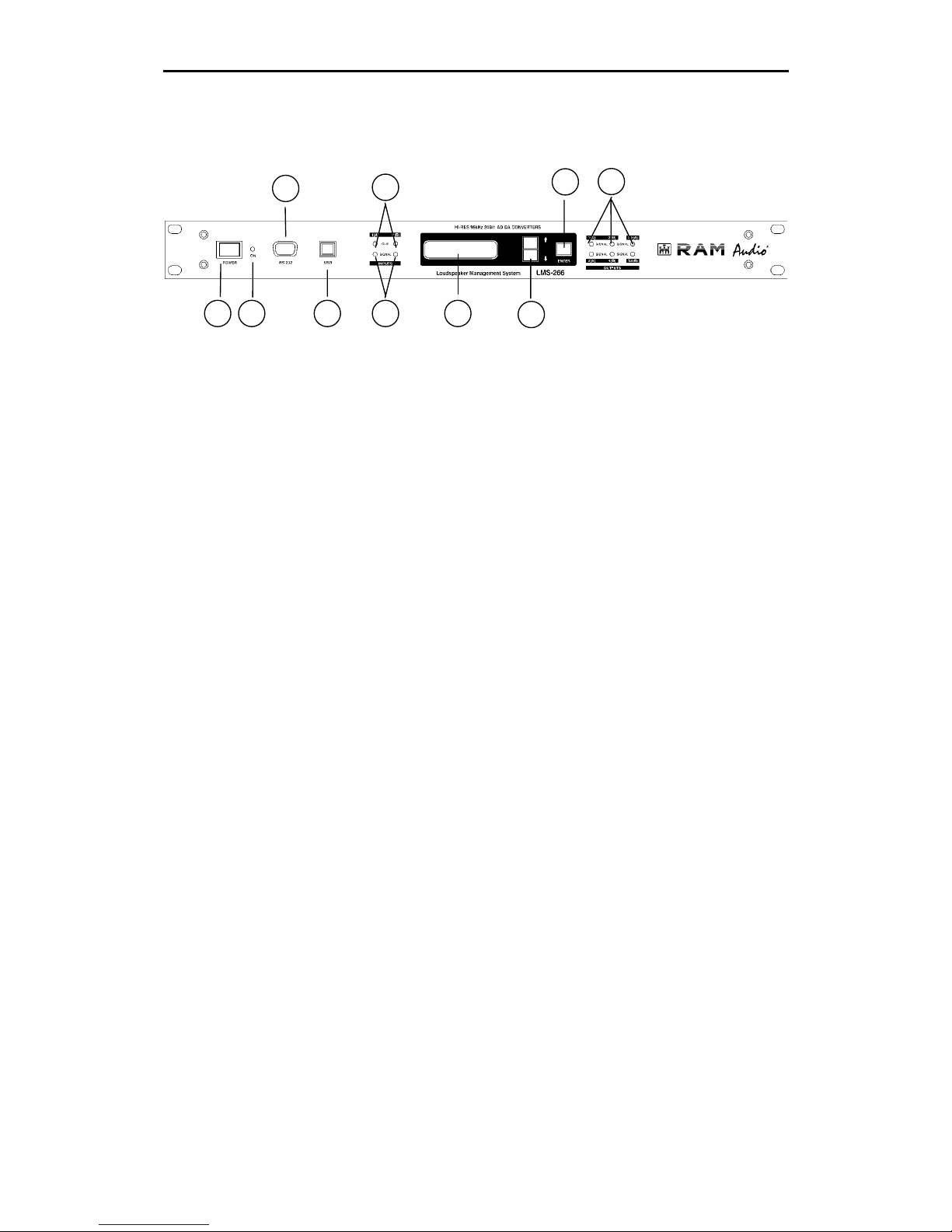
Front Panel Description LMS 266
1.- MAIN POWER SWITCH
Connects and interrupts the processor’s current feed.
2.- SWITCH ON INDICATOR LED
Indicates that the processor is switched on.
3.- RS-232C CONNECTOR
Male Sub-D connector of 9 contacts for communication with PC.
4.- USB CONNECTOR
Type B female USB connector for communication with PC.
5.- INPUT SIGNAL INDICATOR LEDS
Indicate presence of signal at the inputs.
6.- INPUT CLIP INDICATOR LEDS
These LEDs when illuminated indicate that the corresponding
channel is clipping the processor’s input, producing a trim and
distortion of the signal. These LEDs should never illuminate.
7.- DISPLAY
Shows the menus, information on working order as well as diverse
modifiable parameters by the user.
8.- MENU KEYS
Permit to move up and down in the menus and to increase and
decrease different parameters.
9.- ENTER KEY
Allows access to menus and submenus and confirms actions.
10.- OUTPUT SIGNAL INDICATOR LEDS
Show the presence of signal in the outputs.
1
237
10
8
6
954
Page 7
RAM Audio LMS 266 / LMS 221 Digital Controller – Hardware Manual
6
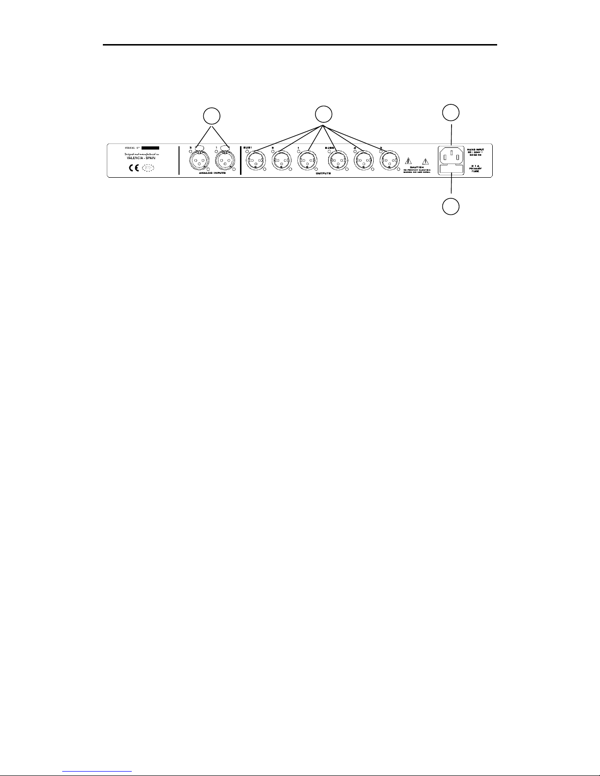
Rear Panel Description LMS 266
11.- SIGNAL INPUTS
Female XLR connectors of 3 contacts.
12.- SIGNAL OUTPUTS
Male XLR connectors of 3 contacts.
13.- IEC POWER SUPPLY CONNECTOR
The mains cable is supplied with the processor. LMS
221/ LMS 266 incorporates a precise switching power supply
which accepts voltages from 85 to 265V.
The power supply is continually regulating itself and guarantees a
perfect working order even with bad regulated supplies.
14.- FUSE HOLDER
Location of 1 A fuse. (Only replace with fuses of the same
value)
13
14
12
11
Page 8
RAM Audio LMS 266 / LMS 221 Digital Controller – Hardware Manual
7
2.- INSTALLATION AND ASSEMBLY
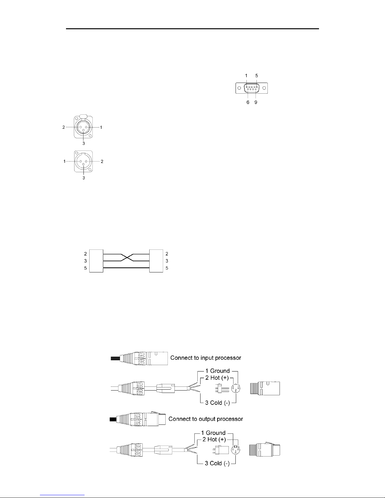
Connectors and connections.
XLR CONNECTORS
9 Contacts Male SUB-D CONNECTOR
INPUTS (Communication PC-User interface)
1.- GROUND
2.- HOT (+) Pin 1 : n.c.
3.- COLD (-) Pin 2 : RxD - Received Data
Pin 3 : TxD – Transmitted Data
Pin 4 : n.c.
OUTPUTS Pin 5 : Ground
1.- GROUND Pin 6 : n.c.
2.- HOT (+) Pin 7 : n.c.
3.- COLD (-) Pin 8 : n.c.
Pin 9 : n.c.
CONEXION CABLE PC – LMS 221 / LMS 266
(Supplied)
9 Contacts Female 9 Contacts Female
Sub-D (PC) Sub-D (RS-232 IN)
AERIAL XLR CONNECTORS
Page 9
RAM Audio LMS 266 / LMS 221 Digital Controller – Hardware Manual
8
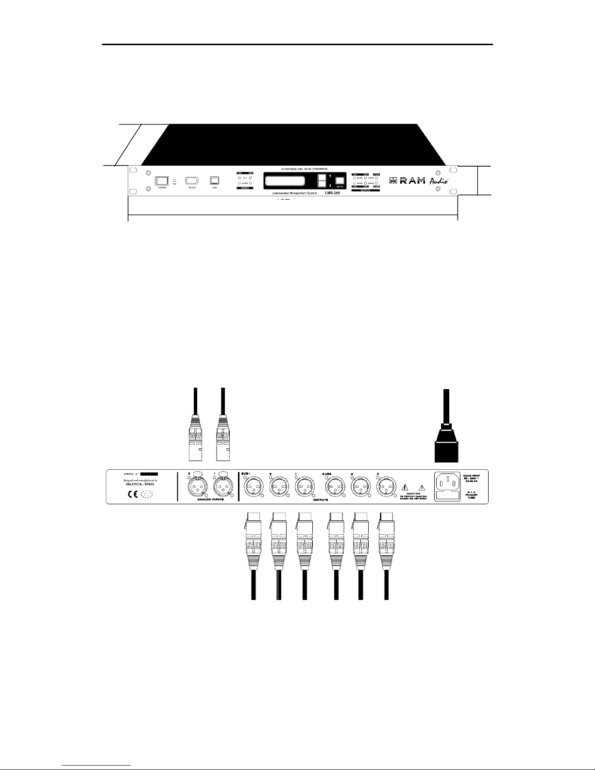
Dimensions LMS 221 / LMS 266 (mm)
45
How to connect LMS 266
INPUTS
2 1 MAINS CABLE
SUB1 2 1 SUB2 4 3
OUTPUTS
45
226
482
Page 10
RAM Audio LMS 266 / LMS 221 Digital Controller – Hardware Manual
9
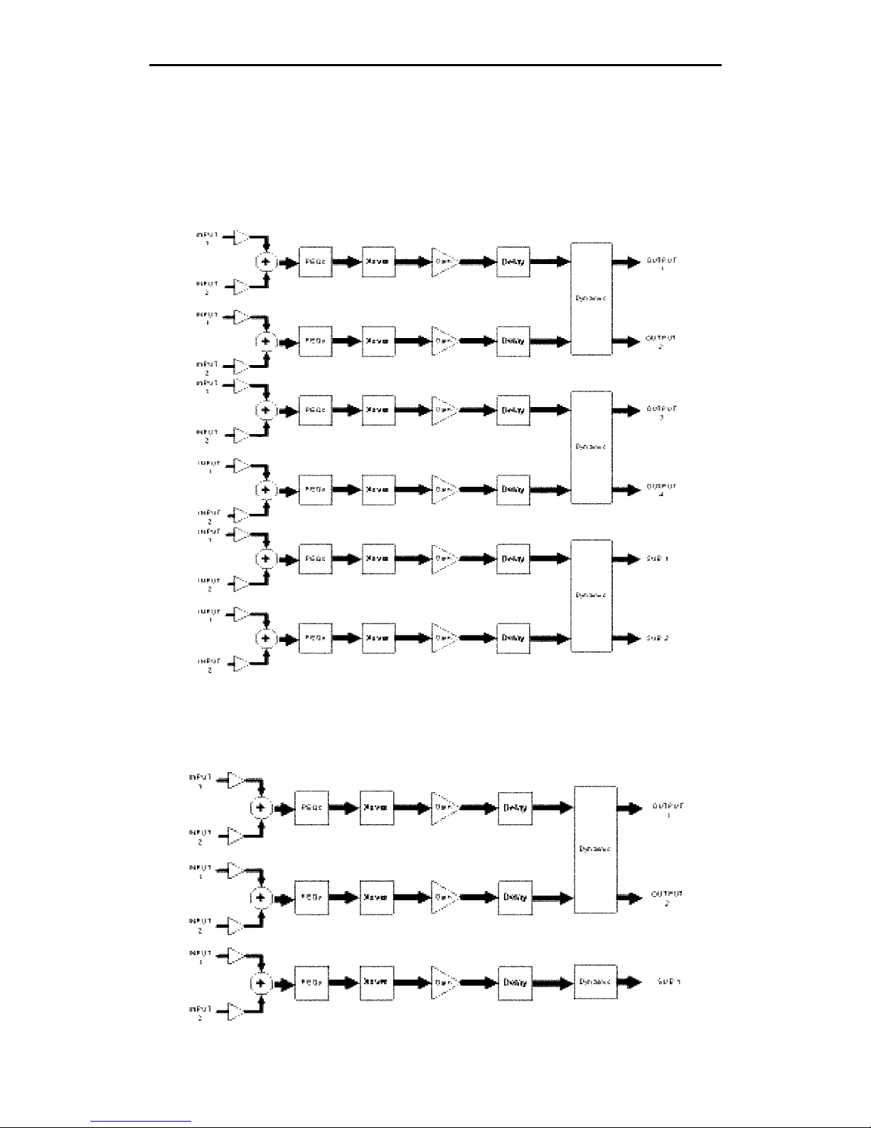
3.- PROCESS DIAGRAM
Once the analogical input signal is converted into a digital input signal, the process inside the
DSPs is the following:
Block diagram LMS 266
Block diagram LMS 221
Page 11
RAM Audio LMS 266 / LMS 221 Digital Controller – Hardware Manual
10
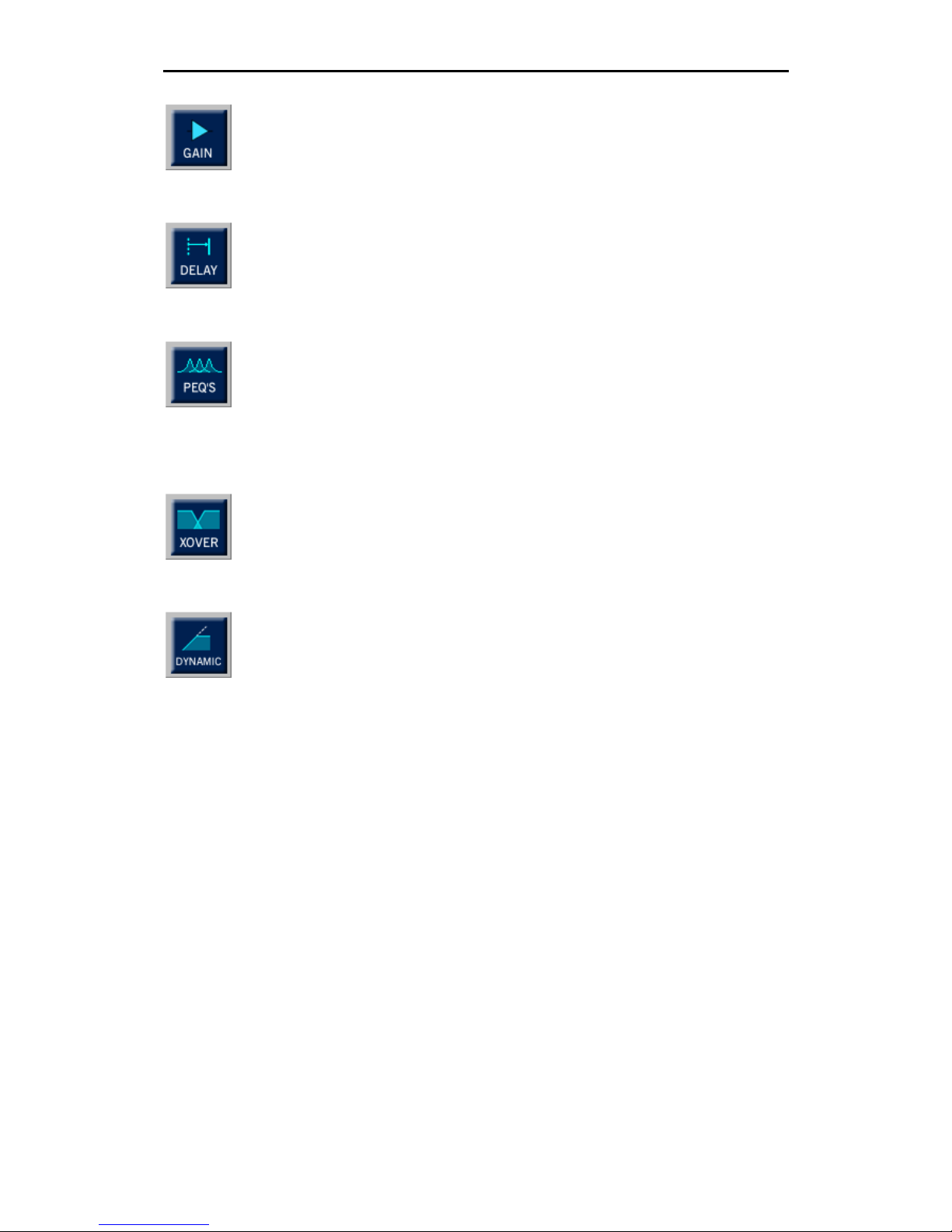
GAIN: Gain control. Adjust every way’s gain to adapt the signal level received
from the mixing desk and adjust the level delivered to each amplifier and level
the sensibility of each way.
DELAY: Configurable delay. In each output we dispose of 4.85mseg. With the
delay it is possible to correct the sound boxes´ positioning in a multi way
system and avoid cancellation problems caused by phase problems.
PEQ: Equalization. There are 7 totally configurable filters per way. These filters
can be Parametric, Shelving of Low and High of 6dB/oct, LowPass, HighPass
(with and without Q), BandPass, StopBand and AllPass of first and second
order. PEQs mission is to correct and optimize each transducer and its
enclosure’s respond, obtaining a flat frequency or other, as required.
CROSSOVER: Bands separating filters. There are Linkwitz-Riley, Butterworth
and Bessel filters up to 24dB/oct. You can also put them into Bypass,
inactivating them, so this way disposing of the corresponding way in full band.
DYNAMICS: Dynamics section. The LMS 221 / LMS 266 has a sophisticated
algorithm of dynamics which uses a RMS detector with attacks and liberation
controllable through the respond speed constants of the dynamics. Includes
dynamic curves C. R. I. (Continuous Ratio Increment). These dynamic curves
work like a compressor-limiter with ratio depending of the signal level,
progressively passing from a relation 1:1 to 1:∞. This way the dynamics control
beginning is gradual and totally transparent and guarantees much more
headroom than a traditional limiter. There is also a noise gate available, which
will respond with the time constants of the general dynamics.
Page 12

RAM Audio LMS 266 / LMS 221 Digital Controller – Hardware Manual
11
4.- OPERATION
Use Procedures
a.- Before switching on
LMS 221/ LMS 266 includes a precise self-regulated switching power supply. This means that it
can adapt to every voltage between 85 and 265 volts and frequencies between 50 and 60Hz.
This way the processor’s perfect working order is guaranteed under any voltage supply, so the
final sound quality does not depend of the mains voltage state or generator used. Nevertheless,
it is always recommendable to check the net voltage first to avoid possible problems as to
connect the controller to 380 volts. LMS 221 / LMS 266 includes a fuse holder with a spare fuse
(1A) in the connector’s input IEC of the mains cable.
Please turn the volume of the amplifier down before you switch the processor on. This way later
we can check that every processor’s output is connected to its corresponding amplifier, avoiding
possible irreparable damages of the loudspeaker (mainly the drivers).
In an installation it is convenient to connect the audio and lighting systems in independent
voltage lines to separately protect two parts and minimize the interferences between the
systems.
b.- After switching on
Turning on the LMS 221 / LMS 266, the audio outputs will remain short-circuited to ground for a
few seconds in order to avoid the dangerous transitories in the switching on, so the processor
waits for a stable voltage and carries out intern verifications (working order of converters, check
the work memory, DSP processors starting and loading of the actual configuration.). Afterwards,
if all is working well, all the outputs commute at the same time introducing the audio in each
output.
To check the correct connection between LMS 221 / LMS 266 and the power amplifier,
introduce audio into the processor (the green front LEDS signal will light) and increase the
volume of the amplifiers channel by channel, checking that every way outputs attacks its
corresponding amplifiers.
Page 13
RAM Audio LMS 266 / LMS 221 Digital Controller – Hardware Manual
12
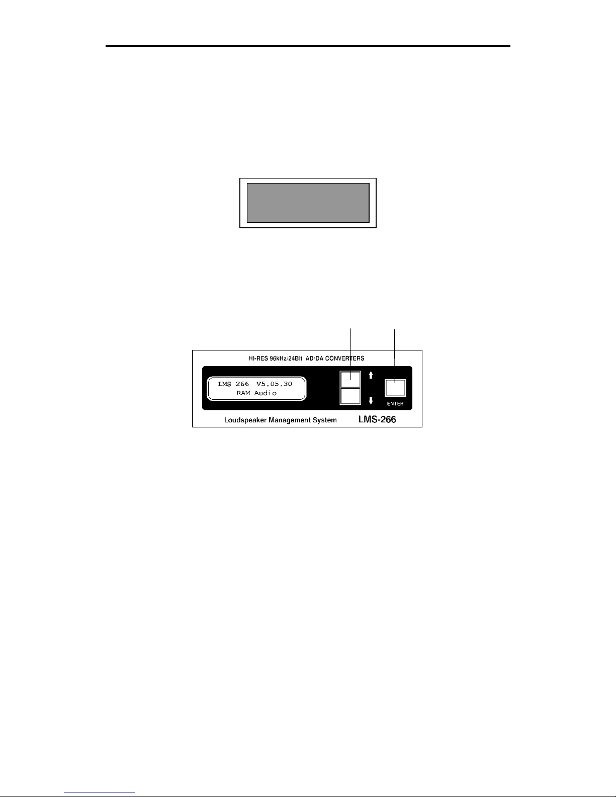
Display and edition elements
For the programming of some of its functions, the processor LMS 221 / LMS 266 has a LCD
screen, two menu keys and an enter key, for the detailed configuration of the actions on the
different menus. For its entire configuration, the software LMS 221 / LMS 266 Control is
necessary.
On the display you will find the specific information on the actions to which you can gain access
to the configuration menus.
DESCRIPTION OF THE ELEMENTS FOR THE EDITION
The elements for the edition permit the modification of the options inside the menus, as well as
the navigation through the menus and submenus.
MENU KEYS ENTER
MENU KEYS: allows us to move up and down in the menu, as well as to increase and decrease
the edited parameters´ value.
Pushing the upper key we move upward in the menus or increase the parameters´ value.
Pushing the lower key we move downward in the menus until the main menu or decrease the
parameters´ value.
ENTER: Key to confirm the actions in the menus.
Allows the access to the menus and submenus.
LMS 266 V5.05.30
RAM AUDIO
Page 14
RAM Audio LMS 266 / LMS 221 Digital Controller – Hardware Manual
13
Program menu
The processor LMS 221 / LMS 266 has a LCD screen on which you can find configuration
menus which allow you to store and modify the working order options of the processor, as well
as to protect and have access to your stored data.
These menus are:
- 1.- CONFIGURATION
- 2.- INFORMATION
- 3.- COMMUNICATION
In each of them exist different submenus, which allow a total and easy configuration of the
processors working order parameters.
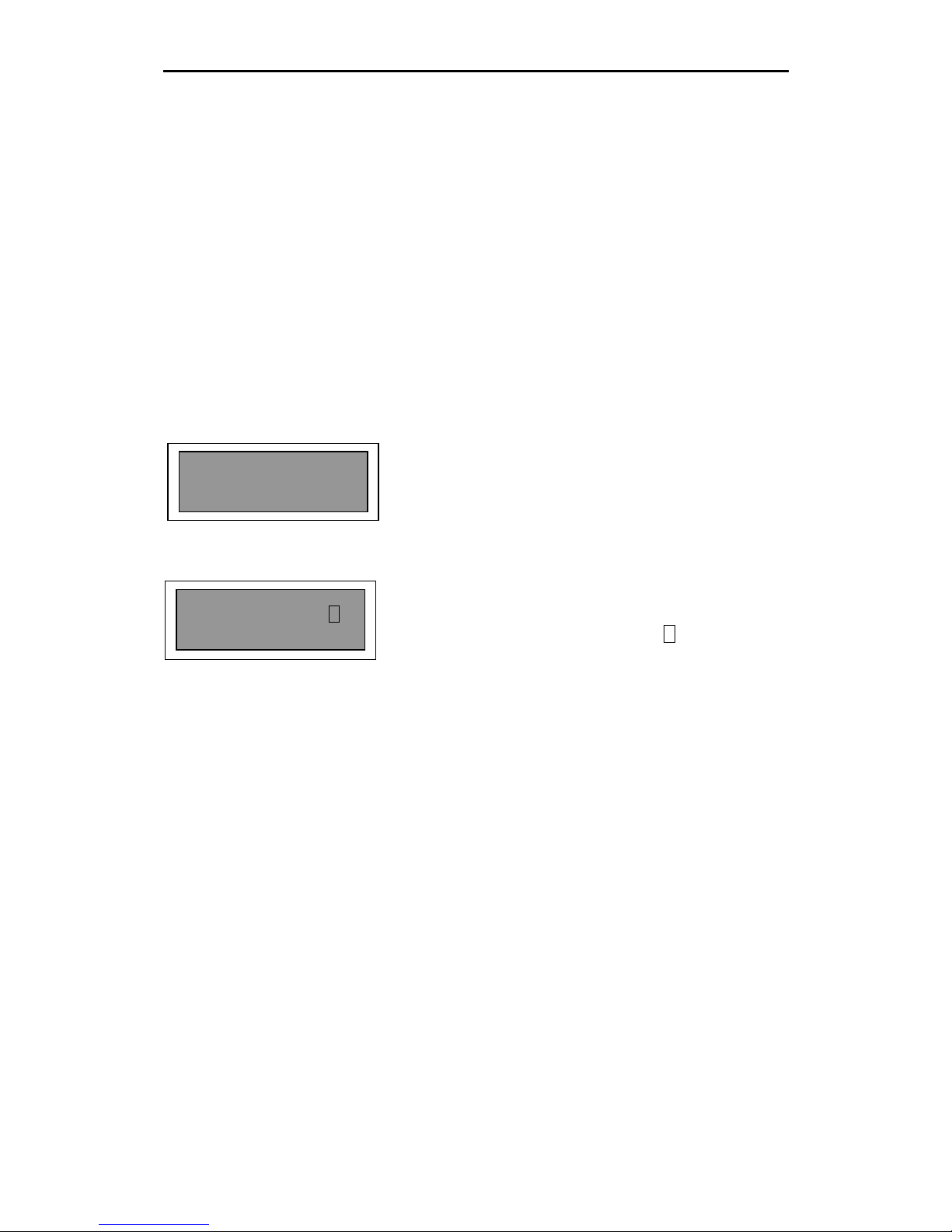
When you switch on the processor, the following session start menu appears:
Welcome menu. It shows the version of the
microcontroller software in the first line.
Program access menu. The name of the actual
program appears in the first line. Pressing the Enter
key allows you to enter in the detailed configuration of
the processor’s functions. The letter A indicates that
the access is analogical.
The menu keys allows to directly select another
program. Once you have chosen a new configuration,
press Enter. This way you can avoid accidental
program changes.
LMS 266 V5.05.30
RAM AUDIO
1. Program Name A
Push for menu
Page 15
RAM Audio LMS 266 / LMS 221 Digital Controller – Hardware Manual
14
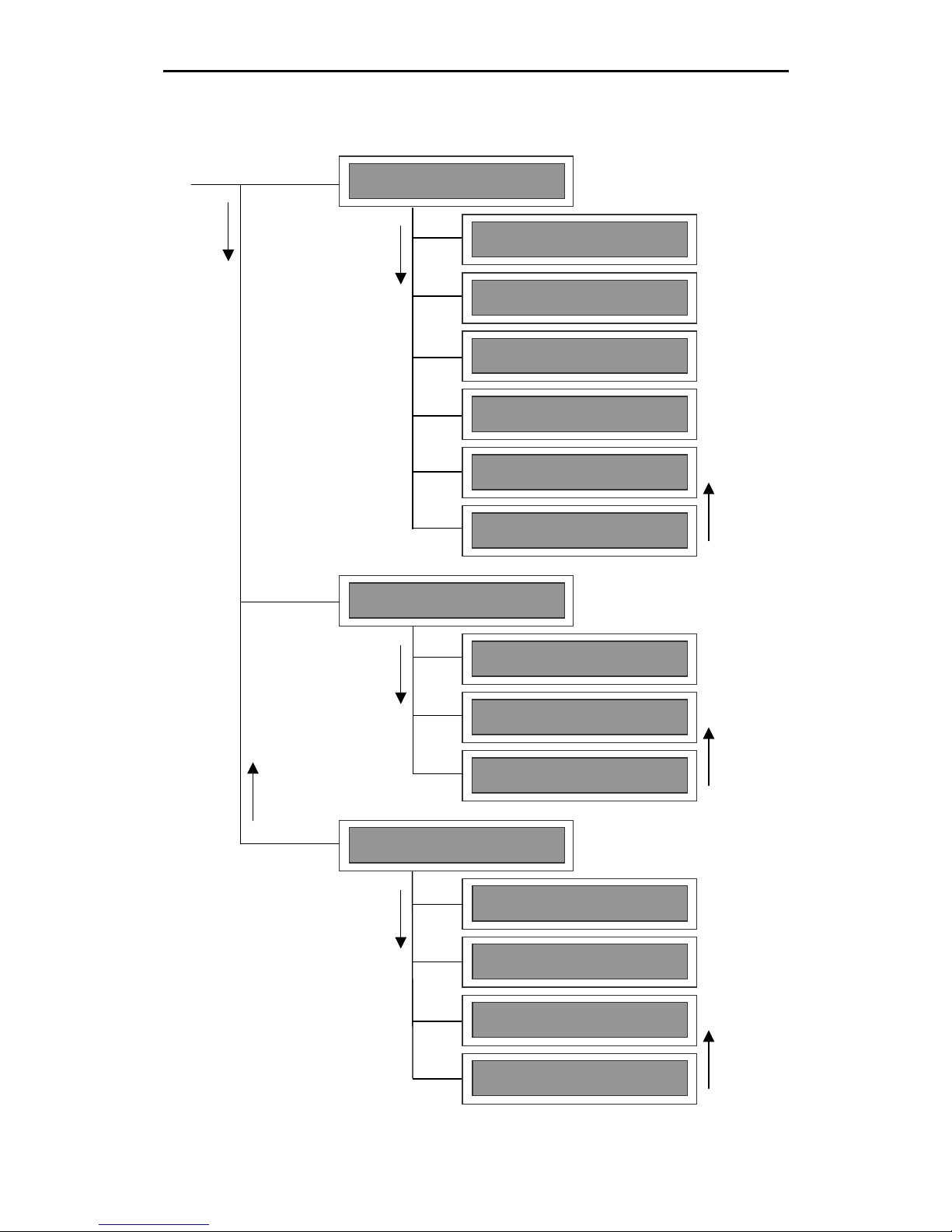
Menu hierarchy
2. Information
2.1 Prot. Mem
2.2 Test LCD
2.3 Version
3. Comunication
3.1 Prepare Clon
3.2 Clone
3.3 Send Memory
3.4 Receive Memo
1. Configuration
1.1 Out Delay
1.2 Gain
1.3 Output POL
1.4 Temperature
1.5 Password
1.6 Protect
Page 16
RAM Audio LMS 266 / LMS 221 Digital Controller – Hardware Manual
15
1.- CONFIGURATION
When pressing the Enter key after the welcome menu, the configuration menu is the first menu
you find. It allows the access to diverse configuration submenus. LMS 221 / LMS 266 disposes
of 60 memories in which you can store your configurations. The user can dispose of all
configurations stored on his hard disk’s PC, introducing the 60 necessary into the processor.
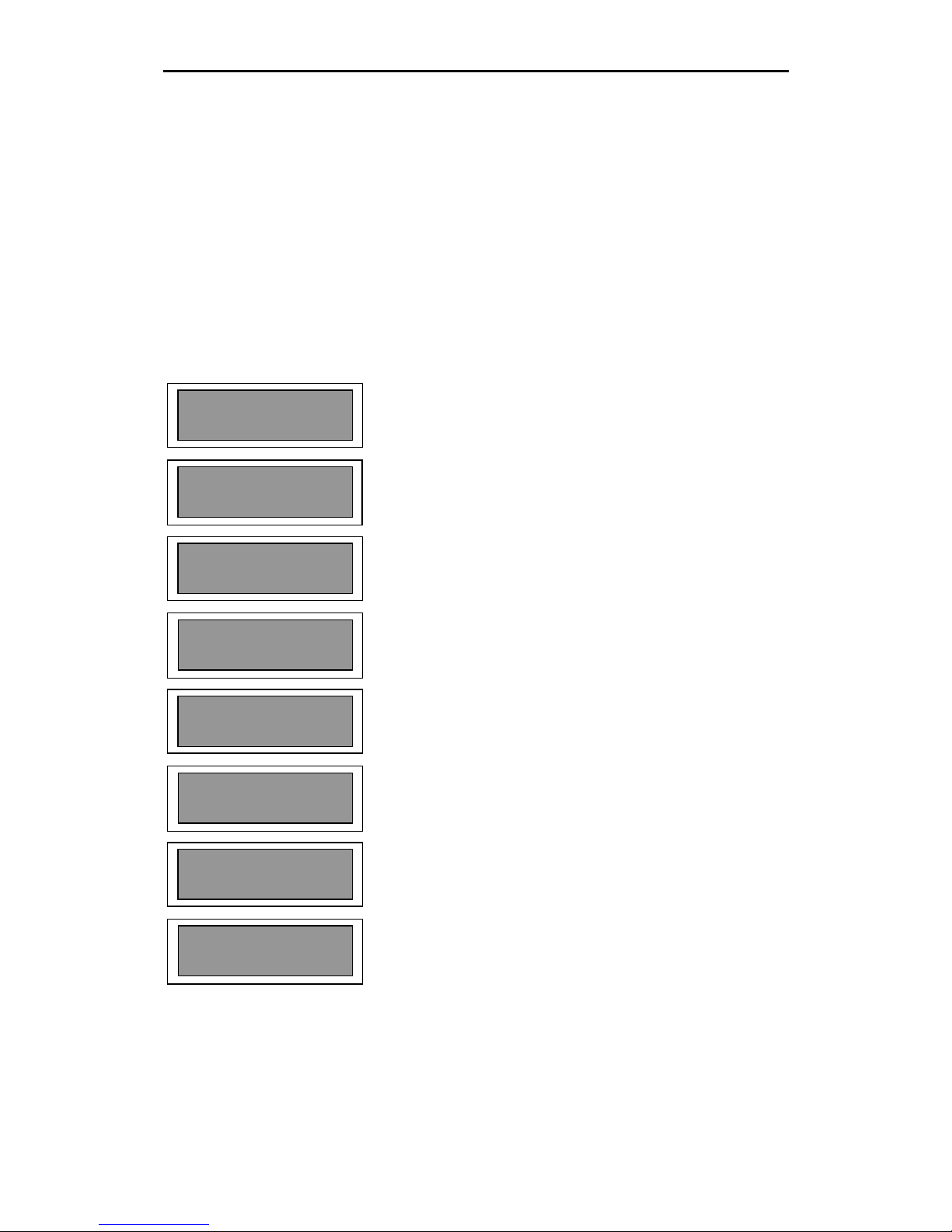
Submenu 1.1. Out Delay.-
Pressing the Enter key from the Configuration menu we pass to the OUT DELAY submenu,
where we can select the output Delay of each way we have.
Pressing the Enter key, from the main menu, we have
access to the submenu in which we will introduce the
Delay value in milliseconds or centimetres for the
output 1.
If we press the Enter key again, we reach the output 2,
in which we repeat the process. Like this we continue
introducing all of the outputs delay
By pressing the Enter key a last time we return to the
Out Delay menu.
The Delay values for the outputs can vary between 0
and 4.84ms (milliseconds), in steps of 0.02ms or
between 0 and 168cm (centimetres).
The processor will indicate for each output, the name
defined by the user through the LMS 221 / LMS 266
Control Software.
Delay SUB 2
0 ms | 0 cm
1.1. Out Delay
Delay Out 3
0 ms | 0 cm
Delay Out 4
0 ms | 0 cm
Delay Out 2
0 ms | 0 cm
Delay SUB 1
0 ms | 0 cm
1.1. Out Delay
Delay Out 1
0 ms | 0 cm
Page 17
RAM Audio LMS 266 / LMS 221 Digital Controller – Hardware Manual
16
Submenu 1.2. Gain
Once we have finished with the Out Delay submenu, if we press the upper key, we will find the
submenu GAIN. It allows to individually defining the input gain for each of the processor’s ways.
To be able to move among the submenus, push the Enter key, inserting the gain values for
each way in the following manner:
From the main menu push the Enter key, which will
allow us to enter into the submenu where we introduce
the gain in dB for Out 1.
If we push the Enter key again, we will enter into the
Out 2 submenu where we will repeat the process,
continuing this way until all gains are defined.
Once all values have been inserted, we will push the
Enter key again to return to the Gain menu.
The gain values can vary from Mute, 30.0dB to +6db,
in steps of 0.1db.
The processor will indicate for each output, the name
defined by the user with the LMS 221 / LMS 266
Control Software.
1.2. Gain
SUB 2 : 00.0 dB
1.2. Gain
1.2. Gain
Out 3 : 00.0 dB
1.2. Gain
Out 4 : 00.0 dB
1.2. Gain
SUB 1 : 00.0 dB
1.2. Gain
SUB 1 : 00.0 dB
1.2. Gain
1.2. Gain
Out 2 : 00.0 dB
Page 18
RAM Audio LMS 266 / LMS 221 Digital Controller – Hardware Manual
17
Submenu 1.3. Output POL
Using the upper menu key in the submenu Gain we will go to the next level above, we will reach
the OUTPUT POL, where we will be able to choose the output’s polarity [+] or [-] of each of the
ways.
In the main menu we press the Enter key and we will
have access to the submenu in which we will insert the
polarity chosen for the output 1.
With the upper and lower menu keys we will change
the polarity. Push the Enter key to insert the actual
polarity and pass on to the next way.
Repeat this process with the rest of the outputs.
The processor will indicate for each output, the name
defined by the user with the LMS 221 / LMS 266
Control Software.
1.3. Output POL
SUB 2 : [+]
1.3. Output POL
1.3. Output POL
Out 3 : [+]
1.3. Output POL
Out 4 : [+]
1.3. Output POL
Out 2 : [+]
1.3. Output POL
SUB 1 : [+]
1.3. Output POL
1.3. Output POL
Out 1 : [+]
Page 19
RAM Audio LMS 266 / LMS 221 Digital Controller – Hardware Manual
18
Submenu 1.4. Temperature
If we press the upper menu key in the OUTPUT POL submenu we will go to the next level
above, Temperature. Here we can choose the temperature for the work environment, which will
be used in the calculation of the delay distances.
Pressing the Enter key, we will enter into the value’s
edition.
To change the value we will press the upper or lower
menu keys. Pressing Enter we validate the value.
1.4. Temperature
1.4. Temperature
1.4. Temperature
Temp: 25 ºC
Page 20
RAM Audio LMS 266 / LMS 221 Digital Controller – Hardware Manual
19
Old Password
AAAAAA
1.5. Password OFF
New Password
ABCDEF
1.5. Password ON
1.5. Password OFF
Submenu 1.5. Password
Going to the next upper level from the submenu Temperature, we will reach the submenu
PASSWORD OFF (ON), in which we can include an access password to protect the setting
data loaded in the processor.
In the main menu we press the Enter key and will have
access to the submenu where we will be asked for the
current password. We will dispose of 6 alphanumeric
characters.
If we do not know it or if we enter a wrong access
password, the message Password ERROR will appear
on the screen and will return to the main submenu
screen.
If we enter the correct access password we can
change and activate it or not.
If you press the Enter key after activating it, it will be
deactivated again.
NOTE: If you cannot change the password because you do not know it, you have to connect the
processor to a PC and with the help of the software LMS 221 / LMS 266 Control System,
program a new password.
Page 21
RAM Audio LMS 266 / LMS 221 Digital Controller – Hardware Manual
20
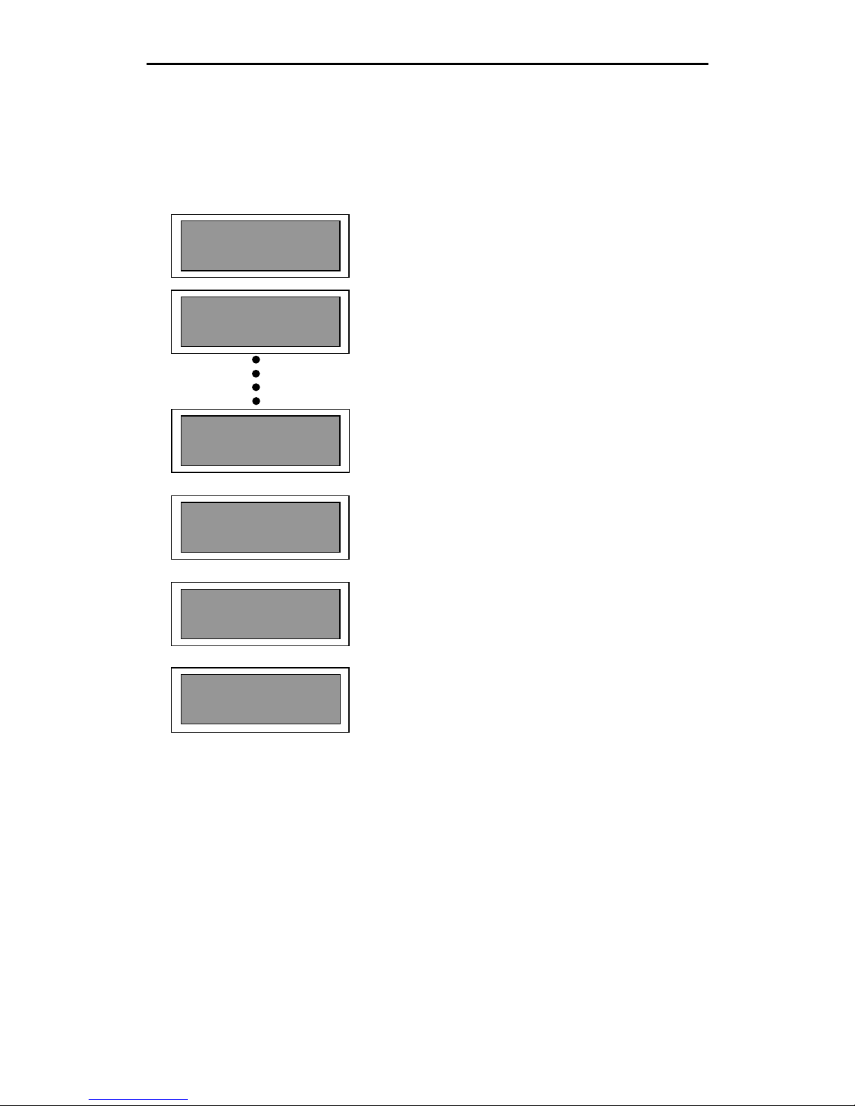
Submenu 1.6. Protect
Going up from the submenu PASSWORD with the upper menu key, we reach the submenu
PROTECT where we can activate and deactivate the protection of each of the 60 memories that
we have.
In the main menu we press the Enter key and enter
into the submenu in which we activate the protection of
the memory 1. Activating this option, on the left side of
the memory number, there will appear the mark (√ )
indicating that it is now protected.
With the menu key we navigate through the different
memories, activating and deactivating the protection for
each of them.
If we press the Enter key, in any window of the
program’s submenu, we will reach a window of
confirmation of our action (activation or deactivation of
the protection). Once finished all the actions in the
memories, we will press the lower menu key until we
reach the main screen of the submenu PROTECT.
1.6. Protect
60.Program Name
Are you sure?[E]
√ 1.Program
1.6. Protect
Are you sure?[E]
1.Program Name
1.6. Protect
1.6. Protect
1.Program Name
Page 22
RAM Audio LMS 266 / LMS 221 Digital Controller – Hardware Manual
21
2. Information
2.1. Prot. Mem
10 Protected
2.- INFORMATION
In this menu and the associated submenus, the user is informed of a series of parameters
contained in the processor. Some of them are part of the software and others part of the
personalized configuration, like free and protected memories.
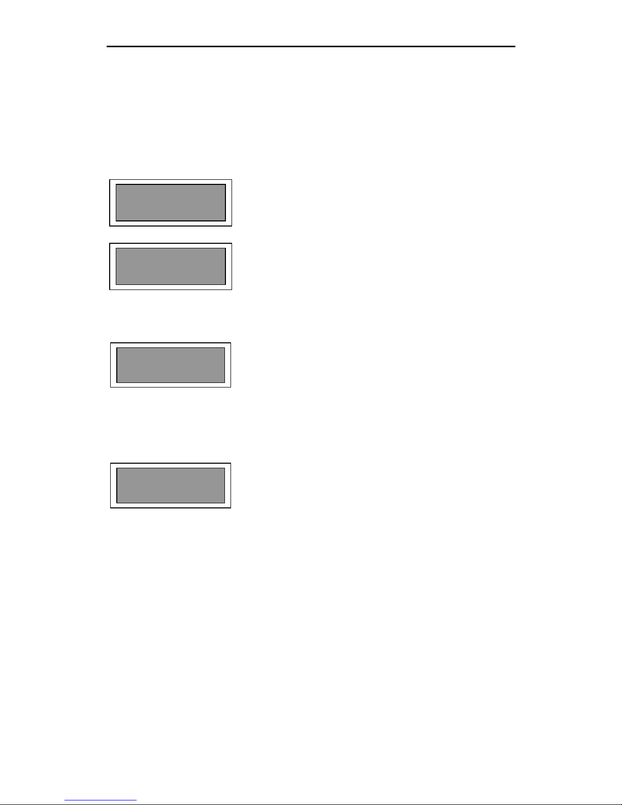
Submenu 2.1. Protect Memory
When we press the Enter key on the Information
screen, the submenu Prot. Mem is the first we reach.
Pressing the Enter key, here we will be given
INFORMATION on how many program memories are
protected.
In this case there are 10 memories protected.
Submenu 2.2. Test LCD
If we go up with the upper menu key we reach the
submenu Test LCD. From this screen we can carry out
a LCD check and see if all the pixels are correct.
Submenu 2.3. Version
If we continue going up, we reach the submenu
version. On this screen we receive information on the
microcontroller software Version installed in our
processor.
2.2. Test
LCD
2.3. Version
5.05.30
Page 23
RAM Audio LMS 266 / LMS 221 Digital Controller – Hardware Manual
22
3.1. Prepare Clon
3. Comunication
Prepare to CLON
Waiting for data
Program Name
Push for Menu
Receiving Data 25%
3.- COMMUNICATION
If we go one level up from the Information menu, the Communication menu appears.
This menu is the one which allows the communication between two processors by cloning,
creating an exact copy of the information of the first processor (the loaded configurations as well
as the operative system of the processor). In our case the processor receives the information of
another processor, working as a master.
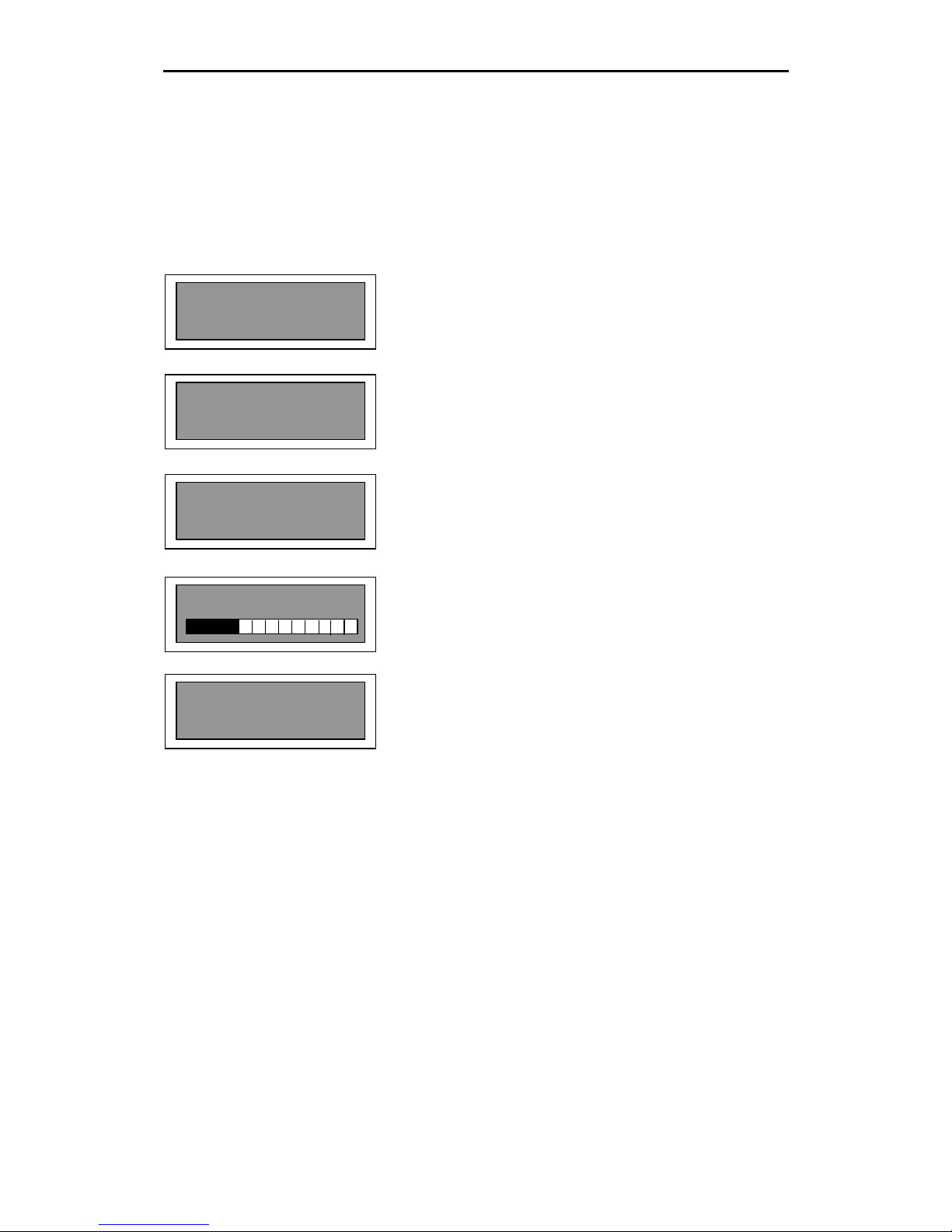
Submenu 3.1. Prepare Clon.-
If we press the Enter key in the main menu, the
submenu 3.1, PREPARE CLON, appears.
This screen advises us to keep the processor ready to
be cloned.
A second screen informs us that the processor is
prepared to receive information from the master
processor (the one which sends the information).
A next screen informs us of the process of cloning,
showing the percentage of information receiving.
When the process has terminated a window with the
program’s name appears.
Page 24
RAM Audio LMS 266 / LMS 221 Digital Controller – Hardware Manual
23
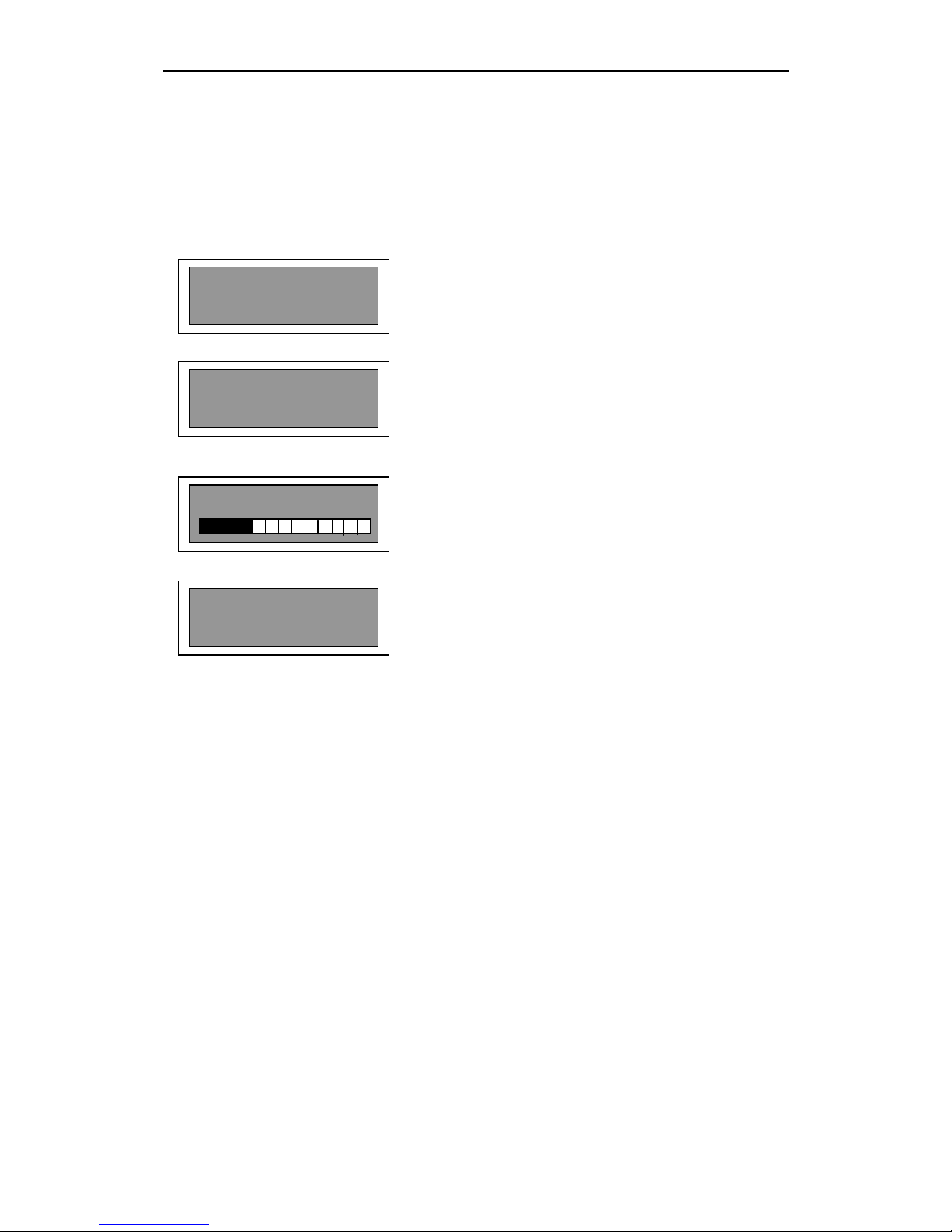
Submenu 3.2. Clone
Going up from the submenu Prepare Clon, the submenu CLONE appears. This menu allows
the cloning (make an exact copy) using our processor as the master, meaning that this
processor is going to send the information to the other processor.
If we press the Enter key on the menu’s main screen,
the submenu 3.2. Clone appears.
Here we receive the advice to prepare the processor to
be cloned and to press the Enter key to start the
process.
A next screen informs us of the cloning process,
showing the percentage of information, which is being
sent.
When the process has terminated a window with the
program’s name appears.
NOTE: In the case of data transmission’s problems or when the processors are not correctly
connected, a screen with the words: Communic. Error will appear.
3.2. Clone
Prepare to CLON
Push to start
Program Name
Push for Menu
Sending Data 25%
Page 25
RAM Audio LMS 266 / LMS 221 Digital Controller – Hardware Manual
24
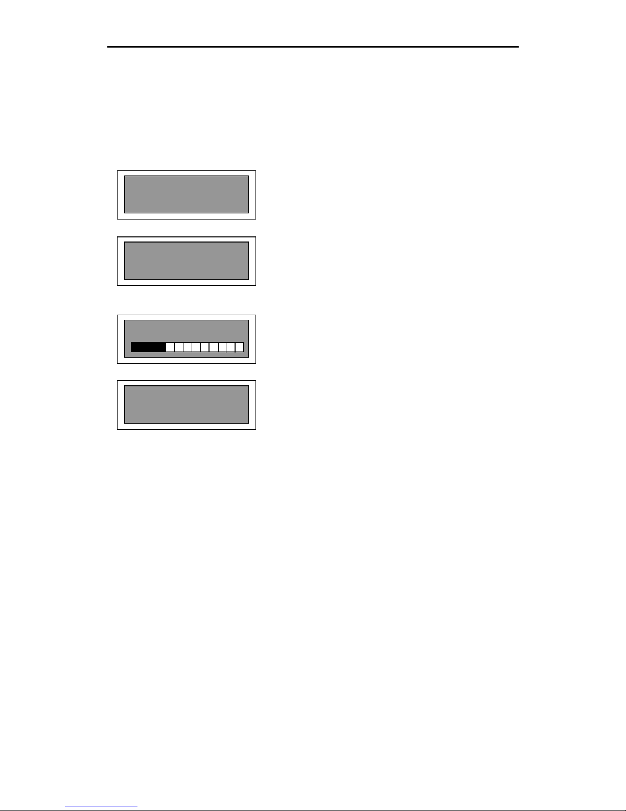
Submenu 3.3 Send Memory
Going up from the submenu Clone the submenu SEND MEMORY appears. This menu allows
to copy a particular memory from a unit of LMS 221 / LMS 266 to another, using our processor
as a master meaning that it is going to send the information to the other processor.
Pushing the Enter key, allows choosing the memory
which is going to be sent to another processor.
Here we receive the order to prepare the processor
which is going to receive the information, pressing the
Enter key the process will start. For this, first the LMS
221 / LMS 266 which is going to receive the memory
needs to be waiting in the submenu 3.4 Receive
Memory.
A next screen informs us of the process of cloning,
showing the percentage of information which is being
sent.
When the process has terminated a window with the
program’s name appears.
NOTE: In the case of data transmission’s problems or when the processors are not correctly
connected a screen with the words: Communic. Error will appear.
3.3. Send Memory
Prepare to SEND
Push to start
Program Name
Push for Menu
Sending Data 25%
Page 26
RAM Audio LMS 266 / LMS 221 Digital Controller – Hardware Manual
25
Submenu 3.4. Receive Memo
Going up from the submenu Send Memory, the submenu RECEIVE MEMO appears, which
allows to receive a particular memory from a unit of LMS 221 / LMS 266, using our processor as
a slave, meaning that it will receive the information from the other processor.
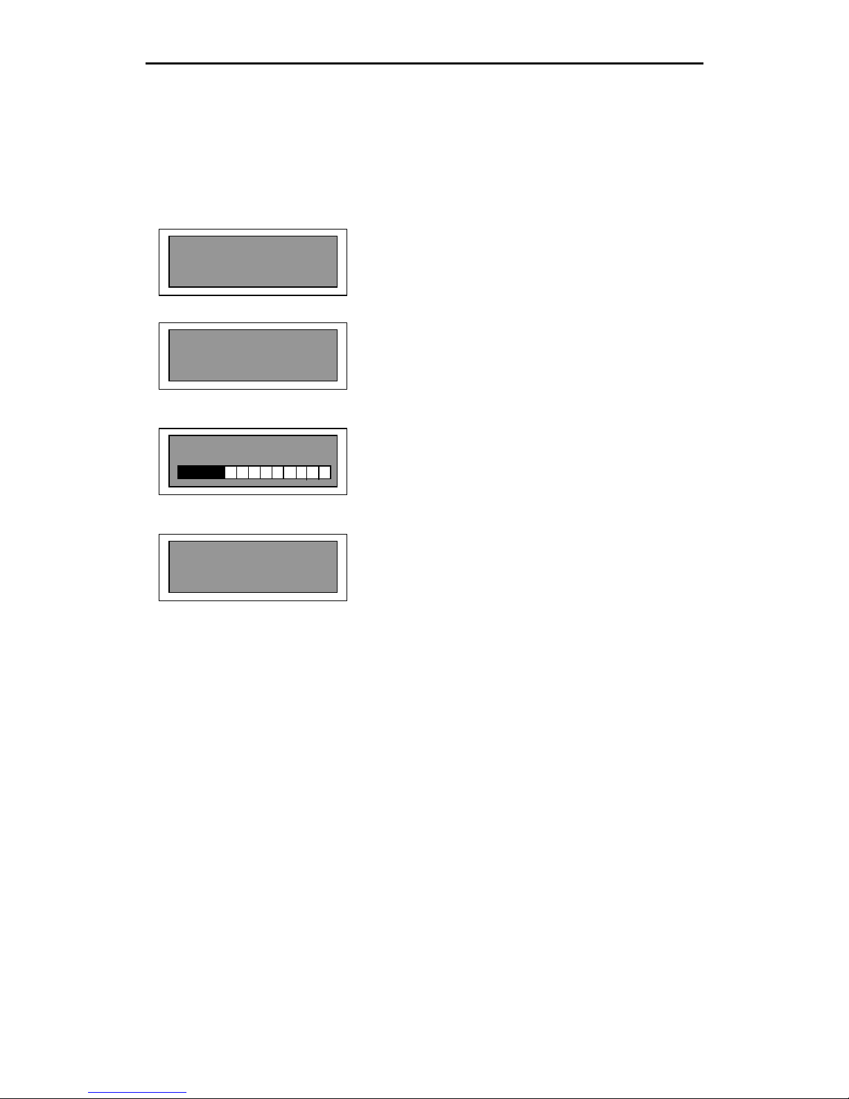
With the menu keys we select the memory in which the
received information will be saved. Pressing the Enter
key we move to the next screen.
Here we are informed that the processor is waiting to
receive the data from the other unit of LMS 221 / LMS
266. Pressing any key you exit from this option,
returning to the main screen.
As soon as the process begins, the following screen
informs us of the cloning process, showing the
percentage of information which is being received.
When the process has terminated a window with the
program’s name appears.
3.4. Receive Memo
Memory: 1
Prepare to CLON
Waiting for data
Program Name
Push for Menu
Sending Data 25%
Page 27

RAM Audio LMS 266 / LMS 221 Digital Controller – Hardware Manual
26
5.- TECHNICAL SPECIFICATIONS
Analogical input Input impedance: 32 KOHM, BALANCED
Connector: Balanced XLR (pin 2+), Balanced
Converter AD: 24 bit-96 KHz, 256x Oversampling
Dynamic Range: 105 db
Max. Input level: +15dBu, Balanced
RF (radiofrequency) filter to avoid interferences
Output Output impedance: 50 OHM
Connector: XLR Balanced (pin 2+)
Converter DA: 24 bit-48 KHz, 256x Oversampling
Dynamic Range: 112 db
Max. Output Level: +18dBu, Balanced
RF (radiofrequency) filter to avoid interferences
THD(%) <0.002%
Frequency Response 10Hz - 24000Hz
Processing 2 Floating Point DSP (1 DSP for LMS 221)
Internal resolution of 48 bits with double precision
Data memory Flash type memory to store 60 Presets.
Total Memory: 128 Kbytes
Power Supply Self regulated Switching Power Supply Universal 85V – 265V, 50Hz -
60-Hz. Fuse holder included in the mains IEC connector with spare
fuse (1A)
Consumption 12W
Communication USB and RS-232C
Interface
Finish Chassis: black iron panel, 1.5mm thick
Front Panel: anodized aluminium, 4mm thick
Environment Work temperature: 0º to 50ºC (32º to 122ºF)
Storage temperature: -30º to 70ºC (-22º to 167ºF)
Maximum humidity: 90%
Dimensions 482 x 226 x 45 mm
(WxDxH)
Weight 3Kg
Guaranty 1 year
Page 28

RAM Audio LMS 266 / LMS 221 Digital Controller – Hardware Manual
27
6.- PROBLEMS SOLUTION
This section is dedicated to give possible solutions for problems in the working order, which are
easy to solve.
1 – The LMS 221 / LMS 266 is not active.
Check the main cable. If it is correctly connected and the blue power LED does not light, check
the fuse located in the mains input.
2 – The LMS 221 / LMS 266 turns on but there is no sound.
Check that the signal is being send to the processor correct input, 1 or 2. If there is sufficient
signal, the green signal LED will be lighting; if not, check the cabling from the mixing desk to the
processor.
3 – The obtained sound is strange.
Check the correct connection between the outputs and their corresponding power amplifiers.
Some ways could be changed. Always increase the amplifiers’ volume bit by bit and way by way
to ensure a correct wiring and avoid that the transducers is being damaged.
4 – One power amplifier (with the same signal as the rest) sounds less.
Check if the cable, which connects the processor and the amplifier, is balanced. If not, the
output signal will decrease 6dB.
5 – The audio sounds distorted and not good.
Check that the input is not saturated (exceeding 15 dbu or 4.4 volts of input) In this case the red
clip LEDs will be lighting. You will only have to reduce the signal to processor’s input until the
clip LEDs turn off. If the problem cannot be solved this way, check that the signal does not
come out distorted from the previous appliance, for example the mixer, which could have a high
gain in this way and saturate the sound mixer’s input.
Page 29

RAM Audio LMS 266 / LMS 221 Digital Controller – Hardware Manual
28
7.- GUARANTEE
The RAM Audio products are guaranteed against any kind of manufacture defect for the period
of one year beginning from the day of purchase.
During this period, RAM Audio guarantees the repair and the supply of the necessary spare
parts free of charge. If the product cannot be returned to the factory for inspection and repair,
RAM Audio will supply all necessary spare parts.
During the guarantee’s validity, RAM Audio does not assume the responsibility for any damages
or defects caused by transportation, bad use or inappropriate manipulation of persons who do
not belong to RAM Audio staff or to its authorized services.
RAM Audio appreciates your trust in this product and hopes it will meet your expectations.
Page 30

RAM Audio LMS 266 / LMS 221 Digital Controller – Hardware Manual
29
All rights reserved. The reproduction of the products or part of the products in any way, without
the written authorization of RAM Audio is strictly forbidden.
RAM Audio cannot be hold responsible by the purchaser of this product nor by third parties for
damages, losses, costs or expenses by the purchaser as a result of an accident, bad use or
abuse of this product or modifications, repairs or changes of the product or in the case of not
strictly following the instructions of working order and maintenance of RAM Audio.
LMS 221 / LMS 266 are commercial marks of RAM Audio.
Microsoft & Windows are registered brand marks of Microsoft Corporation.
Other product names used in this document are only used for identification and are only
commercial marks of their respective owners.
Page 31

RAM Audio LMS 266 / LMS 221 Digital Controller – Hardware Manual
30
RAM Audio continually investigates to improve the quality of its products. The specifications
explained in this manual can vary without previous notice. In any case, a new RAM Audio
product will have the same or considerably better specifications.
Manufactured by C.E. Studio-2 s.l.
Pol. Ind. La Lloma, C/ Sierra Parenxisa, nº 28
46960 Aldaya, Valencia – SPAIN
www.ramaudio.com
 Loading...