

Page 1
MODEL GDF28
Fry Dispenser
EQUIPMENT MANUAL
English (Rev. F)
P/N 291635
Manufactured by
AFD-280E
Automated Equipment, LLC
5140 Moundview Drive
Red Wing, MN 55066 U.S.A.
PHONE: 1 (651) 385-2273
FAX: 1 (651) 385-2166
SERVICE FAX: 1 (651) 385-2172
FOR SERVICE in the U.S.A./CANADA, CALL:
1 (800) 248-2724
http:// www.autoequipllc.com
Business Hours: 8:00 AM – 5:00 PM CST
After hours, your call will be handled by a pager service;
a Technical Support Representative will return your call.
INTRODUCTION _____________________________________________________________________ 3
SPECIFICATIONS____________________________________________________________________ 3
FCC STATEMENT____________________________________________________________________ 3
WARRANTY ________________________________________________________________________ 4
REQUESTING SERVICE, ASSISTANCE, OR PARTS________________________________________ 5
SAFETY____________________________________________________________________________ 6
ASSEMBLING THE DISPENSER ________________________________________________________ 7
DAILY SET-UP ______________________________________________________________________ 8
DAILY CLOSING_____________________________________________________________________ 8
OPERATOR CONTROLS ______________________________________________________________ 9
SEQUENCE OF OPERATION __________________________________________________________ 11
CONTROLLER FUNCTIONS ___________________________________________________________ 13
ERROR CODES _____________________________________________________________________ 16
TROUBLESHOOTING ________________________________________________________________ 25
ADJUSTMENTS AND DIAGNOSTICS ____________________________________________________ 27
CONTROLLER BOARD LAYOUT _______________________________________________________ 29
GDF28 SCHEMATIC __________________________________________________________________ 31
PART IDENTIFICATION _______________________________________________________________ 33
BASKET LIFT ASSEMBLY_____________________________________________________________ 36
NEW BASKET LIFT ASSEMBLY ________________________________________________________ 37
STOPGATE DRIVE ASSEMBLY ________________________________________________________ 38
ACCUMULATOR ASSEMBLY __________________________________________________________ 39
DRUM MOTOR ASSEMBLY____________________________________________________________ 41
LIFT SADDLE ASSEMBLY_____________________________________________________________ 41
NON-CONTACT WEIGHING SYSTEM ASSEMBLY (NCWS) __________________________________ 42
TABLE OF CONTENTS
Copyright © 2005 Automated Equipment LLC. All Rights Reserved
Page 2

GDF28 Dispenser
The information in this manual is subject to change without notice.
IN NO EVENT WILL AUTOMATED EQUIPMENT LLC BE LIABLE FOR TECHNICAL OR
EDITORIAL OMISSIONS MADE HEREIN; NOR FOR DIRECT, SPECIAL, INCIDENTAL, OR
CONSEQUENTIAL DAMAGES RESULTING FROM THE FURNISHING, PERFORMANCE, OR
USE OF THIS MATERIAL.
This manual is copyrighted with all rights reserved. Under the copyright laws, this manual may
not be copied, in whole or part, without the written consent of Automated Equipment LLC
Product names mentioned herein are for identification purposes only, and may be
trademarks and/or registered trademarks of their respective companies.
Copyright © 2005 Automated Equipment LLC. All Rights Reserved
2
Page 3

GDF28 Dispenser
INTRODUCTION
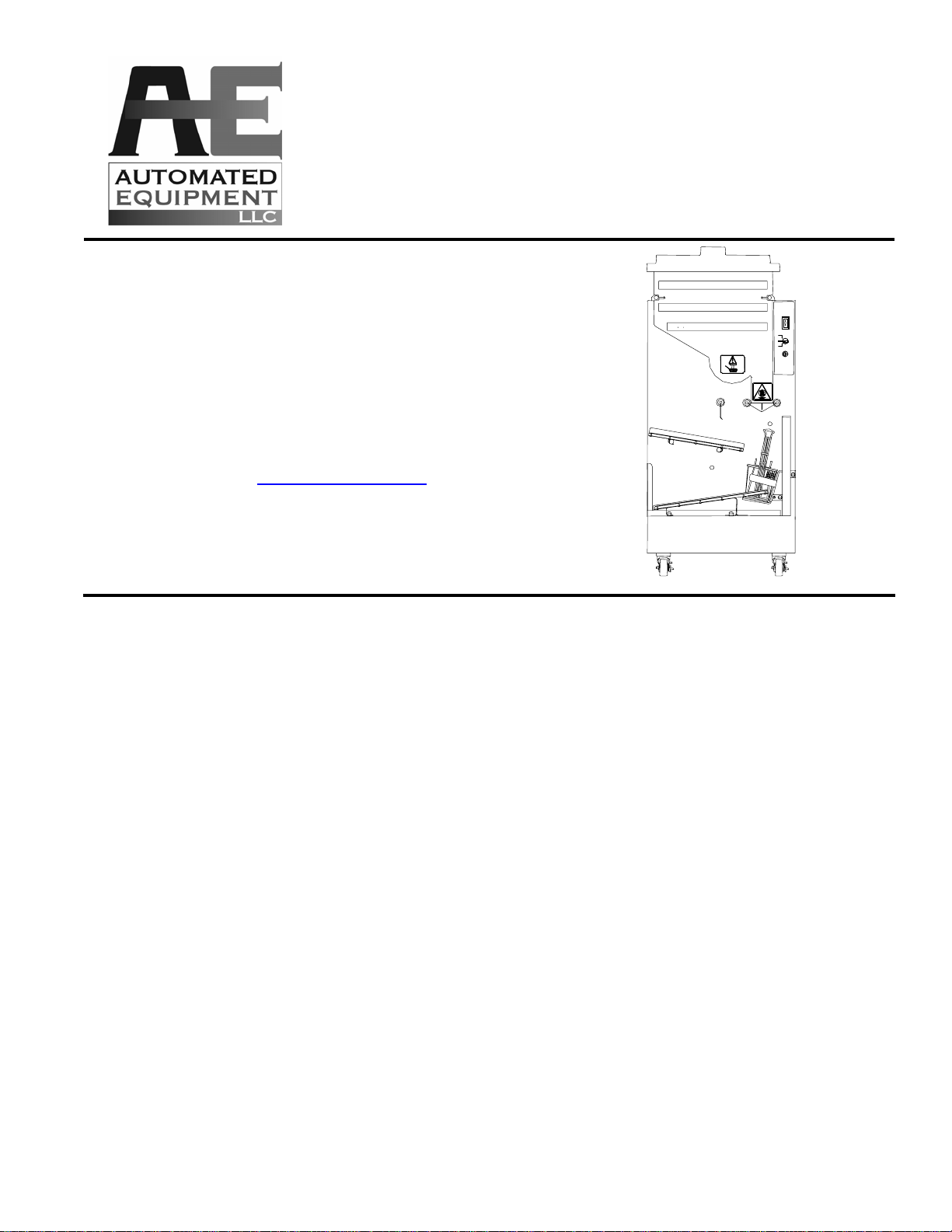
The Dispenser is a compact automated system
that replaces manual basketing of frozen french
fries. The Dispenser automatically weighs 12
ounce (350 gm), 16 ounce (450 gm) or 24 ounce
(700 gm) loads of frozen fries and dispenses them
into custom fry baskets.
The Dispenser's Hopper holds 42 lbs. (19 kg) of
frozen french fries prior to basket loading. A
rotating Dispenser Drum inside the Hopper
transfers the frozen fries onto the Accumulator
Doors where a weight sensor accurately weighs
the fries.
Empty baskets are manually placed on the Upper
Guide. The baskets slide under the Accumulator
Doors where fries are dispensed into them. The
Basket Lift then lowers the filled baskets onto the
Lower Guide where the baskets wait to be picked
up by a crew person.
INTENDED USE
The GDF28 Dispenser is intended to dispense
only frozen french fries. All food should be stored
and handled according to industry
recommendations. The GDF28 Dispenser is not
intended to be used for storage of food and
should be cleaned regularly as described in the
manual in order to avoid spoilage and
contamination.
HAZARD COMMUNICATION STANDARD (HCS)
The procedures in this manual may include
the use of chemical products. These chemical
products will be highlighted with boldface
letters followed by the abbreviation (HCS) in
the text portion of the procedure. See the HCS
Manual for the appropriate Material Safety
Data Sheets (MSDS).
NOTE: This equipment is manufactured in the
U.S., therefore all hardware measurements are in
English, and the metric conversions stated are
approximate.
ADAPTIVE WEIGHT TECHNOLOGY
This Dispenser utilizes adaptive weight
technology. This allows the optimal parameters
used in weighing to be learned for the product
being dispensed. It varies the Drum rotation
speed to keep the rate of weight gain constant. It
takes between 10-20 cycles for the Dispenser to
learn the product. The settings will not be
changed when the Dispenser is turned OFF, only
when the food properties change.
SPECIFICATIONS
Features:
Bulk storage of 42 lb. / 19kg frozen product
Manual or automatic Dispense modes
Electrically driven
Holds 7 Custom Fryer Baskets
Disassembles for cleaning
Electrical Requirements:
U.S./Canada (UL Listed):
110 Volts a.c., 60 Hertz, 1Ø, 0.7 A
International (CE Marked):
220-240 Volts a.c., 50 Hertz, 1Ø, 2.0A.
Internal Circuit Breaker: 5 Amps
Additional Equipment Information:
Noise Emissions: < 70 dB(A)
Maximum Altitude: 6000 ft. (1525 meters)
Maximum Humidity: 95% non-condensing
Ambient Temperature: 4° - 25°C (40° - 77°F)
Date of Manufacture:
The manufacturing date is encoded into the
serial number identification label on the side
panel of the Dispenser.
Example: S/N GDFR0403C000000 indicates a
manufacturing date of 03/04 or March 2004.
Space Requirements:
Clear floor space near fry vat at least 28 inches
(72 cm) wide and 24 inches (60 cm) deep.
Basket Handles will extend to 32 inches (81
cm). This equipment must be placed on a
horizontal surface with a tilt of less than 2
degrees. This equipment is only to be installed
in locations where use and maintenance is
restricted to trained personnel.
FCC STATEMENT
WARNING: This equipment generates, uses,
and can radiate radio frequency energy and, if
not installed and used in accordance with the
instruction manual, may cause interference to
radio communications.
Copyright © 2005 Automated Equipment LLC. All Rights Reserved
3
Page 4

GDF28 Dispenser
WARRANTY
The terms “we”, “us”, “our” or “factory” hereinafter refer to Automated Equipment LLC. We warrant the
purchased product to be free from manufacturing defects in material and workmanship under normal
use and conditions for the period and component specified below:
Components covered
Electronic Circuit Board Assemblies 1 year
Electrical and Mechanical Moving Parts 1 year
Structural frame work or enclosures 1 year
Crew removable components:
Drip Tray 90 days
Hopper, Hopper Lid, and Diverter 90 days
Drum 90 days
Hopper Extension 90 days
Lift Saddle Assembly 90 days
Guide Assemblies & Slides 90 days
Crumb Tray 90 days
Custom Baskets 90 days
Power Cord 90 days
The Warranty period commences on the date of shipment of the Dispenser (hereinafter
“Product”) from our manufacturing facility.
EXCEPT AS OTHERWISE PROVIDED HEREIN WE MAKE NO OTHER WARRANTIES, EXPRESSED
OR IMPLIED AND SPECIFICALLY DISCLAIM ANY WARRANTY OF MERCHANTABILITY OR
FITNESS FOR A PARTICULAR PURPOSE.
Term
We shall not be liable for any direct, indirect, consequential damages (including damages for loss of
business profits, business interruption, loss of business information and the like) arising out of the use
of or inability to use the Product.
THIS WARRANTY IS VOID IF THE PRODUCT IS NOT FUNCTIONING CORRECTLY DUE TO ABUSE
OR NEGLECT BY THE PURCHASER, ITS EMPLOYEES, AGENTS, OR OTHER
REPRESENTATIVES EITHER BY BREAKING, BENDING, MISUSE, ABUSE, DROPPING,
ALTERATION, IMPROPER MAINTENANCE OR ANY OTHER FORM OF NEGLECT OR IMPROPER
USAGE. THIS WARRANTY DOES NOT COVER DAMAGE TO THE PRODUCT BY NATURAL
CAUSES SUCH AS LIGHTNING, ELECTRICAL CURRENT FLUCTUATIONS, FLOOD, FIRE,
TORNADOES, OR OTHER ACTS OF GOD. WE WILL INVOICE PURCHASER FOR REPAIRS MADE
NECESSARY BY THE HEREIN LISTED CAUSES.
This warranty is governed by the substantive laws of Minnesota, U.S.A., without giving effect to the
conflict of law provisions.
This warranty is non-transferable and applies only to the original purchaser.
Copyright © 2005 Automated Equipment LLC. All Rights Reserved
4
Page 5

GDF28 Dispenser
REQUESTING SERVICE, ASSISTANCE, OR PARTS
WARRANTY SERVICE
Warranty service must be initiated by calling our
Technical Support Hot Line at 1-800-248-2724
(U.S./Canada) or 651-385-2273 to establish all
warranty requests.
Our Technical Support personnel will determine
the cause of failure and provide the appropriate
resolution. If replacement parts are required, parts
will be provided by the factory or by an authorized
Service Support Center/Parts Distributor.
replacement parts other than those supplied by
the factory or by a factory Authorized Parts
Distributor will void the warranty.
All charges for parts and shipping are F.O.B.
factory, and are subject to change without notice.
Prices will be those in effect at the time of
shipment.
We reserve the right to make suitable
substitutions in materials, depending upon their
availability.
We will make all reasonable efforts to perform
such repairs during normal business hours, and
will not be responsible for any after-hours or
holiday charges.
NON-WARRANTY SERVICE
Service is normally conducted by customer
appointed personnel, or by contracting a local
service agent. Service fees are in accordance
with industry standards.
Replacement parts are available through local
Service Support Center/Parts Distributors or direct
from the factory by calling 1-800-248-2724
(U.S./Canada) or 651-385-2273 in the event a
local distributor is not available.
Our Technical Support Hot Line is available for
telephone assistance providing factory product
technical support, parts and parts information, and
service agent referral. Contact our Technical
Support Hot Line at 1-800-248-2724
(U.S./Canada) or 651-385-2273.
WARNING!
Only trained and/or qualified personnel should
perform service to this equipment.
Service functions described in this manual
could cause irreversible damage to the
equipment and/or injury to personnel if
performed improperly.
If the power cord is damaged, it must be
replaced by the manufacturer or its service
agent or a similarly qualified person in order
to avoid a hazard.
Record the following information for your records:
Date of Installation
Service Agency Telephone
Serial Number
When repairing this unit, use only replacement
parts supplied by the factory, or supplied by a
factory Authorized Parts Distributor. Use of
Copyright © 2005 Automated Equipment LLC. All Rights Reserved
5
Page 6
GDF28 Dispenser
SAFETY
Here are some guidelines for operating and maintaining the GDF28 Dispenser:
• Disconnect the Dispenser Power Cord from the wall outlet before inspecting.
• Inspect the Dispenser on a regular basis to identify problems before they occur.
• Keep the Dispenser clean.
• Keep hands away from the Accumulator Doors and Dispenser Drum while the Dispenser is operating:
• Fryer Baskets may be hot. Pick them up by the handles only.
• Do NOT roll the Dispenser to the back sink for cleaning, this will cause unnecessary wear on the
Dispenser.
• If the supply cord is damaged it must be replaced by the manufacturer or its service agent or a similarly
qualified person in order to avoid a hazard.
• DO NOT SPRAY DOWN THE DISPENSER WITH WATER. It is not sealed against jetting water and
contamination may get into sensitive components. This will void the warranty
WARNING!
Only trained and/or qualified personnel should perform
service to this equipment.
Service functions described in this manual could cause
irreversible damage to the equipment and/or injury to personnel
if performed improperly.
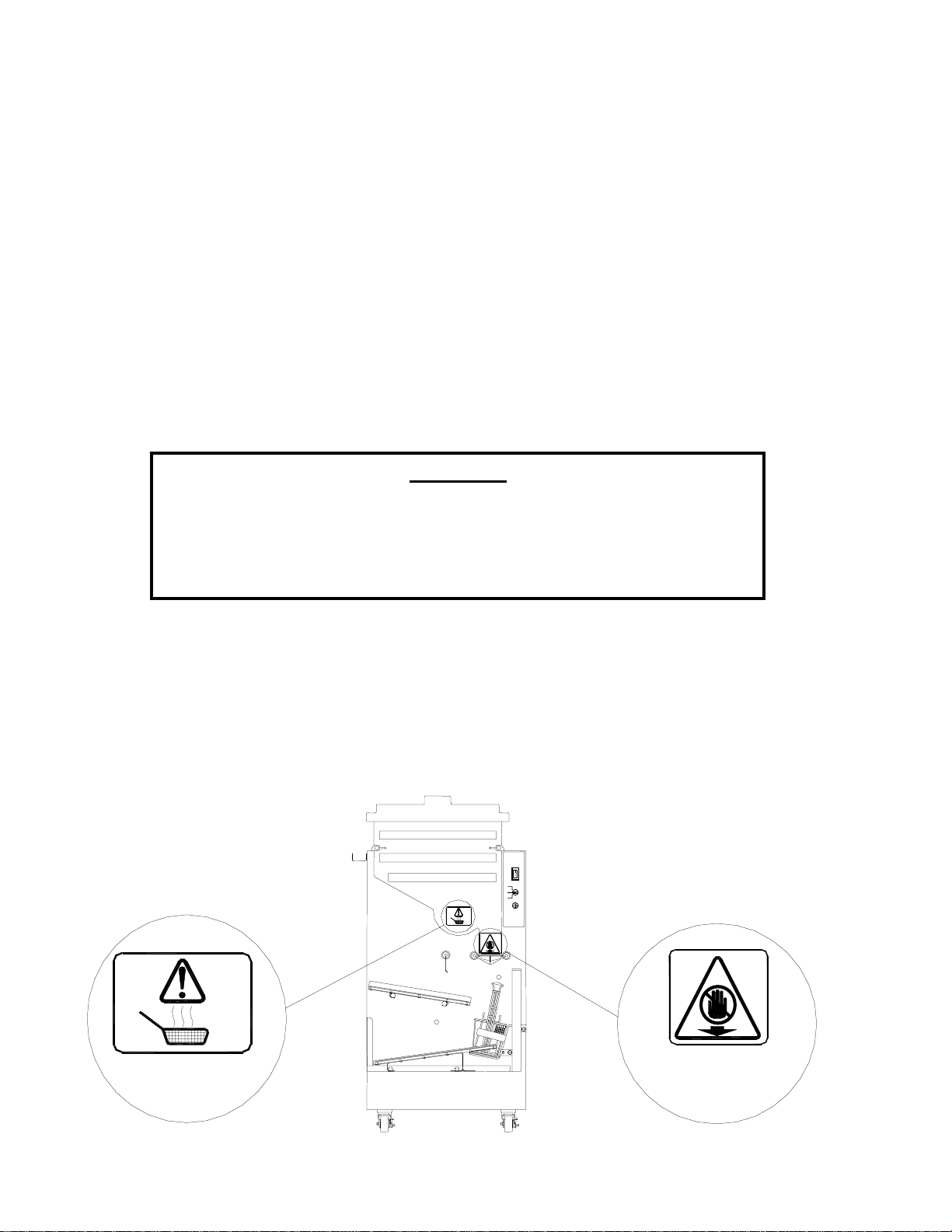
INTERNATIONAL SAFETY LABELING
International Safety Labeling is represented with the symbols illustrated below. The labels are affixed to the
Hopper to clearly indicate areas that could be harmful to the operator of the Dispenser.
These safety issues are:
1. BASKETS MAY BE HOT: Baskets should always be picked up by the provided handle.
2. NO HANDS BELOW: Hands should not be placed near or below the Accumulator Doors while the
Dispenser is energized.
BASKETS MAY BE
HOT
NO HANDS BELOW
Copyright © 2005 Automated Equipment LLC. All Rights Reserved
6
Page 7
GDF28 Dispenser
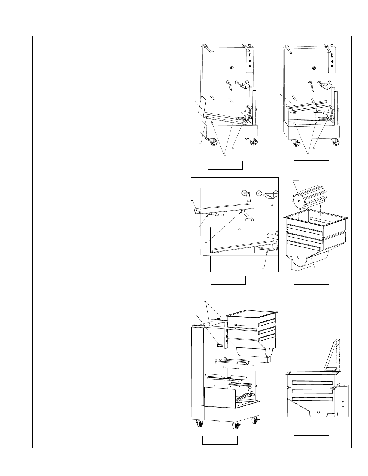
ASSEMBLING THE DISPENSER
INSTALL DRIP TRAY (Fig. 1)
• Position the Drip Tray with the Basket Stop away from
the Lift Saddle as shown.
• Slide the end of the Drip Tray under the Lift Saddle.
• Line up the holes in the Drip Tray with the Locator
Pins and set the Drip Tray down over the Locator
Pins.
INSTALL LOWER GUIDE (Fig. 2)
• Position the Lower Guide with the high end toward the
Lift Saddle. The low end should be toward the Basket
Stop as shown.
• Line up the holes in the Lower Guide with the Locator
Pins and set the Lower Guide down over the Locator
Pins.
INSTALL UPPER GUIDE (Fig. 3)
• Locate the Hooked Tab and the Straight Tab on the
bottom of the Upper Guide.
• Position the Upper Guide with the Hooked Tab away
from the Lift (as shown). Tilt the Upper Guide back
so that the end near the Lift is two to three inches (510cm) higher than the end with the hooked tab.
• Place the Hooked Tab of the Upper Guide around the
LEFT Guide Support . Align the slot in the Hooked
Tab with the screw in the middle of the Guide
Support, then slide the Upper Guide to the RIGHT,
hooking it on the LEFT Guide Support.
• Align the slot in the straight tab of the Upper Guide
with the screw on the RIGHT Guide Support. Press
the upper guide down, snapping it into place.
INSTALL THE HOPPER AND DRUM (Fig. 4 & 5)
• Find the square opening in one end of the Dispenser
Drum.
• Place the Dispenser Drum in the Hopper, aligning the
square opening on the Dispenser Drum with the hole
in the back of the Hopper.
• Grasp the Hopper so that the hole is toward the
Dispenser.
• Align the indentations on the Hopper with the Hopper
Support Bars.
• Push the Hopper forward onto the Hopper Support
Bars until the Drum Motor shaft touches the
Dispenser Drum.
CAUTION: Do NOT force the Hopper back; this could
damage the Hopper or Drum.
• Rotate the Dispenser Drum (CLOCKWISE or
COUNTER-CLOCKWISE) while applying gentle
pressure to the Hopper until you can easily slide the
Hopper fully onto the Hopper Support Bars.
• Lock the Hopper onto the Dispenser by pressing the
Locking Pins on the ends of the Hopper Support Bars
towards each other.
PLACE THE DIVERTER IN THE HOPPER (Fig. 6)
Be sure that it is hooked over the RIGHT edge of the
Hopper.
PLACE THE HOPPER LID ON THE HOPPER (Not
pictured)
Hook the lid's tab over the back rim of the Hopper,
then set the Lid down.
LOWER
BASKET
DRIP
LIFT SADDLE
LOCATOR PINS
FIGURE 1
FIGURE 2
LIFT SADDLE
LOCATOR PINS
DISPENSER DRUM
UPPER
GUIDE
HOOKED
TAB
STRAIGHT
TAB
SUPPORT
DRUM
MOTOR
SHAFT
BARS
LIFT SADDLE
FIGURE 3
FIGURE 4
DIVERTER
HOPPER
FIGURE 5
Copyright © 2005 Automated Equipment LLC. All Rights Reserved
7
FIGURE 6
Page 8

GDF28 Dispenser
DAILY SET-UP
1. Verify that the Power Switch is in the OFF position.
2. Plug the Power Cord into a wall outlet.
3. Load the Hopper with frozen french fries. DO NOT
SHAKE OR DROP the fries into the Hopper (refer to
"LOADING THE HOPPER", page 8).
4. Turn the Load Select Switch to the desired load weight.
5. Fill the Upper Guide with empty Custom Baskets.
6. Turn the Power Switch to the ON position (illuminated).
Electric motors will orient themselves to starting positions
and the dispenser will initiate the filling process.
7. Use filled Baskets from the Lower Guide for Fry
production.
8. Return empty Baskets to the Upper Guide for refilling after
the cooking cycle is complete.
LOADING THE HOPPER
To achieve optimum fry yield and the most consistent basket
loads, it is important to use the following technique for loading
frozen fries into the hopper. Depending on your fry supplier, you
will receive your french fries packaged in boxes of six pounds
each, or bags of six pounds each. These bags or boxes will be
packed six to a case. The hopper will accept one full case plus
one bag or box of french fries (42 lbs. or 19 kg).
For each bag or box of french fries:
1. Remove the bag or box of french fries from the case. Be
careful not to crush the fries.
2. Open the top of the bag or box completely.
NOTE: If your supplier uses bags, be careful that the top is
fully open. If it is partially open, the bag may retain fries.
3. Hold the opened end of the box or bag closed with your
hand and lay it in the hopper with the opening toward the
side opposite of the diverter.
4. Release the opened end of the bag or box.
5. Empty the bag or box into the hopper by pulling it evenly
toward the Diverter. When adding multiple bags of fries,
alternate the placement of the bag or box in the hopper
opposite of the previous bag or box. The second bag of
fries should be emptied into the Hopper with the opening
toward the Diverter, and pulling it evenly toward the
Hopper Wall opposite the Diverter.
NOTE: This criss-cross loading method assures an even
distribution of fry lengths in the Hopper and the Baskets.
NOTE: Do NOT shake or drop fries from the bag or box
into the Hopper.
NOTE: If the loading is done correctly, you should be able
to leave a uniform layer of fries in the hopper by simply
pulling the bag or box across the hopper and then out of
the hopper.
6. Repeat steps 1 through 5 until the hopper is full.
NOTE: Do NOT fill the hopper past the top.
7. Close the lid on the hopper by engaging the hook at the
back of the hopper, and setting the lid down
DAILY CLOSING
1. Turn the Power Switch to the OFF position.
2. Remove all Baskets from the upper and Lower Guides.
Discard and record the uncooked fries.
NOTE: During the last few hours of the day, you may
want to keep only two or three bags of french fries in the
hopper and run the dispenser in SINGLE mode, to
minimize waste.
3. Remove the Hopper Lid by lifting it UP and BACK to
unhook the tab.
4. Hang the hopper lid on the front of the hopper, by
hooking the tab on the lip of the hopper.
5. Discard and record any fries remaining in the Hopper at
closing.
6. Check that the Accumulator Doors are empty of fries.
7. Disconnect the Power Cord from the electrical outlet
8. Remove the Diverter by grasping it and pulling it UP.
9. Slide the Locking Pins outward to release the Hopper.
10. Remove the Hopper (and the Dispenser Drum inside) by
pulling the Hopper OUT and AWAY from the Hopper
Support Bars.
11. Remove the Upper Guide assembly by lifting the RIGHT
end and sliding it to the LEFT.
12. Remove the Lower Guide by lifting it straight UP.
13. Remove the Drip Tray by lifting it from the Basket Stop
end and sliding it from under the saddle.
14. Take the hardware removed from the Dispenser to the
back sink. Wash it in a hot solution of McD APSC (HCS),
rinse with clear water, sanitize and allow to air dry.
15. Roll the dispenser out from the wall, so that you can
clean behind it and underneath it.
NOTE: Do NOT roll the dispenser to the back sink for
cleaning, this will cause unnecessary wear on the
dispenser and possible premature failure.
16. Wipe down the dispenser with a hot solution of McD
APSC (HCS) and water. Repeat wipe-down with clear
water, sanitize and allow to air dry.
NOTE: DO NOT SPRAY DOWN THE DISPENSER. It is
not sealed against jetting water and contamination may
get into sensitive components. SPRAYING MAY VOID
THE WARRANTY!
17. Reassemble the dispenser.
18. Roll the dispenser back into place.
WARNING
PINCH HAZARD
Personnel should take care not to place hands or fingers near the Drum inside the Hopper, while this machine is
in operation. Hands or fingers could be pinched between the Drum and the Hopper as the Drum turns.
Copyright © 2005 Automated Equipment LLC. All Rights Reserved
8
Page 9
GDF28 Dispenser
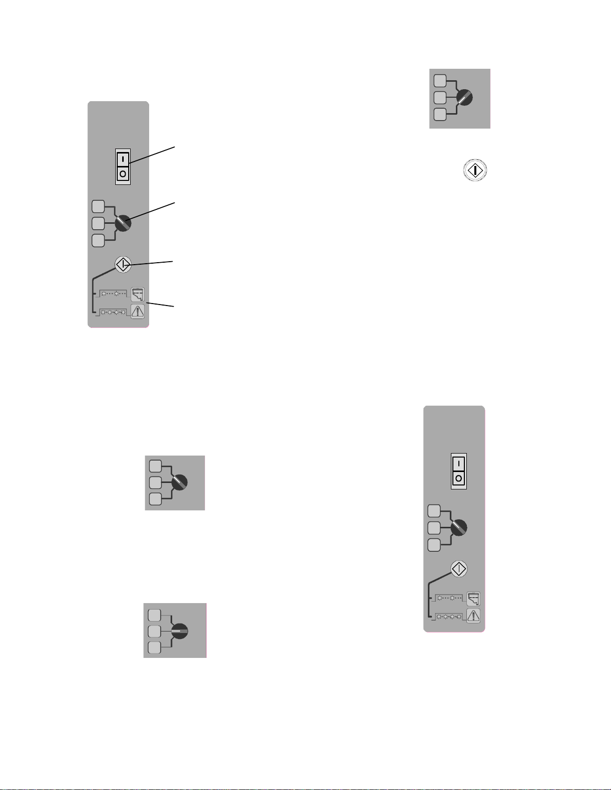
OPERATOR CONTROLS
The following switches and buttons are located on the
Operator Panel:
GDF28
Power Switch
1
2
3
Position #3: For Automatic dispensing of 1.5 lb./700
gm Basket Loads.
1
Load Select Switch
2
3
Start/Reset Button
Warning/Error
Light Symbols
Power Switch (Orange)
The Power Switch supplies electrical power to the
Dispenser. It illuminates when the Dispenser has
power. The Power Switch also functions as a circuit
breaker for the machine.
LOAD SELECT SWITCH
The Load Select Switch has 3 positions that allow the
operator to select Basket Load weights and control
operation.
1
2
3
Position #1: Single basket loading. Press the
Start/Reset Button to dispense a single basket of Fries.
Pre-set to .75 lb./350 gm/Single mode.
NOTE: International units are factory set to automatic
mode. US and Canadian units are factory set to single
mode. This can be reconfigured by performing function
#6 (see page Error! Bookmark not defined. & 13).
Start/Reset Button (Green)
Press to start the loading of a single Basket if the Load
Select Switch is set for Position #1 (0.75 lb./350gm).
Press to reset a System Error or an empty Hopper
warning.
The symbols below the button provide an explanation
of warning and error conditions.
A slow blink (about 1 per second) of the Start/Reset
Button indicates either an empty Hopper or bridged
appetizers.
A fast blink (about 5 per second) of the Start/Reset
Button indicates a system error.
CALIBRATE WEIGHT SENSOR
For optimum performance, the weighing system should
be calibrated once per year. US Dispensers will need
two 1lb weights (eight ¼ lb hamburger patties will
work). International Dispensers should use two 450gm
weights. To calibrate, follow these steps:
GDF28
1
2
3
1
2
3
Position #2: Automatic dispensing of 1.0 lb./450 gm
Basket Loads.
Copyright © 2005 Automated Equipment LLC. All Rights Reserved
1. Turn the Dispenser OFF ( O ). Wait 15 seconds
2. Remove the Hopper and Drum to gain access to
the top of the Accumulator doors.
3. Place Selector Switch in Position 1.
4. While holding the Start / Reset Button in, Power the
Dispenser ON ( I ).
9
Page 10

GDF28 Dispenser
5. Continue holding the Start / Reset Button in until
the Green Light flashes rapidly, and then release.
6. Place an empty Basket on the Upper Guide. Any
product remaining on the Accumulator doors will be
dispensed into the Basket before calibration continues.
After dispensing, the Green light will stop flashing.
7. Place the Selector Switch in Position 2. The Green
Light will begin to flash again.
8. Place 1.0 lb. (450gm) On the Accumulator Doors.
9. When the Dispenser has reached a stable value,
the Green Light will stop flashing.
10. Place the Selector Switch in Position 3. The green
Light will begin to flash.
11. Place an additional 1.0 lb. (450gm) On the
Accumulator Doors, for a total of 2 lbs (900gm).
12. When the Dispenser has reached a stable value,
the Green Light will stop flashing.
13. Turn the power OFF ( O ).
14. Remove the weight from the Accumulator Doors.
15. Replace the Hopper and Drum
16. Place the Selector Switch in the desired Basket
size position.
17. Power the Dispenser ON ( I ).
18. The Green Light will illuminate indicating the
Dispenser is ready for Normal Operation.
FRONT PANEL OPERATIONS
CUSTOMIZATION (Bypass Mode)
Bypass Mode will allow the dispenser to remain
functional in the event the weighing system or the
basket sensors fail.
NOTE: The BYPASS mode has two methods of
operation and the Dispenser will automatically select
the appropriate method.
Method 1:
GDF28
1
2
3
To Engage the BYPASS Mode of operation:
• Turn the Dispenser off. Wait 15 seconds.
• Select Position #2.
• Hold in the Start/Reset Button
• While holding in the Start/Reset Button, turn the
Dispenser power ON ( I ). Double flashing of the
Start/Reset button indicates BYPASS
This modification to the Dispenser operation is temporary:
When the Dispenser power is turned OFF ( O ), the
Dispenser resets to normal operations when the power is
turned ON ( I ) again.
NOTE: Allow 15 seconds before turning the Dispenser
Power Switch ON ( I ) after being turned OFF ( O ).
NOTE: The Bypass mode will significantly slow down the
operations of the Dispenser. The Start/Reset button has
to be used in either mode of Bypass operation.
The Dispenser detects a functioning Weight
Sensor.
The Dispenser will appear to operate normally, filling
the accumulator with the correct weight of appetizers.
The Start/Reset button must be pushed to dispense the
appetizers into a basket. This method allows the
Dispenser to operate with faulty basket sensors.
Method 2:
The Dispenser detects a failed Weight Sensor.
Holding in the Start/Reset Button, the Drum will turn to
dispense appetizers onto the Accumulator Doors.
Releasing the Start/Reset Button stops the Drum
motor, opens the Accumulator doors, closes the
Stopgate, and then lowers the filled Basket.
After lowering the Basket, the Lift Saddle will come
back up and the Stopgate will open to allow the next
Basket to move into the Lift Saddle for filling.
Copyright © 2005 Automated Equipment LLC. All Rights Reserved
10
Page 11

GDF28 Dispenser
SEQUENCE OF OPERATION
Initial Power Up
The chart below is an example of the Dispenser’s sequence of operations under the following conditions:
• The Hopper is fully loaded with french fries and properly installed on the Dispenser.
• There are 2 empty Baskets on the Upper Guide.
• There are no empty Baskets on the Lower Guide.
• The Dispenser Load Switch is in the 1.0 lb./450 gm position.
NOTE: The time for one basketing cycle is approximately 4 - 6 seconds.
Event Response
Power Switch Turned ON
Dispensing Begins.
Stopgate opens. When the weight is attained the Stopgate opens to allow a Basket to slide into the Lift
Accumulator doors open
and empty.
Stopgate Closes The Stopgate closes to allow clearance of the filled Basket in the Lift Saddle.
Lift Saddle lowers Basket. The Lift Saddle lowers the filled Basket to the Lower Guide.
Accumulator Doors close.
Lift Saddle raises up.
Stopgate opens. Stopgate opens to allow the next empty Basket to slide into the Lift Saddle.
Restart of Dispensing.
Stopgate moves to the home position.
The Lift moves to the home position, pauses, then raises to the up position.
The Drum turns and fries are dispensed from the Hopper to the Accumulator Doors.
The Accumulator Doors weigh the fries and signal to stop the Drum Motor when the
1.0 lb. (450 gm) weight is attained.
Saddle.
A sensor in the chassis of the Dispenser detects the Basket. If a Basket is not present,
the Dispenser will wait until it detects the Basket.
When the Basket is present, the Accumulator Doors open to dispense the fries into the
Basket.
As the Basket slides down the Lower Guide, another sensor detects the Basket
arriving on the Lower Guide..
The Accumulator Doors close and the Lift Saddle raises to the up position.
Cycle starts over again. Dispensing Begins
After filling the second Basket, the Dispenser will stop because there will not be a
Basket detected in the Lift Saddle.
Copyright © 2005 Automated Equipment LLC. All Rights Reserved
11
Page 12

GDF28 Dispenser
FUNCTION LIST
The following is a complete list of the available functions.
Number
Function Name Description
1 restart function Same as Start/Reset Button on front panel.
2 display last error Displays the last error number recorded.
3 weigh disable Turns the weighing cycle on and off.
4 tare function Not used.
5 calibrate Accepts 16oz (450gm) and 32 oz. (900 gm) reference weights; sets the 12 oz.
(350 gm) and, 16 oz. (450 gm), and 24 oz. (700 gm) targets.
6 adjust_Pos1 Programs selector switch position 1: (Default: 12 0z./350 gm, Manual, Single
Load).
Sub-Function 1 - Increases weight setting.
Sub-Function 2 - Decreases weight setting.
Sub-Function 3 - Sets “SL” (single load) or “AU” (automatic dispense)
Sub-Function 4 - Sets “1” (single) or “2” (double) Load
Sub-Function 5 - Closes F6 Sub-Functions.
7 adjust_Pos2 Programs selector switch position 2 (Default:16 0z./450 gm, Automatic, Single
Load). Sub-Functions same as Function 6.
8 adjust_Pos3 Programs selector switch position 3 (Default:24 0z./700 gm, Automatic, Single
Load). Sub-Functions same as Function 6.
9 not used
10 watchdog test Generates a signal to the program so that the watchdog timer fires. Invokes
error #8 (not displayed).
11 weight sensor readout Displays the current reading from the weight sensor (live display).
12 actuate lift Moves the lift up and down. Displays the Lift position counts (position of the lift).
13 actuate doors Opens and closes the accumulator doors.
14 actuate stopgate Opens and closes the stopgate.
15 actuate drum Turns the drum motor on and off. Displays speed (16 … 0), varies with each
press of the Enter button.
16 actuate light Turns the restart light on and off.
17 restore defaults Clears the error log, sets default weighing parameters, defaults lift counts to 102.
18 clear errors Clears the error log.
19 error counts Displays the error log.
20 parameters Always displays default values.
21 not used
22 not used
23 not used
24 bypass mode Enables the dispenser to run in “Bypass”, single mode. Ignores select system
errors.
25 set units Sets weighing units to ounces “US”, or grams “In” International.
26 exercise mode Enables exercise mode, all motor functions cycle.
27 rev Displays revision level of installed EPROM
28 segment test The segments will illuminate in a moving display mode.
29 lift up counts Displays Lift Up position counts. Default range is from 77 (bottom) to 179 (top).
30 adjust lift down Decreases the Lift Up position, 1 count = 1/12” (2.1 mm). Number of counts is
displayed.
31 adjust lift up Increases the Lift Up position, 1 count = 1/12” (2.1 mm). 105 counts maximum.
Number of counts is displayed.
Copyright © 2005 Automated Equipment LLC. All Rights Reserved
12
Page 13
CONTROLLER FUNCTIONS
GDF28 Dispenser
In the back of the Dispenser, in the upper right corner
of the controller circuit board is the service interface.
This is used to adjust the basket load sizes and to test
and adjust the operation of the Dispenser.
Select Button
The following sections discuss the modes of this
display:
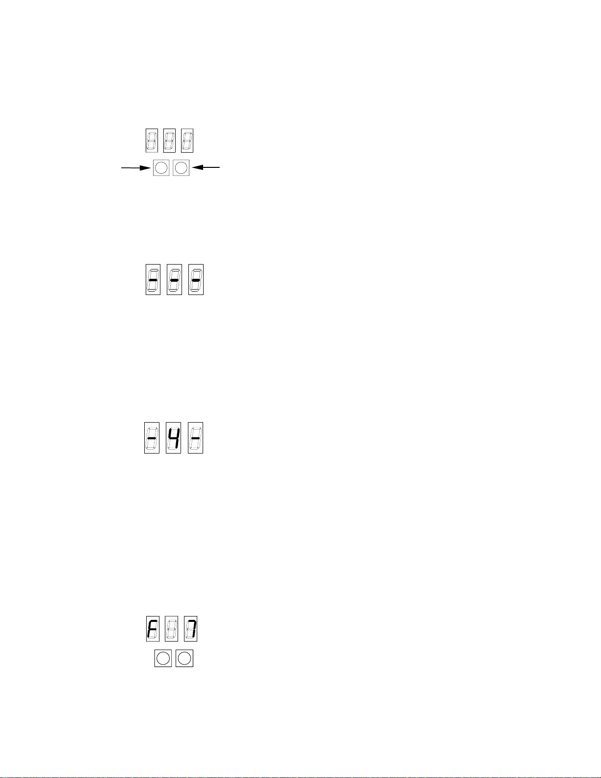
Normal Operation
During Normal Operation, the display will show a series
of horizontal bars, as shown below.
Error Conditions
When an error occurs, the Start/Reset Button will flash
rapidly (5 times per second) and the Lift Saddle will go
down. Normally, an error condition can be cleared by
pressing the Start/Reset Button. If an error persists or
occurs too often, you may need to know what error is
occurring. For this purpose, when an error occurs, the
center line of the display is replaced with an error code.
The example below is displaying error code 4.
A complete list of the error codes is given in the
troubleshooting section (See page 25).
The controller has several functions that may be used
to adjust and test the functions of the Dispenser.
These are accessed using the following procedure.
1. Press the Select Button the number of times as the
function number desired. Each time you press the
Select Button the display will show the function code
for the function that is ready. The example below
shows Function 7: (Adjust Basket Weight, Switch
Position #2, DOWN.)
Enter Butt on
2. When the display shows the desired function number,
press the Enter Button to activate the function.
What happens next depends on the function selected.
Pressing the Select Button will close the function;
pressing the Enter Button will advance the function to the
next step. The following is a detailed account of each
function.
Function 1 – Restart
Returns immediately to the normal display. This function
serves the same purpose as the Start/Reset button on
the front panel.
Function 2 - Display Last Error
Displays the last error number recorded. This allows the
Dispenser to be restarted after an error, and then find
out what the error was while the Dispenser is in service.
Function 3 - Disable Weighing
Turns the weighing process on and off. This is used for
testing of the mechanical systems. It allows you to work
on the dispenser without weighing fries. This is a
temporary setting and will automatically reset on power
up.
Function 4 – Not Used (NCWS)
Function 5 – Calibrate (NCWS)
Displays the word “CAL” on the display. Verify the doors
are empty and press the ENTER button: the display will
respond “C1.0.” Place 1.0 lb./ 16 ounces / 450 gm. on
the door, wait 10 seconds and press the ENTER button:
the display will respond “C2.0.” Place 2.0 lbs. / 32
ounces / 900 gm. on the door, wait 10 seconds and
press the ENTER button: the display will return to the
normal “- - -.“ Remove the weights. The unit is now
calibrated. When finished, turn machine off, wait 15
seconds, turn machine back on.
Function 6 - Load Select Button #1
(Default: US 12 0z, Manual, Single Load
International 0.350kg, Automatic, Single Load)
Press ENTER to enter the first Sub-Function:
Sub-Function 1 - Increases weight setting (1oz/.025kg).
Display reads the current weight setting (default is US
12 / IN .35).
Successive activation of the ENTER button increases
the value (13, 14, 15, etc. / .37, .40, .42, etc.).
Pressing the SELECT button again, closes this SubFunction and advances to the next F6 Sub-Function:
SELECT
NOTE: If you leave the display in this mode, it will
return to Normal Operation after a few seconds. This is
a safety feature, to prevent functions from being
selected by accident.
Copyright © 2005 Automated Equipment LLC. All Rights Reserved
ENTER
Sub-Function 2 - Decreases weight setting
(1oz/.025kg).
Display reads the current weight setting, preceded by a
minus sign (default is -12 / -.35).
Successive activation of the ENTER button decreases
the value (-11, -10, -09, etc. / -.32, -.30, -.27, etc.).
Pressing the SELECT button again closes this SubFunction and advances to the next F6 Sub-Function:
Sub-Function 3 - Sets “SL” (single load) or “AU”
(automatic dispense). The default is “SL”.
13
Page 14

GDF28 Dispenser
Successive activation of the ENTER button toggles the
display between “SL” and AU”.
Pressing the SELECT button again closes this SubFunction and advances to the next F6 Sub-Function.
Note: Two dispense cycles are needed before the
change from Automatic to Manual takes effect.
Sub-Function 4 - Sets “1” (single) or “2” (double) load.
Display reads “1” or “2”.
Successive activation of the ENTER button toggles the
value between “1” (single) and “2” (double) load.
Pressing the SELECT button again, closes this SubFunction and advances to the next F6 Sub-Function:
Sub-Function 5 - Closes F6 Sub-Functions.
Display reads “END” (end of available Sub-Functions).
Pressing the ENTER button closes the F6 functions.
OR
Pressing the SELECT button, will result in a return to
Sub-Function 1.
Function 7 -Program Switch Position 2
(Default: US 16 0z, Automatic, Single Load
International 0.450kg, Automatic, Single Load)
Programs switch position 2. Functions are the same as
for Switch Position 1 (Function 6).
Function 8 - Adjust Switch Position 3
(Default: US 24 0z, Automatic, Single Load
International 0.700kg, Automatic, Single Load)
Programs switch position 3. Functions are the same as
for Switch Position 1 (Function 6).
Function 9 -NOT USED
Function 10 - Watchdog Test
Causes an Error 8.
Function 11 – Weight Sensor Readout (NCWS)
Displays the current weight sensor reading and is used
to test the weight sensor. This is a live display,
changing constantly with the weight sensor input. Use
function 11 to check the operation of the weight sensor.
Applying 1 lb./450gm of weight to the accumulator
doors will cause a deflection of approximately 100
counts to the readout. Press the Select button to close
the function. NCWS tare should be 30 (+/-9).
Function 12 - Actuate Lift Saddle
The display shows the live lift position. Each time the
Enter Button is pressed, the controller will change the
state and direction of motion for the circuitry that drives
the Lift Saddle. If the Lift Saddle is down, it will go up. If
it is up, it will go down. Press the Select button to close
the function.
Function 13 - Actuate Doors
Display remains “F13”. Each time the Enter Button is
pressed, the controller will activate the Accumulator
Doors for one cycle. They will open or close. Press the
Select button to close the function.
Function 14 - Actuate Stopgate
Display remains “F14”. Each time the Enter Button is
pressed, the controller will change the state and
direction of motion for the circuitry that drives the
Stopgate. If the Stopgate is open, it will close. If the
Stopgate is closed, it will open. Press the Select button
to close the function.
Function 15 - Actuate Drum
The display shows the drum speed (16: fastest, 0:
slowest). Each time the Enter Button is pressed, the
controller will change the speed (16……0 -16) of the
Dispenser Drum. This function is used to test the Drum
Motor. Press the Select button to close the function.
Function 16 - Actuate Light
Display remains “F16”. Each time the Enter button is
pressed, the controller will change the state of the output
that drives the Start/Reset Light. If it is off it will turn it on.
If it is on it will turn it off. This function is used to test the
Start/Reset Light. Press the Select button to close the
function.
Function 17 - Restore Defaults
This function clears the error log, and restores the
weighing parameters and lift height values to factory
defaults. Calibration and lift height must be
reprogrammed.
NOTE: Function 17 will reset Int'l units to US units.
Function 25 can be performed to return to "Int'l" status.
Function 18 - Clear Errors
This function resets the counts in the error log to zero.
We recommend that this be done periodically to prevent
records of occasional errors from building up (even a
perfectly running dispenser will get occasional errors
from improper handling) and confusing a service tech at
a time when the error log could be useful.
Function 19 - Error Counts
Displays the word “Err”. Each time the Enter Button is
pressed, it moves to the next error count. When the last
count is passed, the display returns to normal mode.
The error counts are displayed in numerical order. Error
number 9 is not included (error number 9 indicates a
memory failure, and therefore renders any history
meaningless). For example, if you saw this sequence of
displays:
“Err”
“1. 0”
“2. 0”
“3. 1”
“4. 3”
“5. 2”
“6. 0”
“7. 21”
“8. 0”
This would indicate that, since the last time the errors
were cleared, there had been one error 3, 3 error 4’s, 2
error 5’s, and 21 error 7’s.
Copyright © 2005 Automated Equipment LLC. All Rights Reserved
14
Page 15

GDF28 Dispenser
Function 20 - Parameters
Displays the word “Con”. Each time the Enter button is
pressed, it moves to the next weighing parameter.
When all parameters have been displayed, the display
returns to the normal mode.
The weighing parameters are (in order of appearance):
1. Switch position #1 target - the number of digitizer
steps that represents .75lbs/12 oz./350gm. The
default value is 75 US / 70 INTL (NCWS).
2. Switch position #2 target - the number of digitizer
steps that represents 1.0lb/16 oz./450gm. The
default value is 100 US / 90 INTL (NCWS).
3. Switch position #3 target - the number of digitizer
steps that represents 1.5lb/24 oz./700gm.The
default value is 150 US / 140 INTL (NCWS).
If the loads have been adjusted, these may be slightly
different. The tare value after calibration should be
approximately 30 (+/- 9). For details, see the section
on operation/ calibration of the weight sensor. (NCWS)
Function 21 – Not Used
Function 22 – Not Used
Function 23 – Not Used
Function 24 - Bypass Mode Enable (volatile setting)
Entering this function the display will read either “nor,”
(normal) Bypass mode disabled, or “bYP”, Bypass
mode enabled. BYPASS mode allows the machine to
run in single mode when an optical sensor has failed.
The “BYPASS” mode has two methods of operation:
Method 1:
The Dispenser detects a functioning Weight
Sensor. When the Start/Reset Button is pressed, the
Dispenser utilizes the Weight Sensor to determine the
weight of the frozen appetizers. The Dispenser will
appear to cycle normally, ignoring other system errors.
NOTE: Bypass Mode is significantly slower than normal
operation.
NOTE: All settings function in single basket operation
while in Bypass Mode.
Method 2:
The Dispenser detects a failed Weight Sensor.
Holding in the Start/Reset Button, the Drum will turn to
dispense frozen appetizers onto the Accumulator
Doors. Releasing the Start/Reset Button stops the
Drum motor, opens the Accumulator Doors closes the
Stopgate, and lowers the filled Basket.
After lowering the Basket, the Lift Saddle will come
back up and the Stopgate will open to allow the next
Basket to move into the Lift Saddle for filling.
The Bypass Mode is further identified by double
flashing of the reset button.
NOTE: The Bypass mode will significantly slow down
the operations of the Dispenser. The Start/Reset button
has to be used in either mode of Bypass operation.
Entering this function permits selection of ounces or
grams as the weighing units. Pressing the enter button
will toggle the display between ounces “US” and grams
“In” (international) for the weight units. Pressing the
Select Button sets the displayed weight units for
dispenser operations. The weight sensor should be
calibrated after changing this setting.
Function 26 - Exercise Mode (volatile setting).
When the dispenser is in the exercise mode, all systems
will continuously cycle. The exercise mode is designed
to “break in” a replaced component. The exercise mode
is volatile and will reset when the dispenser power is
turned off.
Function 27 - Display EPROM Revision Level.
The readout will display the revision level of the installed
EPROM.
Function 28 - Segment Test
Verifies that all display segments are functional. The
segments will illuminate in a moving display mode.
Function 29 - Lift Position Counts
The readout will display the encoder counts for the lift
and will change as the lift travels up or down. Default is
77 at the bottom of travel and 179 at the top of travel.
Function 30 - Adjust Lift Down
The readout will display the current or default value for
the Lift height (102). Each time the Enter button is
pressed, this value will decrease by 1, or approximately
1/12” (2.1 mm). The Select button must be pushed after
lowering the lift height to complete the change. The new
height setting will take effect on the next lift cycle.
Function 31 - Adjust Lift Up
The readout will display the current or default value for
the Lift height (102). Each time the Enter button is
pressed, this value will increase by 1, or approximately
1/12” (2.1 mm). The Select button must be pushed after
raising the lift height to complete the change. The lift will
raise slightly each time the count is incremented.
NOTE: Do not adjust the lift height to compensate for
bent saddle/shoulder screws. Maximum recommended
lift height is 105. An adjustment of 106 and higher may
result in damage to the controller PCB.
Function 25 - Select Weight Units “US” or “In”
Copyright © 2005 Automated Equipment LLC. All Rights Reserved
15
Page 16

GDF28 Dispenser
ERROR CODES
The status of the Dispenser is displayed on the Start/Reset Button light. When the Hopper is filled and operating
automatically, the Start/Reset Button remains steadily illuminated. When a System Error occurs, the Start/Reset
button flashes rapidly (about 5 per second). System Errors are a result of incorrectly assembling the Dispenser, or
an interruption in the normal operation. System Errors are also displayed inside the Dispenser on the controller
PCB. Each error has its own error code; these are summarized below.
Number Error Name Definition
Error #1 ACCUMULATOR TIME-
OUT
Error #2 LIFT MOTION
Error #3 STOPGATE MOTION
Error #4 LIFT SENSOR
Error #5 GUIDE SENSOR
Error #6 Not Used
Error #7 ENCODER
SEQUENCE
Error #8 ABNORMAL RESET
(WATCHDOG)
Error #9 NVRAM CHECKSUM
Accumulator Home Switch fails to turn off within 0.6 seconds of the motor
being turned on, or it fails to turn on within 5.0 seconds of the motor output
starting. Error will occur if the motor or home switch is disconnected,
obstructed, broken, or the associated input or output on the controller PCB
has failed.
Error will occur if the motor or encoder inputs are disconnected, or the
associated input or output on the controller PCB has failed. Error will occur if
there is a physical obstruction of Lift Saddle or damage to Lift Saddle
components. Error will occur if there is a Failure of lift drive motor w/ gear
box, lift tube, encoder, or encoder disk.
The stop gate allows 1.0 second to home itself. Error will occur if the motor
or home switch is disconnected, obstructed, broken, or the associated input
or output on the controller PCB has failed, or if the Hardstop screw is broken
off.
The controller PCB has sent the Lift Saddle down and the controller PCB is
still receiving the Lift sensor input. Sensor is operating out of sequence.
The controller PCB has not received a signal from the guide sensor after the
Lift is down. The Guide Sensor has failed to detect a Basket leaving the Lift
Saddle.
This is caused by both of the encoder sensors changing at the same time. If
the count rate of the encoder exceeds 100 counts per second (normal speed
is 51 counts) or something electrically interferes with the encoder sensors,
the error would occur. This error could also be caused by contamination.
An event other than a normal power up has caused the processor to restart.
This could be a watchdog reset, (indicating that the processor has hung or
Function 10 was entered), a processor reset (an EMI/RFI problem), or the
processor has detected corrupted memory. NOTE: Error code #8 is not
displayed.
The processor writes the permanent data (error logs, configuration, and
operating parameters) along with extra data that it uses to verify the data is
valid. Data may be invalid for several reasons:
a) The first time the controller PCB has been used.
b) Software upgrade. (When new software has a different memory
configuration).
c) Power down interrupted a Non Volatile RAM write cycle. The write
cycle usually happens when the reset button is pressed to reset an
error.
d) The NVRAM has failed
Copyright © 2005 Automated Equipment LLC. All Rights Reserved
16
Page 17

GDF28 Dispenser
NOTE:
- All "L" numbers refer to numbered LEDs on the controller board. (see Page 29 & 30)
- All "F" numbers refer to controller functions. (see Page 13)
ERROR 1
Do
Accumulator
NO
doors open?
Does L11
come on?
NO
Go to F13 and
see if L11 will
come on when
enter is toggled. If
not, replace
controller and
correct version of
eprom.
YES
Does L7
come on
when the
doors open?
YES
Make sure
the cam
follower Hblock screw is
tight on the
left door shaft
(left from the
front)
NO
Check the
accumulator
home switch
wiring and
operation, L7
should blink
on when
switch is
acitvated.
YES
Does the
motor make
noise?
YES
Check the
white cam on
the motor
shaft, not
loose or
broken. Check
home switch.
NO
Check wires to
accumulator
motor (M2) and
to control board.
Copyright © 2005 Automated Equipment LLC. All Rights Reserved
17
Page 18

NO
Check wiring
connections at
motor and at output
#1, terminals 5 and
6 on controller
board. Also check
board for corrosion.
Remove lift
tube and press
reset, does
motor run?
NO
Remove lift motor wires
5,6 on input one, and
hot-wire to the 24v input
plug by touching the
wires on the screws.
Does the motor
spin both
directions?
(Reverse wiring)
NO
Replace the lift
drive motor
290147
ERROR 2
Does the lift move
at power up?
Should go down
first, unless
already there.
Check lift tube,
YES
should move
smoothly. If
not, replace or
clean/relube it.
Replace the
YES
controller board,
290626. Verify
proper software.
GDF28 Dispenser
YES
Does the lift
move both
directions, or
just one way?
Check for water
damage to
controller board
and plugs.
Replace
controller
290626, and
appropriate
version of
software.
ONE
BOTH
Check the
saddle for
binding. Check
lift height setting
(F30), not to
exceed 106.
Remove lift
tube, check for
binding. Check
lift motor for
water damage.
With lift tube out,
and while still in a
system error,
manually verify
encoder operation.
Using a flat blade
screwdriver, place
blade inside center
of motor next to the
center pin. Be
careful not to
damage encoder
disk/vane. Turn the
handle either
direction. L4/5
should go on/off
completely, but
never change at the
same time. Also
check encoder
disk/vane for
damage. Replace
both encoders or
disk/vane as
needed.
Copyright © 2005 Automated Equipment LLC. All Rights Reserved
18
Page 19

GDF28 Dispenser
ERROR 3
YES
L6 should be
ON when stop
gate is fully
open or closed,
OFF when gate
is anywhere in
between.
YES
Does it
move BOTH
directions?
Does the
stop gate
move at all?
NO
Verify wiring to
motor and
control board.
Replace the
stop-gate motor.
Verify that L22
comes on as gate
closes, L23 as
gate opens. If not,
replace control
board 290626 and
appropriate
software.
YES
NO
Does
L22/23
come on?
NO
Go to F14, L22/23
should toggle
on/off as the
enter button is
pressed, if not,
replace control
board 290626
and appropriate
software.
Does L6
NO
operate
properly?
YES
Assure hard-stop
screw is present.
Rotate stop gate
manually clockwise,
should not be able to
rotate past the
7 o-clock position.
Copyright © 2005 Automated Equipment LLC. All Rights Reserved
Check encoder
and termination to
control board.
Replace encoder
290690.
19
Page 20

Error 4
Verify that the
L2 light on the
circuit board is
not damaged.
Is the lift
down?
Yes
NO
GDF28 Dispenser
Press the left button on the controll
board until the display reads F12,
then immediately press the right
button. Press the right button again
to make the lift go down.
Is the LED L2
lit on the
control board?
NO
Place your hand
on the front of the
machine so your
palm covers the
upper sensor.
Is L2 lit
up?
NO
Yes
Slowly pull hand
away from machine
until light goes off.
Should be about 5-6
inches from the
machine. Adjust
sensor as needed.
Yes
sensor window
using a warm
moist towel.
Check wiring for
optical sensor.
Black and blue wire
on bottom right
connector, and
brown wire on top
right connector.
Now will L2
come on
Clean the
Yes
when sensor
blocked?
Is L2
still on?
NO
Turn sensor
adjustment
counter clock
wise until L2
goes off.
Yes
Remove the bottom
right connector from
the control board. If
L2 does not go out,
replace the circuit
board 290626. If L2
does go off, replace
the sensor 290038.
NO
Replace Sensor
290038.
Yes
Did L2 go
off?
NO
Copyright © 2005 Automated Equipment LLC. All Rights Reserved
20
Page 21

GDF28 Dispenser
5
Error
Verify that the L3 light
on the circuit board is
not damaged.
Remove all baskets
from the lower guide
Is the LED L3
lit on the
control board?
NO
Place your hand on the
front of the machine so
your palm covers the
lower sensor.
Yes
Is L3 lit
NO
up?
Yes
Slowly pull hand
away from machine
until light goes off.
Should be about 5-6
inches from the
machine. Adjust
sensor as needed.
Before doing this procedure, assure the
lower guide was installed correctly, and
the lower guide slides are not
damaged. Baskets should slide down
without sticking or tipping.
Replace lower guide slides as needed.
Clean the
Yes
sensor window
using a warm
moist towel.
Check wiring for
optical sensor.
Black and blue wire
on bottom right
connector, and
brown wire on top
right connector.
Yes
Is L3
still on?
NO
Now will L3
come on
when sensor
blocked?
Yes
Turn sensor
adjusment
screw ccw
until light
goes off.
Yes
Did L3
go off?
NO
Remove the bottom right
connector from the
control board. If L3 does
not go out, replace the
circuit board 290626. If
L3 does go off, replace
the sensor 290038.
NO
Replace Sensor 290038.
DONE
Adjust to 5-6 inch range.
ERROR 6
Error 6 is not used on
this model of machine.
Copyright © 2005 Automated Equipment LLC. All Rights Reserved
21
Page 22

ERROR 7
Press reset while
watching the lights on
the circuit board in the
back of the machine.
GDF28 Dispenser
When the lift is
moving, do L4
and L5 flash?
Yes
Do all the lights
dim at the
same time?
Yes
Press reset again, and
observe at what point
In the cycle the board
dims. Remove the
associated motor from
the circuit. Press reset.
No
No
Remove the lift saddle. Remove lift tube by
removing the socket head cap screw and
bracket on the lift motor, then twist and pull
on the tube. Remove the nut on the bottom
of the machine that holds the motor in, and
remove the motor. Remove the encoders
and encoder disk/vane assembly. Inspect
the encoder disk/vane and encoders for any
damage. Check for debris, etc inside
encoder block.
Clean and dry the
disk/vane and
Is there any
damage to
the disk or
encoders?
No
encoders. Check
encoders for damage
and proper operation.
Replace if damaged.
Reassemble and
retest.
Still get
No
error 7?
Yes
Replace controller
board 290626 and
appropriate EPROM.
Copyright © 2005 Automated Equipment LLC. All Rights Reserved
Troubleshoot
or replace the
motor that was
removed from
the circuit.
Yes
Replace encoder
disk/vane or encoder.
Reassemble and retest.
22
Page 23

GDF28 Dispenser
ERROR 8
Check power cord, on/off
switch, and power supply
connections. Replace/repair
as needed.
ERROR 9
Turn the
machine off for
15 seconds and
turn it back on.
This error means the program is being reset by
means other than the reset button.
Error 8 automatically resets by itself, so it will not
show up on the display. The only way to check for
error 8 is to access the error log by going to
function 19, and pressing the Enter button 9 times.
Some error 8's are to be expected, as it can be
caused by turning the machine on/off too quickly.
If problem persists, call Automated Equipment
LLC for technical support.
Error 9 is normal for the
first time a machine is
turned on after
replacing an EPROM.
Still get
error 9?
No
Done
Yes
Turn the machine off. Remove
the EPROM M1 from the board.
Check for bent or broken legs.
If all looks well, reinstall the
EPROM. Power up
No
Still get
error 9?
Yes
Replace the
board 290626
and EPROM
Copyright © 2005 Automated Equipment LLC. All Rights Reserved
23
Page 24

DRUM MOTOR WON'T TURN
Is the green
YES
start/reset
button flashing?
GDF28 Dispenser
Check the error
Is the green
Fast
button flashing
fast or slow?
code and
proceed to the
appropriate error
resolution page.
NO
Is the
machine
cycling empty
NO
Are there
fries on the
accumulator
doors?
NO
YES
YES
Slow
Press the reset button
Calibrate weighing
system as per
instructions in manual.
Check L2, L3 lights. L2
should be on if basket is
present on the lift, L3 should
be off unless there are three
baskets on the lower guide.
Clean and check sensors.
NO
Is the
drum
turning?
YES
Check for
low fries.
Check for
bridging of
fries in the
hopper.
On the circuit board,
press the select
button until F15 is
displayed, then
press the enter
button twice. Display
should say 16.
Copyright © 2005 Automated Equipment LLC. All Rights Reserved
Is L10 on
the circuit
board lit up?
NO
Replace the control
board 290626 and
appropriate software
24
YES
Is the drum
motor
turning?
NO
Verify drum
motor wiring at
motor and at
circuit board, if
wiring is ok,
replace drum
motor 290692.
YES
Calibrate weighing
system as per
instructions in
manual.
Page 25

GDF28 Dispenser
TROUBLESHOOTING
In the following charts, the PROBLEM columns contain a list of problems that may occur, the PROBABLE CAUSE
column describes why the problem may have appeared; and the CORRECTIVE ACTION column describes the
action that must be taken to eliminate the problem. If, after performing the procedure listed under CORRECTIVE
ACTION, you have not corrected the problem, call our Service Department for assistance (see page 5).
NOTE: Press the Start/Reset Button after correcting the problem.
PROBLEM PROBABLE CAUSE CORRECTIVE ACTION
Start/Reset
Button is
flashing slowly
(about once
per second)
and Lift
remains up.
Basket Loads
are consistently
light or heavy.
Dispenser
Drum is not
rotating.
Baskets are
sticking or
tipping on
Upper or Lower
Guide
Hopper is empty Fill the Hopper with french fries.
Frozen fries in the hopper
have formed a “bridge” over
the Drum.
Hopper Drum is not locked
onto the shaft.
Drum is damaged. Replace Drum.
Diverter not installed. Verify diverter is installed correctly.
The Hopper is touching the
Accumulator Doors.
Basket Load targets were not
set properly.
The Weight Sensor has
malfunctioned.
The Hopper Accumulator is
full.
Hopper is empty (Start/Reset
Button is flashing slowly).
Fries have formed a “bridge”
over the Drum (Start/Reset
Button is flashing slowly).
The Dispenser has detected a
SYSTEM FAULT (Start/Reset
Button is flashing rapidly).
Hopper Drum is not locked
onto the shaft.
The Hopper is touching the
Accumulator Doors.
The Diverter fell inside the
Hopper preventing the
Dispenser Drum from turning.
Basket Load targets were not
set properly.
The Weight Sensor has
malfunctioned.
Drum is damaged. Replace Drum.
Fries, crumbs, or shortening
have accumulated on the
Guide or Lift Saddle.
A Basket is bent or damaged. Replace the damaged Basket.
The Lift Saddle is assembled
incorrectly or damaged.
The guide is not assembled
correctly.
Incorrect Basket. Use the Custom Fry Baskets supplied with the Dispenser.
Lift height improperly adjusted.
The Guide is bent or the
Basket Slides are damaged.
Remove the Hopper Lid and re-distribute the fries inside. Press
the Start/Reset button. The Drum will begin rotating in a few
seconds.
Install the Hopper Assembly correctly.
Re-assemble the Hopper. No objects, other than french fries,
may touch the Accumulator Doors.
Verify proper target values. Adjust if necessary (refer to
Functions 6-9, 21 & 22, beginning on on page 13).
Verify Weight Sensor tare and calibration. (See page Error!
Bookmark not defined. for calibration procedures.)
The Dispenser Drum will rotate only when the Hopper
Accumulator requires more fries.
Fill the Hopper with fries and press the Start/Reset button. The
Drum will begin rotating in a few seconds.
Remove the Hopper Lid and re-distribute the fries inside. Press
the Start/Reset button. The Drum will begin rotating in a few
seconds.
Continue troubleshooting. If the Accumulator needs more fries,
the Dispenser Drum will continue rotating when the Start/Reset
Button is pressed.
Install the Hopper Assembly correctly.
Re-assemble the Hopper. No objects, other than fries, may
touch the Accumulator Doors.
Remove the Diverter from inside the Hopper and install
correctly.
Verify proper target values. Adjust if necessary (refer to
Functions 6-9, 21 & 22, beginning on on page 13).
Perform a Weight Sensor calibration procedure. (See page
Error! Bookmark not defined..)
Turn the Power Switch off, and clean the Guide and Lift Saddle
with a hot towel.
Re-assemble, repair or replace the Lift Saddle. Check that
shoulder screws are not loose, bent, or missing (See page 28).
Re-assemble the guide
Adjust the Lift height (Functions 30 and 31, see page Error!
Bookmark not defined.).
Repair or replace the components.
Copyright © 2005 Automated Equipment LLC. All Rights Reserved
25
Page 26

GDF28 Dispenser
NOTE: Press the Start/Reset Button after correcting the fault condition.
PROBLEM PROBABLE CAUSE CORRECTIVE ACTION
Accumulator
Doors do not
close
Basket Stopgate does not
hold Baskets in
place
Does not
dispense fries
into a waiting
Basket.
SYSTEM
ERROR:
(Start/Reset
Button flashes
rapidly as Lift
reaches top or
bottom)
with no basket
present
Accumulator Motor failure Observe L11 on the Controller Board, when it is ON the
motor should turn. Check for broken or loose wiring to the
motor.
Accumulator Home Switch failure When the Accumulator cycles, L7 on the Controller Board
should blink. If not, check for loose or broken wires for the
Accumulator. Verify that the switch functions by manually
activating it.
The Accumulator Door linkage is
loose or binding, or the linkage
spring is disconnected or broken.
Stopgate Motor failure Observe L22 and L23 on the Controller Board (L13 on
Encoder failure When the Stopgate cycles, L6 on the Controller Board
Hard Stop broken If Stopgate can be rotated all the way around, the Hard
The Lift Saddle is assembled
incorrectly or damaged.
A Basket is positioned incorrectly
on the Lift Saddle.
Lift height improperly adjusted. Adjust the Lift height (Functions 30 and 31, see page
Lift Sensor is not working. Verify by observing L2 on Controller Board. (See pages 29
Lift Motion fault. An Error #2 may have occurred. Pressing the Start/Reset
A tipped Basket stopped the
Basket Lift.
Lift Sensor or Guide Sensor is not
functioning properly.
Lift Mechanism Failure Verify by manually cycling the Lift with Function #12.
A system Error has occurred. Check the controller board service interface for an error
Lift Position Encoder Error Verify encoder operations, (on the controller board,
Shortening on Sensor Power off, clean sensor with hot wet towel. Dispenses fries
Sensor too sensitive Adjust sensor. (See page 28.)
Examine the linkages for loose or broken components.
Lubricate Accumulator Door pivot points.
Controller 290322). When either is ON the motor should
turn. Check for broken or loose wiring to the motor.
should blink. If not, check for loose or broken wires for the
Stopgate.
Stop needs to be replaced.
Re-assemble, repair or replace the Lift Saddle.
Reposition the Basket in the Lift Saddle.
Error! Bookmark not defined.).
& 30.)
Button will clear this error. If problem persists, there may be
a problem with the Lift mechanism or electronics.
Remove the Basket. Check it to be sure that it is not bent
or damaged. Clear the Lift Saddle of any fries or
shortening. Press the Start/Reset button. If problem re-
occurs, remove and re-assemble the guides.
Clean the sensors with a HOT wet towel. Press the
Start/Reset button. Verify proper sensor operation.
(Refer to Function 12, page 14.)
code. (See page 16 for a description of all the error codes.)
observe L4 and L5 pulsing as the Lift moves) repair or
replace the encoder that does not function.
Copyright © 2005 Automated Equipment LLC. All Rights Reserved
26
Page 27

GDF28 Dispenser
ADJUSTMENTS AND DIAGNOSTICS
For optimum performance, the weighing system
should be calibrated twice per year. To do this, follow
these steps:
NON-CONTACT WEIGHING SYSTEM (NCWS)
CALIBRATION
1. Remove the BACK PANEL of the Dispenser.
2. Turn the Power Switch to the ON position.
3. Select Function 30. Record the lift height setting.
4. Select Function 17. Press the ENTER button.
5. Select Function 3 on the controller and press the
ENTER button to disable the weighing.
6. Run a Basket through the Dispenser to empty the
Accumulator Doors.
7. Remove the Hopper from the Dispenser.
8. Verify that the Accumulator Doors are empty.
9. For International units, select Function 25 and
press the ENTER button. Press ENTER again to
change from “US” to “In”. Press Select to exit the
function.
17. Reset the Lift height using either Function 30 (lower
lift) or 31 (raise lift) to input the setting recorded in step
3. The default is 102.
18. Cycle baskets through the Dispenser. Check basket
loads and adjust if necessary.
19. Replace the Back Panel.
SERVICE NOTE:
Calibration must be performed any
time a controller pcb, e-prom, or
NCWS component is replaced.
10. Select Function 5 (Calibrate) on the controller and
press the ENTER button. The word “CAL” will
appear on the display.
11. Wait 10 seconds, and press the ENTER button:
the display will respond "C1.0".
12. Place 1.0 lb. (450 gm) on the Accumulator Doors
(use a 1 lb. reference weight), wait 10 seconds,
and press the ENTER button: the display will
respond "C2.0".
13. Place 2.0 lbs. (900 gm) (an additional 1.0 lb. (450
gm)) on the Accumulator Doors. Wait 10 seconds
and press the ENTER button: the display will
respond "---".
14. Select Function 11 and press the ENTER button.
With 2 lb. (900 gm) on the Accumulator Doors the
readout should be approximately 230 (+/-9).
Remove 1 lb. (450 gm) from the Accumulator
doors. The readout should be approximately 130
(+/-9). Remove all weight from the Accumulator
doors. The readout should be 30 (+/-9).
15. Turn the Dispenser off, wait 15 seconds, turn the
Dispenser on. The new calibration will now be
active.
16. Reinstall the Hopper on the Dispenser.
Copyright © 2005 Automated Equipment LLC. All Rights Reserved
27
Page 28

GDF28 Dispenser
LIFT DRIVE ASSEMBLY INFORMATION
The bottom of the Lift Cylinder stroke is home by
definition. This is found at power up and set to 77. This is
an arbitrary number, mathematically chosen for maximum
flexibility in the Lift control. The default stroke is 102
counts, and is adjustable. There are 12 counts per inch
and full stroke is 8.5 inches (12 * 8.5 = 102, 102 + 77 =
179). There is approximately 1/4 inch between top of
stroke and hard stop. The dispenser logic controls the
Lift to the specified location. If adjusted to the hard stop
(approximately 105), it will still function. Adjusting it past
the hard stop will result in an endless chain of Error #2’s,
and may result in permanent damage to controllers and
lift drive motor.
CHECK/ADJUST SENSOR RANGES
1. Remove all baskets on the dispenser.
2. Select Function 12 on the controller board (see
pages 12 & 14) and press ENTER to lower the Lift
Saddle. This will prevent the Accumulator Doors from
accidentally opening.
3. Verify that the indicator lights for the Basket Sensors
are OFF (Lights L2 and L3). See the CONTROLLER
BOARD illustrations on pages 29 and 30.
4. Place your hand directly in front of the Basket Sensor
Verify that indicator light L2 turns ON. Move your
hand away from the sensor until the light turns OFF.
5. Place the palm of your hand in front of the sensor.
The indicator light should stay on until your hand is 46 inches (10-15 cm) away from the sensor. If this
range is incorrect, adjust the GAIN control on the rear
of the sensor.
6. Repeat steps 3 through 6 for the Guide Sensor. The
guide sensor lights indicator light L3.
7. Select Function 18 and press ENTER to clear the
error log.
8. Turn the power switch OFF.
9. Replace the BACK PANEL.
10. Finish reassembling the dispenser.
СHECK SADDLE FOR DAMAGE
Inspect the four Shoulder Screws for being bent or loose.
Measure the Saddle at each Skid Plate position to determine
if the Saddle frame is damaged. Measure as shown by the
dashed line in the illustration below. Saddle frame should
measure 11 5/8" +/-1/16" (295.3mm +/- 2mm).
SKID PLATE
TO HERE
SHOULDER SCREWS
MEASURE FROM HERE
GAIN Control
+
Indicator Light
Copyright © 2005 Automated Equipment LLC. All Rights Reserved
28
Page 29

CONTROLLER BOARD LAYOUT
Plus Controller PCB (P/N 290626)
GDF28 Dispenser
ITEM DESCRIPTION ITEM DESCRIPTION ITEM DESCRIPTION
1
2
3
H5-H8
4
J3
J2
J1
H9
Power Input 24 VDC
Weight Sensor Connection
Function Buttons
EPROM Configuration
Software EPROM
290786
Lift encoder phase 2
connection (L4) Green
Stopgate sensor connection
(L6) Yellow
Lift encoder phase 1
connection (L5) Blue
Electric mode jumper
L10
Lift optical sensor
L2
Guide optical sensor
L3
Lift encoder 2 (J3)
L4
Lift encoder 1 (J1)
L5
Stopgate home switch
L6
(J2)
Accumulator home switch
L7
Selector switch position 3
L8
Selector switch position 2
L9
Start/Reset Input
Rotate Drum
L11
L14
L15
L16
L17
L22
L23
L24
L25
Accumulator Door Drive
Reverse
Start light
Load switch multiplexer
Start/Reset switch
multiplexer
Close stopgate
Open stopgate
Lift down
Lift up
Jumper Settings for Plus Controller Board
H1 H3 H5 H6 H7 H8 H9
X X X
Copyright © 2005 Automated Equipment LLC. All Rights Reserved
29
Page 30

GDF28 Dispenser
A
V
Controller Board (P/N 290322) Obsolete
H9
L15L17 L16 L14 L13 L12 L11 L10
I/O BOARD COPYRIGHT (C) 1998, RAM CENTER, INC.
L9 L8
P/N 290322
L4L6L7 L5 L2L3
INPUT CONNECTORS AND LED FUNCTIONS
12 LC1 3 4
J3
J2
14
41
J1
REF2VINP
GND
5
H4
H3
14
SELECT
ENTER
H5H8H7H6
ITEM DESCRIPTION ITEM DESCRIPTION ITEM DESCRIPTION
1
2
3
4
5
LC1
J1
Power Input 24 VDC
Grounding Screw
Select Button
Enter Button
E-PROM N/A
Weight Sensor Connector
Lift Connector – 1
L2
L3
L4
L5
L6
L7
L8
Lift Optical Sensor
Guide Optical Sensor
Lift Encoder – 2 (J3)
Lift Encoder – 1 (J1)
Stopgate Home Switch
Accumulator Home Switch
Select Sw. Pos. 3
L10
L11
L12
L13
L14
L15
L16
Rotate Drum
Accumulator Drive
Lift Drive
Stopgate Drive
Reverse
Start Light
Load Sw. Mpx.
(L5) Blue
J2
J3
Stopgate Connector
(L6) Yellow
Lift Connector – 2
L9
L8&L9
Select Sw. Pos. 2
Start/Reset Input
Both OFF = Sw. Pos. 1
L17
Start/Reset Sw. Mpx.
(L4) Green
Jumper Settings for Plus Controller Board
H1 H4 H5 H6 H7 H8 H9
X X X X
Copyright © 2005 Automated Equipment LLC. All Rights Reserved
30
Page 31

GDF28 SCHEMATIC
Inductive Encoders
GDF28 Dispenser
Copyright © 2005 Automated Equipment LLC. All Rights Reserved
31
Page 32

GDF28 SCHEMATIC
Optical Encoder
GDF28 Dispenser
Copyright © 2005 Automated Equipment LLC. All Rights Reserved
32
Page 33

GDF28 Dispenser
PART IDENTIFICATION
FRONT VIEW
1
3
5
6
7
8
9
10
11
12
25
LOWER SIDE VIEW
BASKET LIFT ASSEMBLY
See pages 37 & 38
Copyright © 2005 Automated Equipment LLC. All Rights Reserved
Item Description Part No. Qty
1 Hopper Lid 202364 1
2 Diverter 219129 1
3 Hopper Support Bar, Left 202884 1
4 Hopper Support Bar, Right 202885 1
5 Hopper 202368 1
Dispenser Drum
6
Shaft Collar
202366
203240 1 1
7 Shaft Collars 203256 3
8 Stopgate Shaft 290384 1
Upper Guide (complete)
9
Guide Slides
Guide Slide Screws
Support Bars (Upper Guide)
10
Fillister Screw
Basket Sensor (Lower Guide)
11
Sensor Window Kit
(Includes two windows)
Lower Guide (complete)
12
Guide Slides
Guide Slide Screws
202219
202359
290000
1
2
10
202218
202044 2 2
202038
1
202619
202779
220494
290000
1
1
2
12
13 Power Switch 202381 1
14 Selector Switch 215607 1
Start/Reset Switch
15
Start/Reset Lamp
Lens only
Accumulator Doors
16
Left
Right
Basket Sensor (Basket Lift)
17
Sensor Window Kit
(Includes two windows)
215606
216489
290771
203254
203253
202038
202619
1
1
1
1
1
1
1
AFD-280E
I
0
SINGLE
0.5 LB
1.5 LB
1.5 LB
2
4
13
14
15
16
17
18
19
20
21
22
23
18 Basket 216258 10
19 Lift Guide Post 220456 2
26
27
Lift Saddle Assembly
Roller
20
Shoulder Screw
Saddle Skid
Splash Shield
202782
217810
202064
202762
220473
1
1
4
2
4
21 Drip Pan 202780 1
28
Locator Pins (Lower Guide
and Drip Pan)
22
Nut only
290687
290394
2
23 Front Caster with Brake 216596 2
Safety Label Set (side of
24
cabinet)
Caster Mounting Screw
25
(quantity is per caster)
202986 1
202530
4
26* O-Ring 290152 1
27 Lift Cover 290432 1
28* Lift Cover Gasket 292166 1
*Items 26 & 28 are available as a kit: Part number
292463
33
Page 34

GDF28 Dispenser
REAR VIEW
1
2
3
4
5
6
7
12
Rear Access Door
18
8
9, 10
11
12
13
14, 15
16
17
Item Description
Number
1 Power Cord Inlet
Domestic Power Cord
European Power Cord
Australian Power Cord
202172
202790
202354
2 Cord Relief
Elbow
Washer
Nut
216692
202586
213942
3 On/Off Switch 202381 1
4 Selector Switch 215607 1
5 Start/Reset Switch
Start/Reset Lamp
Button assembly, including lens
215606
216489
290771
6 Accumulator Motor 290641 1
7 Basket Sensor (Basket Lift)
Sensor Window Kit
202038
2026191 1
(Includes two windows)
8 Drum Motor 292546 1
9 Power Supply Fuse 291294 1
10 Power Supply 202793 1
11 Stopgate Motor 290691 1
12
Weight Sensor Assembly
290724
(NCWS) Refer to page 42 for
details
13 Plus Controller Board
Software E-PROM (NCWS)
[Software E-PROM(Load Cell]
290626
290786
[290788]
14 Bolt 202174
15 Washer 213264
16 Basket Sensor (Lower Guide)
202038
Sensor Window Kit
(Includes two windows)
202619
17 Rear Caster 216595 1
18 Caster Mounting Screw
202530 4
(quantity is per caster)
Rear Access Door hardware
Item Description Part No. Qty
U-Clip (mounts on
dispenser)
Retaining Washer
(holds 202585 in place)
Machine screw
10-32 x 1”
Pocket Pull door handle 202523 2
Part
Qty
1
1
1
1
1
1
1
1
1
1
1
1
1
202892 2
202539 2
202585 2
Pictured at
left
Door, stainless steel
panel
Copyright © 2005 Automated Equipment LLC. All Rights Reserved
34
202890 1
Page 35

GDF28 Dispenser
NEW BACKPANEL CONFIGURATION
1
Item
3
Description
Part
Number
Qty
1 Stopgate Motor (rotated 90°) 290691 1
2 Controls Cover 291507 1
2
3 Retainer Clip, Controls Cover 292559 1
4 Plus Controller Board
Software E-PROM (NCWS)
290626
290786
1
1
5 Power Supply Fuse 291294 1
6 Power Supply 202793 1
5, 6
4
Copyright © 2005 Automated Equipment LLC. All Rights Reserved
35
Page 36

GDF28 Dispenser
BASKET LIFT ASSEMBLY
Item Description Part No. Qty
1 Lift Motor 290147 1
2 Mounting Plate 290141 1
3 Encoder Block 290140 1
4 Screw, #6-32 UNC 213507 5
5 Lock Washer, #6 213528 1
6 Ground Stud (Green Wire) 290423 1
7 Nut, #6 202874 1
8 Rubber Washer 290171 1
9 Rubber Bushing 290174 1
10 Drive Coupler with Encoder Disk
Encoder Disk Only
11 Lift Motor Wiring Harness
White wire on + terminal
Surge suppressor filter, Mov
12 Encoder Phase 1
J1 Blue
13 Encoder Phase 2
J3 Green
14 Screw, #4-40UNC 290372 4
15 Lift Lock Bracket 290146 1
16 Screw, ¼-20UNC 213143 1
17 Lock Washer, ¼” 213142 1
18 Flange Nut, 3/8-16 UNC 290394 1
19 Flat Washer, 3/8" 202992 1
20 Lift Tube 290115 1
21 Finishing Plug (White) 290160 1
290292
290145
290175
290428
290690 1
290690 1
1
1
1
Copyright © 2005 Automated Equipment LLC. All Rights Reserved
36
Page 37

GDF28 Dispenser
NEW BASKET LIFT ASSEMBLY
Item Description
1 Lift Motor 290147 1
2 Mounting Plate 290141 1
3 Encoder Block (Black) 292155 1
4 Screw #6-32UNC 290612 5
5 Lock Washer #6 213528 5
6 Ground Stud (Green Wire) 290423 1
7 Nut #6-32UNC 202874 1
8 Rubber Washer 290171 1
Rubber Bushing 292197 1
9
Encoder Vane
10
4-40 X ½ Screw
11
Lift Lock Bracket
12
Screw ¼-20UNC
13
Lock Washer ¼”
14
.38 ID X .063 THK Nylon
15
Washer
Drive Coupler
16
Inductive Encoders
17
(J1 Blue) (J3 Green)
18 Flange Nut 3/8-16UNC 290394 1
19 Lift Tube (upgrade version) 292349 1
Finishing Plug (upgrade
20
version)
Lift Cover Gasket Kit
21
(includes o-ring)
22 Lift Cover (includes o-ring) 290432 1
23 O-Ring 290152 1
24 Washer ¼-20UNC 213141 2
25 Nut ¼-20UNC 213260 2
Part
Number
292157 1
292165 2
290146 1
213143 1
213142 1
292158 1
292156 1
292560 2
292159 1
292463 1
Qty
20
12
3
17
11
16
14
13
17
23
21
22
24
25
10
15
1
2
8
9
Copyright © 2005 Automated Equipment LLC. All Rights Reserved
37
7
6
5
4
Page 38

STOPGATE DRIVE ASSEMBLY
GDF28 Dispenser
17
2
6
1
5
1
1
9
1
8
14
7
ITEM QTY PART NO. DESCRIPTION
1 1 290126 Housing, Stopgate
2 1 290691 24VDC Gearmotor, Stopgate
3 4 213140 Washer, Lock #10
4 4 213136 Screw, Socket head, #10-32 X 1-1/4”
5 1 1 290379
290137
6 2 290653 Set Screw, 3/8”-24 UNC
7 2 290372 Nylon Socket Head Cap Screw, #4-40 UNC X 1/4”
8 1 290690 Encoder (includes item #7)
9 1 203256 Stopgate Shaft Collar
10 1 290384 Stopgate Shaft
11 1 290127 Clevis Pin
12 1 202081 Hairpin Clip
13 1 203258
291276
14 4 213141 Washer, Flat, ¼”
15 4 213142 Washer, Lock, ¼”
16 4 213143 Screw, Socket head, ¼-20 x ½
17 1 290124 Harness, Distribution, 24VDC, 30”
18 1 290137 Vane, Stopgate
Stopgate Tube Assembly
Encoder Vane only
Hardstop, for units prior to serial #AFER0012C 01768, 1/4" Dia X 3/4" (attaches to backplane)
Hardstop, for units after and including serial #AFER0012C 01768,5/16" Dia X 3/4" (attaches to
backplane)
3
4
6
1
1
1
1
Copyright © 2005 Automated Equipment LLC. All Rights Reserved
38
Page 39

ACCUMULATOR ASSEMBLY
p
g
p
GDF28 Dispenser
lanation.
e 3 for serial number ex
a
NOTE: Prior to serial # AAFER0002C00295,
Item 14 is inserted from opposite side of Link.
See
Copyright © 2005 Automated Equipment LLC. All Rights Reserved
39
Page 40

GDF28 Dispenser
ITEM QTY PART NUMBER DESCRIPTION
1 1 203245 Extrusion, Accumulator Housing
2 5 202974 Bearing, Flange, 1/2 In. I.D. x 5/8 In. O.D.
3 1 202068 Assembly, Linear Bearing
4 3 202073 Screw, Socket Head Cap, 1/4-20 x 3/4:
5 4 213142 Washer, Lock,1/4”
6 4 203097 Screw, Socket Head Cap, M6 x 16mm
1 203374 Assembly, Linkage, Accumulator
2
1
7
8 1 202073 Screw, Socket Head Cap, 1/4-20 UNC x 3/4 In., Zinc Plated
9 1 203253 Accumulator Door, Right
10 1 203254 Accumulator Door, Left
11 2 203256 Shaft Collar, 1/2 In. I.D.
12 2 203257 Gasket, O-Ring, 11/16 In. O.D. x 1/2 In. I.D. x 3/32 In. Thick
13 1 203260 Spring
14 2 213549 Screw, Flat head Cap, 1/4-20 UNC x 5/8 In., Zinc Plated
15 4 213356 Retaining Ring, E-Clip, 1/2 In.
16 2 203250 Stand-off, 3/8 O.D. x 0.140 I.D.x 5/16 long, Nylon
17 1 203249 Switch, Microswitch with roller
18 2 213500 Screw, Pan Head Machine, 4-40 UNC x 7/8 In., Phillips, Zinc Plated
19 1 203222 Cam, Accumulator
20 1 203248 Hub, Cam, Accumulator
21 2 213144 Screw, Socket Head Cap, 6-32 UNC x 1/2 In., Zinc Plated
22 1 290641 Motor, DC Drive, Accumulator Doors
23 1 203251 Key, Woodruff, #405
24 2 213356 Retaining Ring, E-Clip, 1/2 In.
25 4 213140 Washer, Lock, #10
26 4 213518 Screw, Socket Head Cap, 10-32 UNF x 1 1/2 In., Zinc Plated
Not Shown 1 290354 Wiring Harness, Accumulator Motor
1
4
4
1
203219
203220
203221
203258
203259
203260
Link, Accumulator Doors
Rod, Connecting
Wheel, Cam Follower
Screw, Shoulder, Socket Head Cap 1/4”x3/4”
Bearing, Plastic, 1/4”I.D. x 5/16” O.D. x 1/4”
Spring, Ext., .650” x 3.271
Copyright © 2005 Automated Equipment LLC. All Rights Reserved
40
Page 41

DRUM MOTOR ASSEMBLY
GDF28 Dispenser
5
7
6
1
ITEM QTY PART NUMBER DESCRIPTION
1 1 292546 Kit, Gear Motor, 24VDC, Drum
2 1 202797 Mounting Bracket, Motor
3 1 203380 Drum Shaft
4 1 213911 Retaining Ring, External, Zinc Plated, 1”
5 2 290653 Set Screw, Socket Head, Cup Point, 3/8-24x3/8”
6 4 213136 Cap Screw, Socket Head, Zinc Plated, 10-32 x 1 ¼”
7 4 213140 Lock Washer, Zinc Plated, #10
8 1 202896 Flat Washer, Zinc Plated 1”x1½” x .047”
9 1 290124 Harness, Distribution, 24VDC, 30”
LIFT SADDLE ASSEMBLY
2
5
Not Shown, Item 9- Wiring Harness
3
8
4
SIDE VIEW BACK VIEW
ITEM QTY PART NUMBER DESCRIPTION
1 1 220468 Wear Strip, Upper Right
2 1 220469 Wear Strip, Lower Right
3 1 220469 Wear Strip, Lower Left
4 1 220467 Wear Strip, Upper Left
5 4 202064 Shoulder Screw
6 4 217810 Guide Roller
7 6 202046 Wear Strip Screws
8 2 202762 Saddle Skid
9 4 202047 Saddle Skid Screw
10 1 220473 Splash Shield
11 5 202047 Splash Shield Screw
Copyright © 2005 Automated Equipment LLC. All Rights Reserved
41
Page 42

GDF28 Dispenser
NON-CONTACT WEIGHING SYSTEM ASSEMBLY (NCWS)
Not Shown, Item 11- NCWS Wiring Harness
ITEM QTY PART NUMBER DESCRIPTION
1 1 290725 Magnet Mount Assembly
2 1 290086 Hex Nut, Nylon Insert, ¼-20
3 2 213142 Lock Washer, Zinc Plated, ¼”
4 3 213145 Cap Screw, Socket Head, Zinc Plated, ¼-20 x 5/8
5 1 290650 Bracket, NCWS, Board Mount
6 1 290519 Circuit Board, NCWS
7 3 290657 Spacer, Round, Unthreaded, Nylon, 3/8 x #8 x 1.25”
8 3 290658 Cap Screw, Socket Head, Zinc Plated, 8-32 x 1 ½
9 2 290659 Cap Screw, Socket Head, Zinc Plated, ¼-20 x 1 ¾
10 1 290656 Spring, NCWS
11 1 290655 Harness, NCWS
12 4 213141 Flat Washer, Zinc Plated, ¼”
13 Accumulator Assembly, see page 39 for details
Copyright © 2005 Automated Equipment LLC. All Rights Reserved
42
 Loading...