

RAM Chassis CAB 4500 2016, Chassis CAB 3500 2016, Chassis CAB 5500 2016 User Manual

RAM RAM
CAB CAB
CHASSIS CHASSIS
2016 User Guide 2016 User Guide
If you are the rst registered retail owner of your vehicle, you may obtain
a complimentary printed copy of the Owner’s Manual, Navigation/Uconnect
Manuals or Warranty Booklet by calling 1-866-726-4636 (U.S.) or
1-800-387-1143 (Canada) or by contacting your dealer.
IMPORTANT
This User Guide is intended to familiarize you with the important features of your
vehicle. The DVD enclosed contains your Owner’s Manual, Navigation/Uconnect
Manuals, Warranty Booklets, Tire Warranty and Roadside Assistance (new vehicles
purchased in the U.S.) or Roadside Assistance (new vehicles purchased in Canada)
in electronic format. We hope you nd it useful. U.S. residents can purchase
replacement DVD kits by visiting www.techauthority.com and Canadian
residents can purchase replacement DVD kits by calling 1-800-387-1143.
3500/4500/5500 3500/4500/5500
The driver’s primary responsibility is the safe operation of the vehicle. Driving
while distracted can result in loss of vehicle control, resulting in a collision and
personal injury. FCA US LLC strongly recommends that the driver use extreme
caution when using any device or feature that may take their attention off the
road. Use of any electrical devices, such as cellular telephones, computers,
portable radios, vehicle navigation or other devices, by the driver while the
vehicle is moving is dangerous and could lead to a serious collision. Texting
while driving is also dangerous and should never be done while the vehicle
is moving. If you nd yourself unable to devote your full attention to vehicle
operation, pull off the road to a safe location and stop your vehicle. Some states
or provinces prohibit the use of cellular telephones or texting while driving.
It is always the driver’s responsibility to comply with all local laws.

TABLE OF CONTENTS
INTRODUCTION/WELCOME
WELCOME FROM FCA US LLC .......3
CONTROLS AT A GLANCE
DRIVER COCKPIT ..............6
INSTRUMENT CLUSTER ...........8
GETTING STARTED
KEYFOB ...................10
KEYLESS ENTER-N-GO — PASSIVE
ENTRY .....................12
REMOTE START ...............13
VEHICLE SECURITY ALARM .......14
SEAT BELT SYSTEMS ...........15
SUPPLEMENTAL RESTRAINT SYSTEM
(SRS) — AIR BAGS ............ 16
CHILD RESTRAINTS ............20
HEAD RESTRAINTS ............. 28
FRONT SEATS ................ 30
HEATED/VENTILATED SEATS ....... 36
HEATED STEERING WHEEL ........38
TILT STEERING COLUMN ......... 39
OPERATING YOUR VEHICLE
ENGINE BREAK-IN
RECOMMENDATIONS ............41
TURN SIGNALS/WIPER/WASHER/HIGH
BEAMS LEVER ................ 42
HEADLIGHT SWITCH ............ 43
ELECTRONIC SPEED CONTROL ..... 44
ELECTRONIC RANGE SELECT (ERS)
OPERATION ..................47
MANUAL CLIMATE CONTROLS WITHOUT
TOUCHSCREEN ............... 48
MANUAL CLIMATE CONTROLS WITH
TOUCHSCREEN ............... 49
AUTOMATIC CLIMATE CONTROLS WITH
TOUCHSCREEN ............... 51
POWER SLIDING REAR WINDOW .... 53
WIND BUFFETING .............53
ELECTRONICS
YOUR VEHICLE'S SOUND SYSTEM . . . 54
CYBERSECURITY ..............56
IDENTIFYING YOUR RADIO ........ 57
UCONNECT ACCESS ............59
RADIO 3.0 .................. 71
UCONNECT 3.0 ...............73
UCONNECT 5.0 ...............76
UCONNECT 8.4A/8.4AN .......... 81
UCONNECT 8.4A/8.4AN VOICE
RECOGNITION QUICK TIPS ........ 95
UCONNECT PHONE ...........113
STEERING WHEEL AUDIO
CONTROLS ................. 124
ELECTRONIC VEHICLE INFORMATION
CENTER (EVIC) OR DRIVER INFORMATION
DISPLAY (DID) ...............124
PROGRAMMABLE FEATURES ...... 125
UNIVERSAL GARAGE DOOR OPENER
(HomeLink) .................128
POWER INVERTER ............131
POWER OUTLETS .............132
AUXILIARY SWITCHES —
IF EQUIPPED ...............134
OFF-ROAD CAPABILITIES
FOUR-WHEEL DRIVE OPERATION — IF
EQUIPPED .................135
UTILITY
TOWING & PAYLOAD ...........137
TOW/HAUL MODE ............ 137
INTEGRATED TRAILER BRAKE
MODULE .................. 138
RECREATIONAL TOWING (BEHIND
MOTORHOME, ETC.) ...........140
6.7L CUMMINS DIESEL
DIESEL ENGINE BREAK-IN
RECOMMENDATIONS .......... 145
DIESEL ENGINE STARTING
PROCEDURES ...............145
DIESEL EXHAUST BRAKE (ENGINE
BRAKING) ................. 147
IDLE-UP FEATURE (AUTOMATIC
TRANSMISSION ONLY) ......... 148
ENGINE MOUNTED FUEL FILTER/WATER
SEPARATOR.................149
UNDERBODY MOUNTED FUEL
FILTER/WATER SEPARATOR .......150
EXHAUST REGENERATION ....... 151
COOL-DOWN IDLE CHART ........ 153
DIESEL EXHAUST FLUID ........153
WHAT TO DO IN EMERGENCIES
ROADSIDE ASSISTANCE ......... 159
WARNING AND INDICATOR LIGHTS . . 159
IF YOUR ENGINE OVERHEATS .....166
JACKING AND TIRE CHANGING .... 167
HOISTING .................174
JUMP-STARTING PROCEDURES ....174
EMERGENCY TOW HOOKS ........177
GEAR SELECTOR OVERRIDE ......178
TOWING A DISABLED VEHICLE .... 178
FREEING A STUCK VEHICLE ......179
ENHANCED ACCIDENT RESPONSE
SYSTEM (EARS) .............. 180
EVENT DATA RECORDER (EDR) ....180

TABLE OF CONTENTS
MAINTAINING YOUR VEHICLE
TO OPEN AND CLOSE THE HOOD . . . 181
ENGINE COMPARTMENT — 6.4L . . . 182
ENGINE COMPARTMENT — 6.7L . . . 184
FLUID CAPACITIES — GAS ENGINE . . 186
FLUIDS, LUBRICANTS, AND GENUINE
PARTS — GAS ENGINE .......... 186
FLUID CAPACITIES — 6.7L CUMMINS
DIESEL ENGINE .............. 188
FLUIDS, LUBRICANTS, AND GENUINE
PARTS — 6.7L CUMMINS DIESEL
ENGINE ................... 188
MAINTENANCE PROCEDURES .....191
MAINTENANCE SCHEDULE — GASOLINE
ENGINE ................... 191
MAINTENANCE SCHEDULE —
6.7L CUMMINS DIESEL ENGINE .... 196
FUSES ................... 204
TIRES — GENERAL INFORMATION . . 208
REPLACEMENT BULBS .........212
CUSTOMER ASSISTANCE
FCA US LLC CUSTOMER CENTER . . . 213
FCA CANADA INC. CUSTOMER
CENTER ..................213
ASSISTANCE FOR THE HEARING
IMPAIRED ................. 213
PUBLICATIONS ORDERING ....... 213
REPORTING SAFETY DEFECTS IN THE
UNITEDSTATES ..............214
MOPAR® ACCESSORIES
AUTHENTIC ACCESSORIES BY
MOPAR ................... 215
FAQ’s
FREQUENTLY ASKED QUESTIONS . . . 216
INDEX
...................218
2

INTRODUCTION/WELCOME
WELCOME FROM FCA US LLC
Congratulations on selecting your new FCA US LLC (“FCA US”) vehicle. Be assured
that it represents precision workmanship, distinctive styling, and high quality - all
essentials that are traditional to our vehicles.
Your new FCA US vehicle has characteristics to enhance the driver's control under
some driving conditions. These are to assist the driver and are never a substitute for
attentive driving. They can never take the driver's place. Always drive carefully.
Your new vehicle has many features for the comfort and convenience of you and your
passengers. Some of these should not be used when driving because they take your
eyes from the road or your attention from driving. Never text while driving or take your
eyes more than momentarily off the road.
This guide illustrates and describes the operation of features and equipment that are
either standard or optional on this vehicle. This guide may also include a description
of features and equipment that are no longer available or were not ordered on this
vehicle. Please disregard any features and equipment described in this guide that are
not available on this vehicle. FCA US reserves the right to make changes in design
and specifications and/or make additions to or improvements to its products without
imposing any obligation upon itself to install them on products previously manufactured.
This User Guide has been prepared to help you quickly become acquainted with the
important features of your vehicle. It contains most things you will need to operate
and maintain the vehicle, including emergency information.
The DVD includes a computer application containing detailed Owner's information
which can be viewed on a personal computer or MAC computer. The multimedia DVD
also includes videos which can be played on any standard DVD player (including the
Uconnect Touchscreen Radios if equipped with DVD player capabilities). Additional
DVD operational information is located on the back of the DVD sleeve.
For complete owner information, refer to your Owner's Manual on the DVD in the owner’s
kit provided at the time of new vehicle purchase. For your convenience, the information
contained on the DVD may also be printed and saved for future reference.
FCA US is committed to protecting our environment and natural resources. By
converting from paper to electronic delivery for the majority of the user information
for your vehicle, together we greatly reduce the demand for tree-based products and
lessen the stress on our environment.
3

INTRODUCTION/WELCOME
VEHICLES SOLD IN CANADA
With respect to any vehicles sold in Canada, the name FCA US LLC shall be deemed
to be deleted and the name FCA Canada Inc. used in substitution (excluding legal
lines).
WARNING!
• Pedals that cannot move freely can cause loss of vehicle control and increase
the risk of serious personal injury.
• Always make sure that objects cannot fall into the driver foot well while the
vehicle is moving. Objects can become trapped under the brake pedal and
accelerator pedal causing a loss of vehicle control.
• Failure to properly follow floor mat installation or mounting can cause interference with the brake pedal and accelerator pedal operation causing loss of
control of the vehicle.
• Never leave children alone in a vehicle, or with access to an unlocked vehicle.
Allowing children to be in a vehicle unattended is dangerous for a number of
reasons. A child or others could be seriously or fatally injured. Children should
be warned not to touch the parking brake, brake pedal or the transmission gear
selector.
• Do not leave the key fob in or near the vehicle, or in a location accessible to
children. A child could operate power windows, other controls, or move the
vehicle.
• Never use the ‘PARK’ position as a substitute for the parking brake. Always apply
the parking brake fully when parked to guard against vehicle movement and
possible injury or damage.
• Refer to your Owner's Manual on the DVD for further details.
4

INTRODUCTION/WELCOME
USE OF AFTERMARKET PRODUCTS (ELECTRONICS)
The use of aftermarket devices including cell phones, MP3 players, GPS systems, or
chargers may affect the performance of on-board wireless features including Keyless
Enter-N-Go and Remote Start range. If you are experiencing difficulties with any of
your wireless features, try disconnecting your aftermarket devices to see if the
situation improves. If your symptoms persist, please see an authorized dealer.
When it comes to service, remember that your authorized dealer knows your vehicle
best, has factory-trained technicians and genuine MOPAR
your satisfaction.
®
parts, and cares about
5

CONTROLS AT A GLANCE
DRIVER COCKPIT
1. Headlight Switch pg. 43
2. Turn Signal/Wiper/Washer/High Beams Lever pg. 42
3. Electronic Vehicle Information Center (EVIC) Controls / Driver Information
Display (DID) Controls pg. 124
4. Instrument Cluster pg. 8
5. Electronic Vehicle Information Center (EVIC) /Driver Information Display (DID)
pg. 8
6. Electronic Speed Control pg. 44
7. Gear Selector
8. Identify Your Audio System pg. 54
9. Upper Storage Compartment
6

CONTROLS AT A GLANCE
10. Lower Storage Compartment
11. Power Outlet pg. 132
12. Electronic Stability Control OFF pg. 165
13. Manual Climate Controls pg. 48
14. Hazard Warning Light
15. Ignition
16. Power Mirrors
17. Power Windows
18. Power Door Locks
7

CONTROLS AT A GLANCE
INSTRUMENT CLUSTER
1. Temperature Gauge
2. Tachometer
3. Voltmeter
(See page 159 for Instrument Cluster Warning Lights.)
8

CONTROLS AT A GLANCE
4. Electronic Vehicle Information Center (EVIC) Or Driver Information Display (DID)
5. Oil Pressure Gauge
6. Speedometer
7. Fuel Gauge
(See page 165 for Instrument Cluster Indicator Lights.)
9

GETTING STARTED
KEY FOB
This feature allows the driver to operate
the ignition switch with the push of a
button, as long as the Remote Keyless
Entry (RKE) Key Fob is in the passenger
compartment.
The Keyless Push Button Ignition has
four operating positions, three of which
are labeled and will illuminate when in
position. The three positions are OFF,
ACC, and ON/RUN. The fourth position is
START, during start RUN will illuminate.
NOTE:
In case the ignition switch does not
change with the push of a button, the
RKE Key Fob may have a low or dead
battery. In this situation a back up
method can be used to operate the ignition switch. Put the nose side (side opposite of the emergency key) of the Key Fob
against the ENGINE START/STOP button
and push to operate the ignition switch.
The Wireless Ignition Node (WIN) operates similar to an ignition switch. It has
four operating positions, three with detents and one that is spring-loaded. The
detent positions are OFF, ACC, and ON/
RUN. The START position is a springloaded momentary contact position.
When released from the START position,
the switch automatically returns to the
ON/RUN position.
Key Fob
1 — Air Suspension
2 — Unlock
3 — Lock
4 — Remote Start
5 — Panic
10
Key Fob
1 — Lock
2 — Unlock
3 — Remote Start
4 — Emergency Key Release
5 — Emergency Key

GETTING STARTED
Locking And Unlocking The Doors
Push and release the UNLOCK button on the RKE Key Fob once to unlock the driver’s
door. Push and release the UNLOCK button twice within five seconds to unlock all
doors and the tailgate and the RamBox (if equipped). The turn signal lights will flash
to acknowledge the unlock signal. The illuminated entry system will also turn on.
All doors can be programmed to unlock on the first push of the UNLOCK button.
Refer to “Uconnect Customer Programmable Features” in “Electronics” for further
information.
Panic Alarm
1. Push the PANIC button once to turn the Panic Alarm on.
2. Wait approximately three seconds and push the button a second time to turn the
Panic Alarm off.
Emergency Key
Should the battery in the vehicle or the RKE Key Fob go dead, there is an emergency
key located in the Key Fob that can be used for locking and unlocking the doors.
• To remove the emergency key, slide the button on the RKE Key Fob with your
thumb and then pull the key out with your other hand.
WARNING!
• Never leave children alone in a vehicle, or with access to an unlocked vehicle.
Allowing children to be in a vehicle unattended is dangerous for a number of
reasons. A child or others could be severely injured or killed. Children should be
warned not to touch the parking brake, brake pedal, or the transmission gear
selector. Do not leave the RKE Key Fob in or near the vehicle, or in a location
accessible to children, and do not leave the ignition of a vehicle equipped with
Keyless Enter-N-Go in the ACC or ON/RUN mode. A child could start the vehicle,
operate power windows, other controls, or move the vehicle.
• Do not leave children or animals inside parked vehicles in hot weather. Interior
heat build-up may cause them to be severely injured or killed.
11

GETTING STARTED
KEYLESS ENTER-N-GO — PASSIVE ENTRY
Introduction To Keyless Enter-N-Go
The Keyless Enter-N-Go — Passive Entry system is an enhancement to the vehicles
RKE Key Fob. This feature allows you to lock and unlock the vehicle’s door(s) without
having to push the RKE Key Fob lock or unlock buttons as well as starting and
stopping the vehicle with the push of a button.
To Lock The Vehicle’s Doors:
With a valid Keyless Enter-N-Go RKE Key Fob within 5 ft (1.5 m) of the driver or
passenger front door handles, push door handle LOCK button to lock all doors.
Do NOT grab the door handle, when pushing the door handle lock button. This could
unlock the door(s).
NOTE:
• After pushing the door handle LOCK button, you must wait two seconds before you
• The Passive Entry system will not operate if the RKE Key Fob battery is dead.
The vehicle doors can also be locked by using the RKE Key Fob lock button or the lock
button located on the vehicles interior door panel.
12
Push The Button To Lock Do NOT Grab The Handle When Locking
can lock or unlock the doors, using either Passive Entry door handle. This is done
to allow you to check if the vehicle is locked by pulling the door handle without the
vehicle reacting and unlocking.

GETTING STARTED
To Unlock From The Driver Or Passenger Side:
With a valid Keyless Enter-N-Go Key Fob
located outside the vehicle and within
5 ft (1.5m) of the driver or passenger side
door handle, grab either front door
handle to unlock the door automatically.
Grab The Door Handle To Unlock
REMOTE START
• Push REMOTE START button on the Key Fob twice within five seconds.
Pushing the REMOTE START
• To drive the vehicle, push and release the UNLOCK button on the RKE Key Fob to
unlock the doors and disarm the Vehicle Security Alarm System (if equipped).
Then cycle the ignition to the ON/RUN position.
With Remote Start, the engine will only run for 15 minutes (timeout) unless the
ignition is cycled to the ON/RUN position.
The vehicle must be started with the Key Fob after two consecutive timeouts.
button a third time shuts the engine off.
WARNING!
• Do not start or run an engine in a closed garage or confined area. Exhaust gas
contains Carbon Monoxide (CO) which is odorless and colorless. Carbon Monoxide is poisonous and can cause you or others to be severely injured or killed
when inhaled.
• Keep RKE Key Fobs away from children. Operation of the Remote Start System,
windows, door locks or other controls could cause you and others to be severely
injured or killed.
13

GETTING STARTED
VEHICLE SECURITY ALARM
The Vehicle Security Alarm monitors the vehicle doors for unauthorized entry and the
ignition for unauthorized operation. While the Vehicle Security Alarm is armed,
interior switches for door locks and tailgate are disabled. If something triggers the
alarm, the Vehicle Security Alarm will provide the following audible and visible
signals: the horn will pulse, the park lamps and/or turn signals will flash, and the
Vehicle Security Light in the instrument cluster will flash.
To Arm The System:
Lock the door using either the power door lock switch (one door must be open) or the
LOCK button on the RKE Key Fob (doors can be open or closed), and close all doors.
The Vehicle Security Light in the instrument cluster will flash for 16 seconds. This
shows that the Vehicle Security Alarm is arming. During this period, if a door is
opened, the ignition is cycled to ON/RUN, or the power door locks are unlocked in any
manner, the Vehicle Security Alarm will automatically disarm.
NOTE:
• The Vehicle Security Alarm will not arm if you lock the doors with the manual door
lock plungers.
• Once armed, the Vehicle Security Alarm disables the unlock switch on the driver
door trim panel and passenger door trim panel.
To Disarm The System:
Push the RKE Key Fob UNLOCK button or cycle the ignition to the ON/RUN position.
The Vehicle Security Alarm is designed to protect your vehicle. However, you can
create conditions where the Vehicle Security Alarm will give you a false alarm. If one
of the previously described arming sequences has occurred, the Vehicle Security
Alarm will arm regardless of whether you are in the vehicle or not. If you remain in the
vehicle and open a door, the alarm will sound. If this occurs, disarm the Vehicle
Security Alarm.
If the Vehicle Security Alarm is armed and the battery becomes disconnected, the
Vehicle Security Alarm will remain armed when the battery is reconnected. The
exterior lights will flash, and the horn will sound. If this occurs, disarm the Vehicle
Security Alarm.
14

GETTING STARTED
SEAT BELT SYSTEMS
Lap/Shoulder Belts
• All seating positions except the Crew Cab front center seating position have
combination lap/shoulder belts.
• Be sure everyone in your vehicle is in a seat and using a seat belt properly.
• Position the lap belt so that it is snug and lies low across your hips, below your
abdomen. To remove slack in the lap belt portion, pull up on the shoulder belt. To
loosen the lap belt if it is too tight, tilt the latch plate and pull on the lap belt. A
snug seat belt reduces the risk of sliding under the seat belt in a collision.
• Position the shoulder belt across the shoulder and chest with minimal, if any slack
so that it is comfortable and not resting on your neck. The retractor will withdraw
any slack in the shoulder belt.
First Row Center Lap Belt Operating Instructions — If Equipped
The center seating position for the Crew Cab front seat has a lap belt only. To buckle
the lap belt, slide the latch plate into the buckle until you hear a "click." To lengthen
the lap belt, tilt the latch plate and pull. To remove slack, pull the loose end of the
webbing. Wear the lap belt snug against the hips. Sit back and upright in the seat,
then adjust the seat belt as tightly as is comfortable.
Seat Belt Pretensioner — If Equipped
• The front seat belt system may be equipped with pretensioning devices that are
designed to remove slack from the seat belt in the event of a collision.
• A deployed pretensioner or a deployed air bag must be replaced immediately.
WARNING!
• In a collision, you and your passengers can suffer much greater injuries if you are
not properly buckled up. You can strike the interior of your vehicle or other
passengers, or you can be thrown out of the vehicle. Always be sure you and
others in your vehicle are buckled up properly.
• A shoulder belt placed behind you will not protect you from injury during a
collision. You are more likely to hit your head in a collision if you do not wear your
shoulder belt. The lap and shoulder belt are meant to be used together.
A seat belt that is too loose will not protect you properly. In a sudden stop, you could
•
move too far forward, increasing the possibility of injury. Wear your seat belt snugly.
• A frayed or torn seat belt could rip apart in a collision and leave you with no
protection. Inspect the seat belt system periodically, checking for cuts, frays, or
loose parts. Damaged parts must be replaced immediately. Do not disassemble
or modify the system. Seat belt assemblies must be replaced after a collision.
15

GETTING STARTED
SUPPLEMENTAL RESTRAINT SYSTEM (SRS) — AIR BAGS
Air Bag System Components
Your vehicle may be equipped with the following air bag system components:
• Occupant Restraint Controller (ORC)
• Air Bag Warning Light
• Steering Wheel and Column
• Instrument Panel
• Knee Impact Bolsters
• Advanced Front Air Bags
• Supplemental Side Air Bags (If Equipped)
• Front and Side Impact Sensors (If Equipped)
• Seat Belt Pretensioners (If Equipped)
• Seat Belt Buckle Switch
Advanced Front Air Bags
This vehicle has Advanced Front Air Bags for both the driver and front passenger as
a supplement to the seat belt restraint systems. The Advanced Front Air Bags will not
deploy in every type of collision.
Advanced Front Air Bags are designed to provide additional protection by supplementing the seat belts. Advanced Front Air Bags are not expected to reduce the risk
of injury in rear, side, or rollover collisions.
The Advanced Front Air Bags will not deploy in all frontal collisions, including some
that may produce substantial vehicle damage — for example, some pole collisions,
truck underrides, and angle offset collisions.
On the other hand, depending on the type and location of impact, Advanced Front Air
Bags may deploy in crashes with little vehicle front-end damage but that produce a
severe initial deceleration.
Because air bag sensors measure vehicle deceleration over time, vehicle speed and
damage by themselves are not good indicators of whether or not an air bag should
have deployed.
Seat belts are necessary for your protection in all collisions, and also are needed to
help keep you in position, away from an inflating air bag.
After any collision, the vehicle should be taken to an authorized dealer immediately.
16

GETTING STARTED
Do not drive your vehicle after the air bags have deployed. If you are involved in
another collision, the air bags will not be in place to protect you.
If it is necessary to modify the air bag system for persons with disabilities, contact
your authorized dealer.
Refer to the Owner's Manual on the DVD for further details regarding the Supplemental Restraint System (SRS).
WARNING!
• Relying on the air bags alone could lead to more severe injuries in a collision.
The air bags work with your seat belt to restrain you properly. In some collisions,
the air bags won't deploy at all. Always wear your seat belts even though you have
air bags.
• Being too close to the steering wheel or instrument panel during Advanced Front
Air Bag deployment could cause serious injury, including death. Air bags need
room to inflate. Sit back, comfortably extending your arms to reach the steering
wheel or instrument panel.
• No objects should be placed over or near the air bag on the instrument panel or
steering wheel because any such objects could cause harm if the vehicle is in a
collision severe enough to cause the air bag to inflate.
Supplemental Side Air Bags — If Equipped
• This vehicle may be equipped with Supplemental Seat-Mounted Side Air Bags
(SABs) located in the outboard side of the front seats. The SABs are marked with
a SRS AIRBAG or AIRBAG label sewn into the outboard side of the seats.
• This vehicle may be equipped with Supplemental Side Air Bag Inflatable Curtains
(SABICs) located above the side windows. The trim covering the SABICs is labeled
SRS AIRBAG or AIRBAG. The SABICs may help reduce the risk of partial or
complete ejection of vehicle occupants through side windows in certain side
impact events.
• The SABICs and SABs (“Side Air Bags”) are designed to activate in certain side
impacts and certain rollover events (if equipped with Side Air Bags). The
Occupant Restraint Controller (“ORC”) determines whether the deployment of the
Side Air Bags in a particular side impact or rollover event (if equipped with Side
Air Bags) is appropriate, based on the severity and type of collision. Vehicle
damage by itself is not a good indicator of whether or not Side Air Bags should
have deployed.
17

GETTING STARTED
WARNING!
• Side Air Bags need room to inflate. Do not lean against the door or window. Sit
upright in the center of the seat.
• Being too close to the Side Air Bags during deployment could cause you to be
severely injured or killed.
• Relying on the Side Air Bags alone could lead to more severe injuries in a
collision. The Side Air Bags work with your seat belt to restrain you properly. In
some collisions, Side Air Bags won’t deploy at all. Always wear your seat belt
even though you have Side Air Bags.
• This vehicle may be equipped with left and right Supplemental Side Air Bag
Inflatable Curtains (SABICs). Do not stack luggage or other cargo up high
enough to block the deployment of the SABICs. The trim covering above the side
windows where the SABIC and its deployment path are located should remain
free from any obstructions.
• This vehicle may be equipped with SABICs. In order for the SABICs to work as
intended, do not install any accessory items in your vehicle which could alter the
roof. Do not add an aftermarket sunroof to your vehicle. Do not add roof racks
that require permanent attachments (bolts or screws) for installation on the
vehicle roof. Do not drill into the roof of the vehicle for any reason.
• Do not use accessory seat covers or place objects between you and the Side Air
Bags; the performance could be adversely affected and/or objects could be
pushed into you, causing serious injury.
Enhanced Accident Response System
In the event of an impact, if the communication network remains intact, and the
power remains intact, depending on the nature of the event, the ORC will determine
whether to have the Enhanced Accident Response System perform the following
functions:
• Cut off fuel to the engine.
• Flash hazard lights as long as the battery has power or until the hazard light button
is pushed. The hazard lights can be deactivated by pushing the hazard light
button.
• Turn on the interior lights, which remain on as long as the battery has power.
• Unlock the power door locks.
Enhanced Accident Response System Reset Procedure
In order to reset the Enhanced Accident Response System functions after an event,
the ignition switch must be changed from ignition START or ON/RUN to ignition OFF.
Carefully check the vehicle for fuel leaks in the engine compartment and on the
ground near the engine compartment and fuel tank before resetting the system and
starting the engine.
18

GETTING STARTED
Air Bag Warning Light
The air bags must be ready to inflate for your protection in a collision. The Occupant
Restraint Controller (ORC) monitors the internal circuits and interconnecting wiring
associated with air bag system electrical components.
The ORC monitors the readiness of the electronic parts of the air bag system
whenever the ignition switch is in the START or ON/RUN position. If the ignition
switch is in the OFF position or in the ACC position, the air bag system is not on and
the air bags will not inflate.
The ORC turns on the Air Bag Warning Light in the instrument panel for approximately four to eight seconds for a self-check when the ignition switch is first turned
to the ON/RUN position. After the self-check, the Air Bag Warning Light will turn off.
If the ORC detects a malfunction in any part of the system, it turns on the Air Bag
Warning Light, either momentarily or continuously. A single chime will sound to alert
you if the light comes on again after initial startup.
If the Air Bag Warning Light in the instrument panel is not on during the four to eight
seconds when the ignition switch is first turned to the ON/RUN position, stays on, or
turns on while driving, have the vehicle serviced by an authorized service center
immediately.
NOTE:
If the speedometer, tachometer, or any engine related gauges are not working, the
Occupant Restraint Controller (ORC) may also be disabled. In this condition the air
bags may not be ready to inflate for your protection. Have an authorized dealer
service the air bag system immediately.
Event Data Recorder (EDR)
This vehicle is equipped with an event data recorder (EDR). The main purpose of an
EDR is to record, in certain crash or near crash-like situations, such as an air bag
deployment or hitting a road obstacle, data that will assist in understanding how a
vehicle’s systems performed. The EDR is designed to record data related to vehicle
dynamics and safety systems for a short period of time, typically 30 seconds or less.
The EDR in this vehicle is designed to record such data as:
• How various systems in your vehicle were operating;
• Whether or not the driver and passenger safety belts were buckled/fastened;
• How far (if at all) the driver was depressing the accelerator and/or brake pedal;
and,
• How fast the vehicle was traveling.
These data can help provide a better understanding of the circumstances in which
crashes and injuries occur.
19

GETTING STARTED
NOTE:
EDR data are recorded by your vehicle only if a non-trivial crash situation occurs; no
data are recorded by the EDR under normal driving conditions and no personal data
(e.g., name, gender, age, and crash location) are recorded. However, other parties,
such as law enforcement, could combine the EDR data with the type of personally
identifying data routinely acquired during a crash investigation.
To read data recorded by an EDR, special equipment is required, and access to the
vehicle or the EDR is needed. In addition to the vehicle manufacturer, other parties,
such as law enforcement, that have the special equipment, can read the information
if they have access to the vehicle or the EDR.
CHILD RESTRAINTS
Children 12 years or younger should ride properly buckled up in a rear seat, if
available. According to crash statistics, children are safer when properly restrained in
the rear seats rather than in the front.
Every state in the United States and all Canadian provinces require that small
children ride in proper restraint systems. This is the law, and you can be prosecuted
for ignoring it.
NOTE:
• For additional information, refer to www.Seatcheck.org or call:
1-866-732-8243
• Canadian residents should refer to Transport Canada’s website for additional
information:
http://www.tc.gc.ca/eng/motorvehiclesafety/safedrivers-childsafety-index-53.htm
LATCH — Lower Anchors And Tethers For CHildren (Crew Cab Full Bench)
• Your vehicle is equipped with the child restraint anchorage system called LATCH,
which stands for Lower Anchors and Tethers for CHildren.
• The rear outboard seating positions have lower anchors and top tether anchors.
The rear center seating position has a top tether anchor only.
LATCH – Lower Anchors And Tethers For CHildren (Crew Cab Split Bench)
• Your vehicle is equipped with the child restraint anchorage system called LATCH,
which stands for Lower Anchors and Tethers for CHildren.
• All rear seating positions have lower anchors and top tether anchors.
20

GETTING STARTED
LATCH System Weight Limit
You may use the LATCH anchorage system until the combined weight of the child and
the child restraint is 65 lbs (29.5 kg). Use the seat belt and tether anchor instead of
the LATCH system once the combined weight is more than 65 lbs (29.5 kg).
Locating LATCH Anchorages
The lower anchorages are round bars that are found at the rear of the seat cushion
where it meets the seatback. They are just visible when you lean into the rear seat to
install the child restraint. You will easily feel them if you run your finger along the gap
between the seatback and seat cushion.
Locating Tether Anchorages
In addition, Regular Cab models have
tether strap anchorages
front center and right seats. Crew Cab
models have tether strap anchorages
located behind each of the rear seats.
Center Seat LATCH (Crew Cab Full And Standard Bench)
Do not install a child restraint in the
center position using the LATCH system.
Use the seat belt and tether anchor to
install a child seat in the center seating
position.
behind the
1 — Lower Anchors
Center Seat LATCH (Crew Cab Split Bench)
If a child restraint installed in the center position blocks the seat belt webbing or
buckle for the outboard position, do not use that outboard position. If a child seat in
the center position blocks the outboard LATCH anchors or seat belt, do not install a
child seat in that outboard position.
21

GETTING STARTED
Installing The Child Restraint Using The LATCH Lower Anchors
NOTE:
Never “share” a LATCH anchorage with two or more child restraints.
1. Loosen the adjusters on the lower straps and on the tether strap of the child seat
so that you can more easily attach the hooks or connectors to the vehicle
anchorages.
2. Attach the lower hooks or connectors of the child restraint to the lower anchorages
in the selected seating position.
3. If the child restraint has a tether strap, connect it to the top tether anchorage. See
below for directions to attach a tether anchor.
4. Tighten all of the straps as you push the child restraint rearward and downward
into the seat. Remove slack in the straps according to the child restraint
manufacturer’s instructions.
5. Test that the child restraint is installed tightly by pulling back and forth on the
child seat at the belt path. It should not move more than 1 inch (25.4 mm) in any
direction.
Installing The Child Restraint Using The Vehicle Seat Belts (Regular Cab)
The seat belts in the passenger seating positions are equipped with a Switchable
Automatic Locking Retractor (ALR) that is designed to keep the lap portion of the
seat belt tight around the child restraint. Any seat belt system will loosen with time,
so check the belt occasionally, and pull it tight if necessary.
Installing The Child Restraint Using The Vehicle Seat Belts (Crew Cab Full And Split Bench)
The seat belts in the outboard passenger seating positions are equipped with a
Switchable Automatic Locking Retractor (ALR). The center seating positions are
equipped with a cinching latch plate. Both types of seat belts are designed to keep
the lap portion of the seat belt tight around the child restraint. Any seat belt system
will loosen with time, so check the belt occasionally, and pull it tight if necessary.
Tether Anchorage Weight Limit
Always use the tether anchor when using the seat belt to install a forward facing child
restraint, up to the recommended weight limit of the child restraint.
22

GETTING STARTED
To Install A Child Seat Using An ALR
1. Pull enough of the seat belt webbing from the retractor to pass it through the belt
path of the child restraint. Do not twist the belt webbing in the belt path.
2. Slide the latch plate into the buckle until you hear a “click.”
3. Pull on the webbing to make the lap portion tight against the child seat.
4. To lock the seat belt, pull down on the shoulder part of the belt until you have
pulled all the seat belt webbing out of the retractor. Then, allow the webbing to
retract back into the retractor. As the webbing retracts, you will hear a clicking
sound. This means the seat belt is now in the Automatic Locking mode.
5. Try to pull the webbing out of the retractor. If it is locked, you should not be able
to pull out any webbing. If the retractor is not locked, repeat the last step.
6. Finally, pull up on any extra webbing to tighten the lap portion around the child
restraint while you push the child restraint rearward and downward into the
vehicle seat.
7. If the child restraint has a top tether strap and the seating position has a top tether
anchorage, connect the tether strap to the anchorage and tighten the tether strap.
See below for directions to attach a tether anchor.
8. Test that the child restraint is installed tightly by pulling back and forth on the
child seat at the belt path. It should not move more than 1 inch (25.4 mm) in any
direction.
To Install A Child Seat Using A Cinching Latch Plate:
1. Place the child seat in the center of the seating position.
2. Next, pull enough of the seat belt webbing from the retractor to pass it through the
belt path of the child restraint. Do not twist the belt webbing in the belt path.
3. Slide the latch plate into the buckle until you hear a “click.”
4. Finally, pull up on any excess webbing to tighten the lap portion around the child
restraint while you push the child restraint rearward and downward into the
vehicle seat.
5. If the child restraint has a top tether strap and the seating position has a top tether
anchorage, connect the tether strap to the anchorage and tighten the tether strap.
See below for directions to attach a tether anchor.
6. Test that the child restraint is installed tightly by pulling back and forth on the
child seat at the belt path. It should not move more than 1 inch (25.4 mm) in any
direction.
23
GETTING STARTED
Installing The Top Tether Strap (With Either Lower Anchors Or Vehicle Seat Belt)
When installing a forward-facing child restraint, always secure the top tether strap,
up to the tether anchor weight limit, whether the child restraint is installed with the
lower anchors or the vehicle seat belt.
Tether Strap Installation
Regular Cab Trucks:
In the regular cab truck, the top tether anchorages are located behind the center and
right passenger seats. There is a plastic cover over each anchorage. To attach the
tether strap of the child restraint:
1. Place the child restraint on the seat
and adjust the tether strap so that it
will reach over the seat back, under
the head restraint and to the tether
anchor directly behind the seat.
2. Route the tether strap to provide the
most direct path between the anchorage and the child seat. The tether
strap should go between the head
restraint posts underneath the head
restraint. You may need to adjust the
head restraint to the upward position
to pass the tether strap underneath
the head restraint and between its
posts.
3. Lift the cover (if equipped) and attach the hook to the square opening in the sheet
metal. Tighten the tether strap according to the child seat manufacturer’s
instructions.
Regular Cab Tether Anchorages
24

GETTING STARTED
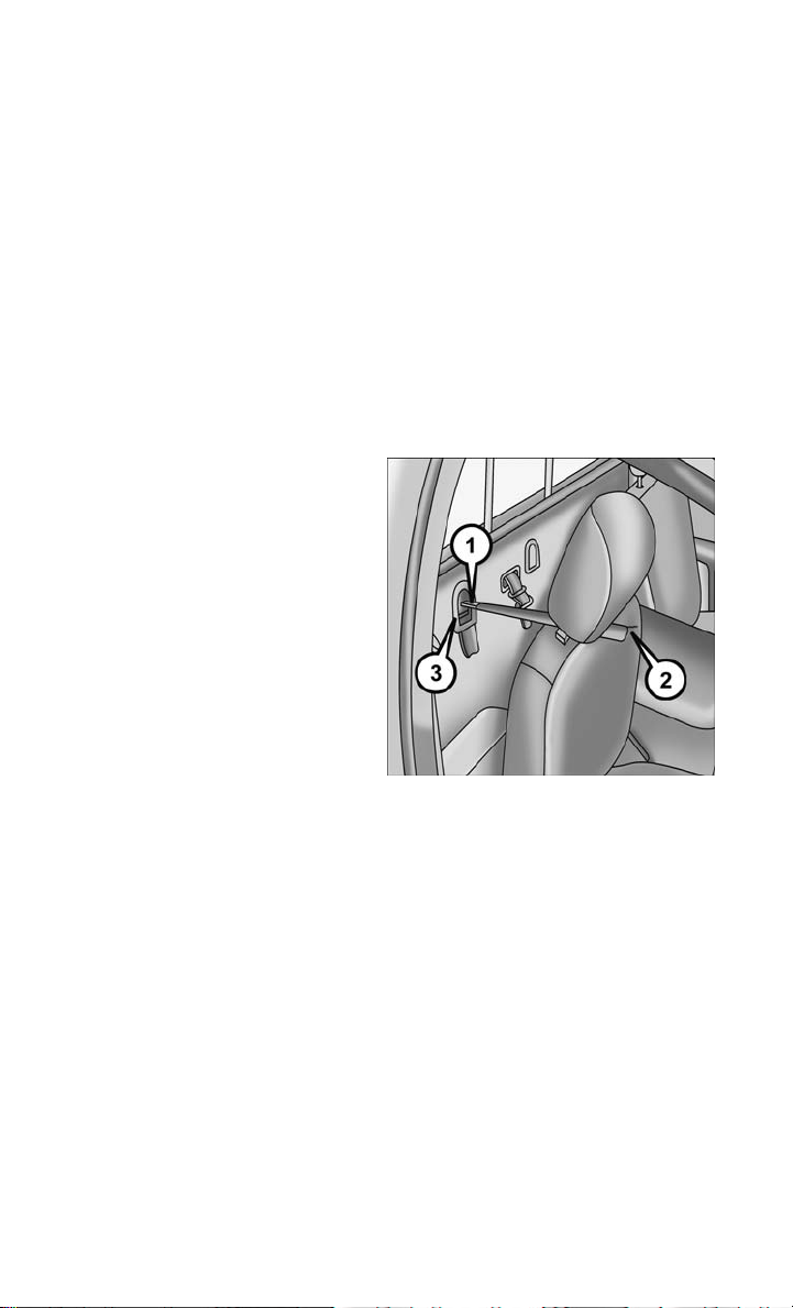
Crew Cab Trucks:
The top tether anchorages in this vehicle are tether strap loops located between the
rear glass and the back of the rear seat. There is a tether strap loop located behind
each seating position. Follow the steps below to attach the tether strap of the child
restraint.
Right or Left Outboard Seats:
1. Raise the head restraint and reach between the rear seat and rear glass to access
the tether strap loop.
Head Restraint In Raised Position Tether Strap Loop With Center Head
2. Place a child restraint on the seat and adjust the tether strap so that it will reach
over the seat back, under the head restraint, through the tether strap loop behind
the seat and over to the tether strap loop behind the center seat.
3. Pass the tether strap hook under the head restraint behind the child seat, through
the tether strap loop behind the seat and over to the center tether strap loop.
Restraint In Raised Position
Tether Strap Through Outboard Tether Strap
Loop
25

GETTING STARTED
4. Attach the hook to the center tether strap loop (see diagram). Tighten the tether
strap according to the child seat manufacturer’s instructions.
NOTE:
If there are child seats in both of the
outboard (left and right) seating positions, the tether strap hooks of both child
seats should be connected to the center
tether strap loop. This is the correct way
to tether two outboard child seats.
Tether Strap Through Outboard Tether Strap
Loop And Attached To Center Tether Strap
Center Seat:
1. Raise the head restraint and reach between the rear seat and rear glass to access
the tether strap loop.
2. Place a child restraint on the seat and
adjust the tether strap so that it will
reach over the seat back, under the
head restraint, through the tether
strap loop behind the seat and over to
the tether strap loop behind either the
right or left outboard seat.
Loop
26
Tether Strap Loop With Head Restraint In
Raised Position

GETTING STARTED
3. Pass the tether strap hook under the head restraint behind the child seat, through
the tether strap loop behind the seat and over to the right or left outboard tether
strap loop.
4. Attach the hook to the outboard tether
strap loop (see diagram). Tighten the
tether strap according to the child
seat manufacturer’s instructions.
Installing Three Child Restraints:
1. Place a child restraint on each outboard rear seat. Route the tether
straps following the directions for
right and left seating positions, above.
2. Attach both hooks to the center tether
strap loop, but do not tighten the
straps yet.
3. Place a child restraint on the center
rear seat. Route the tether strap following the directions for the center
seating position, above.
4. Attach the hook to the outboard tether
strap loop.
Tether Strap Through Center Tether Strap
Loop
Tether Strap Through Center Tether Strap
Loop And Attached To Outboard Tether Strap
Loop
Left Outboard And Center Seating Position
Shown
27

GETTING STARTED
5. Tighten the tether straps according to the child seat manufacturer’s instructions,
tightening the right and left tether straps before the center tether strap.
WARNING!
• In a collision, an unrestrained child, even a tiny baby, can become a projectile
inside the vehicle. The force required to hold even an infant on your lap could
become so great that you could not hold the child, no matter how strong you are.
The child and others could be severely injured or killed. Any child riding in your
vehicle should be in a proper restraint for the child's size.
• Never place a rear-facing child restraint in front of an air bag. A deploying
Passenger Advanced Front Air Bag can cause death or serious injury to a child
12 years or younger, including a child in a rear-facing child restraint.
• Only use a rear-facing child restraint in a vehicle with a rear seat.
• Improper installation of a child restraint to the LATCH anchorages can lead to
failure of an infant or child restraint. The child could be severely injured or
killed. Follow the manufacturer’s directions exactly when installing an infant or
child restraint.
• An incorrectly anchored tether strap could lead to increased head motion and
possible injury to the child. Use only the anchor positions directly behind the
child seat to secure a child restraint top tether strap.
• If your vehicle is equipped with a split rear seat, make sure the tether strap does
not slip into the opening between the seatbacks as you remove slack in the strap.
HEAD RESTRAINTS
Head restraints are designed to reduce the risk of injury by restricting head
movement in the event of a rear impact. Head restraints should be adjusted so that
the top of the head restraint is located above the top of your ear.
WARNING!
The head restraints for all occupants must be properly installed and adjusted prior
to operating the vehicle or occupying a seat. Head restraints should never be
adjusted while the vehicle is in motion. Driving a vehicle with the head restraints
improperly adjusted or removed could cause serious injury or death in the event of
a collision.
28
 Loading...