

RAM Chassis CAB 2018 Owner's Manual

2018
OWNER’S MANUAL
Chassis CAB

VEHICLES SOLD IN CANADA
With respect to any Vehicles Sold in Canada, the name
FCA US LLC shall be deemed to be deleted and the name
FCA Canada Inc. used in substitution therefore.
DRIVING AND ALCOHOL
Drunken driving is one of the most frequent causes of
accidents.
Your driving ability can be seriously impaired with blood
alcohol levels far below the legal minimum. If you are
drinking, don’t drive. Ride with a designated nondrinking driver, call a cab, a friend, or use public transportation.
WARNING!
Driving after drinking can lead to an accident.
Your perceptions are less sharp, your reflexes are
slower, and your judgment is impaired when you
have been drinking. Never drink and then drive.
This manual illustrates and describes the operation of
features and equipment that are either standard or optional on this vehicle. This manual may also include a
description of features and equipment that are no longer
available or were not ordered on this vehicle. Please
disregard any features and equipment described in this
manual that are not on this vehicle.
FCA US LLC reserves the right to make changes in design
and specifications, and/or make additions to or improvements to its products without imposing any obligation
upon itself to install them on products previously manufactured.
Copyright © 2017 FCA US LLC

SECTION PAGE
INTRODUCTION ...................................................................3
1
GRAPHICAL TABLE OF CONTENTS ......................................................9
2
GETTING TO KNOW YOUR VEHICLE ...................................................15
3
GETTING TO KNOW YOUR INSTRUMENT PANEL .........................................125
4
SAFETY ........................................................................159
5
TABLE OF CONTENTS
1
2
3
4
5
STARTINGANDOPERATING.........................................................235
6
INCASEOFEMERGENCY ...........................................................317
7
SERVICING AND MAINTENANCE .....................................................355
8
TECHNICAL SPECIFICATIONS ........................................................423
9
MULTIMEDIA ....................................................................437
10
CUSTOMER ASSISTANCE ............................................................503
11
INDEX..........................................................................509
12
6
7
8
9
10
11
12


INTRODUCTION
CONTENTS
䡵 INTRODUCTION .........................4
1
䡵 WARNINGS AND CAUTIONS ................7
䡵 HOW TO USE THIS MANUAL ...............5
▫ Essential Information ......................5
▫ Symbols ...............................6
䡵 VAN CONVERSIONS/CAMPERS ..............7
䡵 VEHICLE MODIFICATIONS/ALTERATIONS .....7

4 INTRODUCTION
INTRODUCTION
Dear Customer, congratulations on selecting your new
vehicle. Be assured that it represents precision workmanship, distinctive styling, and high quality.
This is a specialized utility vehicle. It can go places and
perform tasks that conventional passenger vehicles are not
intended. It handles and maneuvers differently from many
passenger vehicles both on-road and off-road, so take time
to become familiar with your vehicle. If equipped, the
two-wheel drive version of this vehicle was designed for
on-road use only. It is not intended for off-road driving or
use in other severe conditions suited for a four-wheel drive
vehicle. Before you start to drive this vehicle, read the
Owner’s Manual. Be sure you are familiar with all vehicle
controls, particularly those used for braking, steering,
transmission, and transfer case shifting. Learn how your
vehicle handles on different road surfaces. Your driving
skills will improve with experience. When driving off-road,
or working the vehicle, don’t overload the vehicle or expect
the vehicle to overcome the natural laws of physics.
Always observe federal, state, provincial and local laws
wherever you drive. As with other vehicles of this type,
failure to operate this vehicle correctly may result in loss of
control or a collision. Refer to the “Driving Tips” section for
further information.
This Owner’s Manual has been prepared with the assistance of service and engineering specialists to acquaint you
with the operation and maintenance of your vehicle. It is
supplemented by Warranty Information, and customer
oriented documents. In the attached Warranty Booklet you
will find a description of the services that FCA offers to its
customers, the Warranty Certificate and the details of the
terms and conditions for maintaining its validity. Please
take the time to read all of these publications carefully
before driving your vehicle for the first time. Following the
instructions, recommendations, tips, and important warnings in this manual will help assure safe and enjoyable
operation of your vehicle.
This Owner’s Manual describes all versions of this vehicle.
Options and equipment dedicated to specific markets or
versions are not expressly indicated in the text. Therefore,
you should only consider the information which is related
to the trim level, engine, and version that you have
purchased. Any content introduced throughout the Owner’s Information, that may or may not be applicable to your
vehicle, will be identified with the wording “If Equipped”.
All data contained in this publication are intended to help
you use your vehicle in the best possible way. FCA aims at
a constant improvement of the vehicles produced. For this
reason, it reserves the right to make changes to the model

described for technical and/or commercial reasons. For
further information, contact an authorized dealer.
If applicable, refer to the owners manual supplement for
related information.
NOTE: After reviewing the Owner’s Information, it should
be stored in the vehicle for convenient referencing, and
remain with the vehicle when sold.
When it comes to service, remember that your authorized
dealer knows your vehicle best, has factory-trained technicians and genuine MOPAR® parts, and cares about your
satisfaction.
INTRODUCTION 5
HOW TO USE THIS MANUAL
1
Essential Information
Consult the Table of Contents to determine which section
contains the information you desire.
Since the specification of your vehicle depends on the items
of equipment ordered, certain descriptions and illustrations may differ from your vehicle’s equipment.
The detailed index at the back of this Owner’s Manual
contains a complete listing of all subjects.

6 INTRODUCTION
Symbols
Consult the following table for a description of the symbols
that may be used on your vehicle or throughout this
Owner’s Manual:
WARNINGS AND CAUTIONS
This Owner’s Manual contains WARNINGS against oper-
ating procedures that could result in a collision, bodily
injury and/or death. It also contains CAUTIONS against
procedures that could result in damage to your vehicle. If
you do not read this entire Owner’s Manual, you may miss
important information. Observe all Warnings and Cautions.
VAN CONVERSIONS/CAMPERS
The New Vehicle Limited Warranty does not apply to body
modifications or special equipment installed by van
conversion/camper manufacturers/body builders. U.S.
residents refer to the Warranty Information book, Section
2.1.C. Canadian residents refer to the “What Is Not Covered” section of the Warranty Information book. Such
equipment includes video monitors, VCRs, heaters, stoves,
refrigerators, etc. For warranty coverage and service on
these items, contact the applicable manufacturer.
INTRODUCTION 7
Operating instructions for the special equipment installed
by the conversion/camper manufacturer should also be
supplied with your vehicle. If these instructions are missing, please contact your authorized dealer for assistance in
obtaining replacement documents from the applicable
manufacturer.
For information on the Body Builder’s Guide refer to
www.rambodybuilder.com. This website contains dimensional and technical specifications for your vehicle. It is
intended for Second Stage Manufacturer’s technical support. For service issues, contact your authorized dealer.
VEHICLE MODIFICATIONS/ALTERATIONS
WARNING!
Any modifications or alterations to this vehicle could
seriously affect its roadworthiness and safety and may
lead to a collision resulting in serious injury or death.
1


GRAPHICAL TABLE OF CONTENTS
CONTENTS
䡵 FRONT VIEW ...........................10
2
䡵 INSTRUMENT PANEL .....................12
䡵 REAR VIEW.............................11
䡵 INTERIOR ..............................13

10 GRAPHICAL TABLE OF CONTENTS
FRONT VIEW
Front View
1 — Exterior Mirrors 4 — Windshield
2 — Doors 5 — Headlights
3 — Wheels/Tires 6 — Hood/Engine Compartment
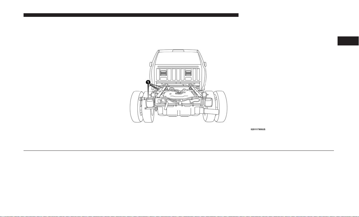
REAR VIEW
1 — Rear Lights
GRAPHICAL TABLE OF CONTENTS 11
2
Rear View

12 GRAPHICAL TABLE OF CONTENTS
INSTRUMENT PANEL
Instrument Panel
1 — Air Vents 4 — Instrument Cluster
2 — Multifunction Lever 5 — Radio
3 — Steering Wheel

INTERIOR
Interior
1 — Door Locks/Window Switches 4 — Switch Panel
2 — Seats 5 — Climate Controls
3 — Gear Selector
GRAPHICAL TABLE OF CONTENTS 13
2


GETTING TO KNOW YOUR VEHICLE
CONTENTS
䡵 KEYS .................................19
▫ Key Fobs .............................19
䡵 IGNITION SWITCH .......................25
▫ Wireless Ignition Node (WIN) — If Equipped....25
▫ Keyless Push Button Ignition — If Equipped ....28
▫ Key-In-Ignition Reminder .................28
䡵 REMOTE START — IF EQUIPPED .............29
▫ How To Use Remote Start..................29
▫ Remote Start Abort Message ...............29
▫ To Enter Remote Start Mode ................30
▫ To Exit Remote Start Mode Without Driving The
Vehicle ...............................30
▫ To Exit Remote Start Mode And Drive The
Vehicle ...............................30
▫ Remote Start Comfort Systems — If Equipped . . .30
▫ General Information .....................31
3
䡵 SENTRY KEY ...........................31
▫ Customer Key Programming ...............32
▫ Replacement Keys .......................32
▫ General Information .....................33
䡵 VEHICLE SECURITY ALARM ...............33
▫ To Arm The System ......................33
▫ To Disarm The System ....................34
▫ Rearming Of The System ..................34
▫ Security System Manual Override ............34
䡵 DOORS ...............................35
▫ Manual Door Locks ......................35
▫ Power Door Locks — If Equipped ...........36
▫ Keyless Enter-N-Go — Passive Entry .........36

16 GETTING TO KNOW YOUR VEHICLE
▫ Automatic Door Locks — If Equipped ........39
䡵 STEERING WHEEL .......................56
▫ Child-Protection Door Lock ................40
䡵 SEATS ................................41
▫ Manual Front Seat Adjustment ..............42
▫ Manual Rear Seat Adjustment ...............43
▫ Power Driver Seat Adjustment — If Equipped . . .44
▫ Power Passenger Seat Adjustment —
If Equipped ...........................46
▫ Driver Memory Seat — If Equipped ..........47
▫ Heated Seats — If Equipped ...............50
▫ Ventilated Seats — If Equipped ..............52
▫ Plastic Grocery Bag Retainers
(Regular Cab Models) ....................53
䡵 HEAD RESTRAINTS ......................53
▫ Front Head Restraint Adjustment ............53
▫ Rear Head Restraint Adjustment .............54
▫ Front Head Restraint Removal ..............55
▫ Rear Head Restraint Removal ...............55
▫ Tilt Steering Column .....................56
▫ Heated Steering Wheel — If Equipped.........57
䡵 DRIVER ADJUSTABLE PEDALS —
IF EQUIPPED ...........................57
䡵 MIRRORS ..............................59
▫ Inside Day/Night Mirror — If Equipped ......59
▫ Automatic Dimming Mirror — If Equipped .....59
▫ Automatic Dimming Mirror With Rear View
Camera Display — If Equipped .............60
▫ Outside Mirrors ........................61
▫ Driver’s Outside Automatic Dimming Mirror — If
Equipped .............................61
▫ Power Mirrors — If Equipped ..............62
▫ Power Folding Outside Mirrors For Standard And
Trailer Tow — If Equipped .................63
▫ Trailer Towing Mirrors — If Equipped ........65
▫ Heated Mirrors — If Equipped .............65

▫ Tilt Side Mirrors In Reverse — If Equipped .....66
GETTING TO KNOW YOUR VEHICLE 17
▫ Turn Signals ...........................73
▫ Illuminated Vanity Mirror — If Equipped ......66
䡵 EXTERIOR LIGHTS .......................67
▫ Headlight Switch .......................67
▫ Headlights ............................68
▫ Daytime Running Lights (DRL) — If Equipped . .69
▫ Multifunction Lever .....................69
▫ High/Low Beam Switch ..................69
▫ Automatic High Beam Headlamp Control — If
Equipped .............................69
▫ Flash-To-Pass ..........................70
▫ Automatic Headlights — If Equipped .........70
▫ Parking Lights And Panel Lights .............71
▫ Headlights On With Wipers (Available With
Automatic Headlights Only) ................71
▫ Headlight Delay ........................72
▫ Lights-On Reminder......................72
▫ Fog Lights — If Equipped .................72
▫ Lane Change Assist — If Equipped ..........73
▫ Cargo Light ...........................73
▫ Battery Saver ...........................74
䡵 INTERIOR LIGHTS .......................74
▫ Courtesy Lights .........................74
▫ Illuminated Approach ....................76
䡵 WINDSHIELD WIPERS AND WASHERS ........77
▫ Windshield Wipers ......................77
▫ Rain Sensing Wipers — If Equipped ..........78
䡵 CLIMATE CONTROLS .....................80
▫ Manual Climate Controls Without Touchscreen . .80
▫ Manual Climate Controls With A Touchscreen . . .84
▫ Automatic Climate Controls With A
Touchscreen ...........................85
▫ Climate Control Functions .................91
▫ Automatic Temperature Control (ATC) — If
Equipped .............................92
3

18 GETTING TO KNOW YOUR VEHICLE
▫ Operating Tips .........................93
▫ Using HomeLink .......................105
䡵 WINDOWS .............................96
▫ Power Windows — If Equipped .............96
▫ Wind Buffeting .........................98
䡵 HOOD ................................98
▫ To Open The Hood ......................98
▫ To Close The Hood ......................99
䡵 GARAGE DOOR OPENER — IF EQUIPPED .....99
▫ Before You Begin Programming HomeLink . . . .100
▫ Programming A Rolling Code ..............101
▫ Programming A Non-Rolling Code ..........103
▫ Canadian/Gate Operator Programming .......104
▫ Security..............................105
▫ Troubleshooting Tips ....................106
▫ General Information .....................107
䡵 INTERNAL EQUIPMENT ..................107
▫ Storage ..............................107
▫ Cupholders ...........................118
▫ Electrical Power Outlets ..................119
▫ Cigar Lighter And Ash Receiver —
If Equipped ..........................123
▫ Power Inverter — If Equipped .............123
▫ Auxiliary Switches — If Equipped ..........124

KEYS
Key Fobs
Your vehicle uses either a wireless ignition node system or
keyless ignition system. The ignition system consists of a
key fob with a Remote Keyless Entry (RKE) and an ignition
switch. The keyless ignition system consists of a key fob
and Keyless Enter-N-Go button.
NOTE: The key fob may not be found if it is located next to
a mobile phone, laptop or other electronic device; these
devices may block the key fob’s wireless signal.
The key fob operates the ignition switch. Insert the square
end of the key fob into the ignition switch located on the
instrument panel and rotate to the desired position. It also
contains the key fob and an emergency key, which stores in
the rear of the key fob.
The emergency key allows for entry into the vehicle should
the battery in the vehicle or the key fob go dead. You can
keep the emergency key with you when valet parking.
To remove the emergency key, slide the mechanical latch at
the top of the key fob sideways with your thumb and then
pull the key out with your other hand.
GETTING TO KNOW YOUR VEHICLE 19
NOTE: When using the emergency key to gain access to
your vehicle, be aware that the security alarm may be
triggered. Insert the key into the ignition and place the
ignition in the ON/RUN mode to disarm the security
system.
Emergency Key Removal
3

20 GETTING TO KNOW YOUR VEHICLE
This Keyless Push Button Ignition key fob allows the driver
to operate the ignition switch with the push of a button, as
long as the key fob is in the passenger compartment. The
Keyless Push Button Ignition has four operating positions,
three of which are labeled and will illuminate when in
position. The three positions are OFF, ACC, and ON/RUN.
The fourth position is START, during start RUN will
illuminate. It also contains the key fob and an emergency
key, which stores in the rear of the key fob.
The emergency key allows for entry into the vehicle should
the battery in the vehicle or the key fob go dead. You can
keep the emergency key with you when valet parking.
To remove the emergency key, slide the mechanical latch
on the backside of the key fob sideways with your thumb
and then pull the key out with your other hand.
NOTE: When using the emergency key to gain access to
your vehicle, be aware that the security alarm may be
triggered. Put the nose side (side opposite of the emergency key) of the key fob against the ENGINE START/
STOP button and push to disarm the security system.
Key Fob Emergency Key
NOTE: You can insert the double-sided emergency key
into the door lock cylinder with either side up.
The Remote Keyless Entry system allows you to lock or
unlock all doors, and the tailgate as well as activate the
Panic Alarm from distances up to approximately 66 ft (20
m) using a key fob with integrated key. The key fob does
not need to be pointed at the vehicle to activate the system.
Push and release the lock button on the key fob to lock all
doors, and the tailgate. The turn signal lights will flash and
the horn will chirp to acknowledge the signal.
NOTE: Inserting the key fob with integrated key into the
ignition switch disables the system from responding to any
button pushes from that key fob. Driving at speeds 5 mph
(8 km/h) and above disables the system from responding
to all key fob buttons for all key fobs.
WIN Key Fob With Integrated Key
GETTING TO KNOW YOUR VEHICLE 21
3
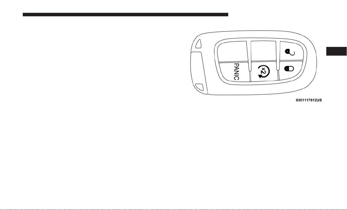
Passive Entry Key Fob
To Unlock The Doors And Tailgate
Push and release the unlock button on the key fob once to
unlock the driver’s door. Push the unlock button twice
within five seconds to unlock all doors, and the tailgate.
The turn signal lights will flash to acknowledge the unlock
signal. The illuminated entry system will also turn on.
NOTE: The instrument cluster display or Uconnect Settings are setup for driver door first, otherwise this will
unlock all doors.

22 GETTING TO KNOW YOUR VEHICLE
To Lock The Doors And Tailgate
Push and release the lock button on the key fob to lock all
doors, and the tailgate. The turn signal lights will flash and
the horn will chirp to acknowledge the signal.
Sound Horn With Remote Key Lock
This feature will cause the horn to chirp when the doors are
locked with the key fob. This feature can be turned on or
turned off. To change the current setting, proceed as
follows:
• For vehicles not equipped with a touchscreen radio,
refer to “Instrument Cluster Display” in “Getting To
Know Your Instrument Panel” for further information.
• For vehicles equipped with a touchscreen radio, refer to
“Uconnect Settings” in “Multimedia” for further information.
NOTE: Pushing the lock button on the key fob while you
are in the vehicle will activate the vehicle security alarm
system. Opening a door with the vehicle security alarm
system activated will cause the alarm to sound. Push the
unlock button to deactivate the vehicle security alarm
system.
Using The Panic Alarm
To turn the Panic Alarm feature on or off, push the Panic
button on the key fob. When the Panic Alarm is activated,
the turn signals will flash, the horn will pulse on and off,
and the interior lights will turn on.
The Panic Alarm will stay on for three minutes unless you
turn it off by either pushing the Panic button a second time
or drive the vehicle at a speed of 15 mph (24 km/h) or
greater.
NOTE:
• The interior lights will turn off if you place the ignition
in the ACC or ON/RUN position while the Panic Alarm
is activated. However, the exterior lights and horn will
remain on.
• You may need to be less than 35 ft (11 m) from the
vehicle when using the key fob to turn off the Panic
Alarm due to the radio frequency noises emitted by the
system.
Replacing The Battery In The Key Fob With Remote Control
The recommended replacement battery is one CR2032
battery.

NOTE:
• Perchlorate Material — special handling may apply. See
www.dtsc.ca.gov/hazardouswaste/perchlorate
• Do not touch the battery terminals that are on the back
housing or the printed circuit board.
1. Remove the emergency key by sliding the mechanical
latch on the back of the key fob sideways with your
thumb and then pull the key out with your other hand.
Emergency WIN Key Removal
GETTING TO KNOW YOUR VEHICLE 23
3
Emergency Key Removal
24 GETTING TO KNOW YOUR VEHICLE
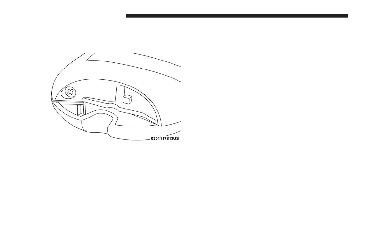
2. Separating key fob halves requires screw removal – if
equipped, and gently prying the two halves of the key
fob apart. Make sure not to damage the seal during
removal.
Remove Screw From Key Fob Case
Separating WIN Key Fob Case

GETTING TO KNOW YOUR VEHICLE 25
Programming Additional Key Fobs
Programming the key fob may be performed by an authorized dealer.
Separating Key Fob Case
3. Remove the battery by turning the back cover over
(battery facing downward) and tapping it lightly on a
solid surface such as a table or similar, then replace the
battery. When replacing the battery, match the + sign on
the battery to the + sign on the inside of the battery clip,
located on the back cover. Avoid touching the new
battery with your fingers. Skin oils may cause battery
deterioration. If you touch a battery, clean it with
rubbing alcohol.
4. To assemble the key fob case, snap the two halves
together, reposition and secure the screw as shown in
step #2 for removal.
General Information
The following regulatory statement applies to all radio
frequency (RF) devices equipped in this vehicle:
This device complies with Part 15 of the FCC Rules and
with Industry Canada license-exempt RSS standard(s).
Operation is subject to the following two conditions:
1. This device may not cause harmful interference, and
2. This device must accept any interference received, including interference that may cause undesired operation.
NOTE: Changes or modifications not expressly approved
by the party responsible for compliance could void the
user’s authority to operate the equipment.
IGNITION SWITCH
Wireless Ignition Node (WIN) — If Equipped
The Wireless Ignition Node (WIN) operates similar to an
ignition switch. It has four operating positions, three with
3

26 GETTING TO KNOW YOUR VEHICLE
detents and one that is spring-loaded. The detent positions
are OFF, ACC, and ON/RUN. The START position is a
spring-loaded momentary contact position. When released
from the START position, the switch automatically returns
to the ON/RUN position.
Wireless Ignition Switch
1 — OFF
2 — ACC (Accessory)
3 — ON/RUN
4 — START
Removing Key Fob From The (WIN) Ignition
Place the gear selector in PARK (if equipped with an
automatic transmission). Turn the key fob to the OFF
position and then remove the key fob.
NOTE:
• The power window switches, radio, power sunroof (if
equipped), and power outlets will remain active for up
to 10 minutes after the ignition switch is turned to the
OFF position. Opening either front door will cancel this
feature. Refer to “Uconnect Settings” in “Multimedia”
for further information.
• For vehicles not equipped with a touchscreen radio,
refer to “Instrument Cluster Display⬙ in “Getting To
Know Your Instrument Panel” for further information.
• For vehicles equipped with a touchscreen radio, refer to
“Uconnect Settings” in “Multimedia” for further information.
GETTING TO KNOW YOUR VEHICLE 27
WARNING!
• Before exiting a vehicle, always shift the automatic
transmission into PARK or the manual transmission
into REVERSE, apply the parking brake, turn the
vehicle OFF, remove the key fobs from the vehicle,
and lock all doors. If equipped with Keyless EnterN-Go, always make sure the keyless ignition node is
in the OFF mode, remove the key fob from the
vehicle and lock the vehicle.
Never leave children alone in a vehicle, or with access
•
to an unlocked vehicle. Leaving children in a vehicle
unattended is dangerous for a number of reasons. A
child or others could be seriously or fatally injured.
Children should be warned not to touch the parking
brake, brake pedal or the gear selector.
• Allowing children to be in a vehicle unattended is
dangerous for a number of reasons. A child or others
could be seriously or fatally injured. Children
should be warned not to touch the parking brake,
brake pedal or gear selector.
(Continued)
WARNING! (Continued)
• Do not leave the key fob in or near the vehicle, or in
a location accessible to children, and do not leave the
ignition of a vehicle equipped with Keyless EnterN-Go in the ACC or ON/RUN mode. A child could
operate power windows, other controls, or move the
vehicle.
• Do not leave children or animals inside parked
vehicles in hot weather. Interior heat build-up may
cause serious injury or death.
CAUTION!
• If your vehicle battery becomes low or dead, your
key fobs will become locked in the ignition.
• Do not attempt to remove the key fobs while in this
condition, damage could occur to the key fobs or
ignition module. Only remove the emergency key for
locking and unlocking the doors.
• Leave the key fob in the ignition and either:
• Jump Start the vehicle.
• Charge the battery.
3

28 GETTING TO KNOW YOUR VEHICLE
CAUTION!
An unlocked vehicle is an invitation. Always remove
the key from the ignition and lock all doors when
leaving the vehicle unattended.
Keyless Push Button Ignition — If Equipped
This feature allows the driver to operate the ignition switch
with the push of a button as long as the Remote Keyless
Entry key fob is in the passenger compartment.
The Keyless Push Button Ignition has four operating
positions; three of which are labeled and will illuminate
when in position. The three positions are OFF, ACC, and
ON/RUN. The fourth position is START, during start RUN
will illuminate.
NOTE: In case the ignition switch does not change with
the push of a button, the key fob may have a low or dead
battery. In this situation, a back up method can be used to
operate the ignition switch. Put the nose side (side opposite
of the emergency key) of the key fob against the ENGINE
START/STOP button, with your foot applied on the brake
pedal, and push to operate the ignition switch.
Keyless Push Button Ignition
1—OFF
2 — ACC (Accessory)
3 — ON/RUN
Key-In-Ignition Reminder
Opening the driver’s door when the key fob is in the
ignition and the ignition switch position is OFF or ACC, a
chime will sound to remind you to remove the key fob.
 Loading...