

OPERATION MANUAL
NOTICE DEMPLOI
BEDIENUNGSANLEITUNG
J42646-054
QXPCBDoc
1/03
© 2003 by C.E. Studio-2 s.l. - Spain (EEC)
http://www.ramaudio.com
e-mail: support@ramaudio.com
Professional Power Amplifiers
CB Series
1402 / 1902 / 2602 / 3902

WARNING:
The exclamation point inside an
equilateral triangle indicates the existence of internal components whose substitution may affect safety.
The lightning and arrowhead symbol
warns about the presence of uninsulated dangerous voltage.
To avoid fire or electrocution risk do not
expose the unit to rain or moisture.
To avoid electric shock, do not open the
unit. No user serviciable parts inside. In
the case of disfunction, have the unit
checked by qualified agents.
Class I device.
SAFETY
PRECAUTIONS AVERTISSEMENTS
SICHERHEITSHINWEISE
CAUTION
RISK OF ELECTRIC SHOCK
DO NOT OPEN
ACHTUNG!:
Das Ausrufezeichen innerhalb eines
Dreiecks weist auf den Enthalt interner
Bauteile hin, dessen Austausch
sicherheitsbedingt ist.
Das Blitzzeichen zeigt die Gegenwart
unisolierter gefährlicher Spannungen
an.
Um Brand oder elektrische Schläge zu
vermeiden, setzen Sie diese Einheit
keiner starken Luftfeuchtigkeit oder
Regen aus.
Damit elektrisch Schläge vermieden
werden, öffnen Sie diese Einheit nich.
Bei Bedarf von Reparaturen, wenden
Sie sich an qualifiziertes Personal.
Es handelt sich um ein Gerät der
Klasse I.
1
VORSICHT
GEFAHR EINES
ELEKTRISCHEN SCHLAGES.
NICHT ÖFFNEN!
RÈGLES DE SÉCURITÉ:
Le trinagle ponctué du point d’exclamation central indique l’existence de composants internes affectant la sécurité de
personnes non agrées par nos S.A.V..
Le symbole éclair indique la présence
de points électriques internes non
isolés.
Pour écarter tout risque d’incendie ou
d’électrocution, ne pas exposer l’appareil à la pluie ni à l’humidité.
Afin d’éviter tout risque, ne pas ouvrir
l’appareil. Ne confier l’entretien de l’appareil qu’à du personnel technique qualifié et agréé.
Appareil de Classe I.
ATTENTION
RISQUE DE CHOC ÉLECTRIQUE
NE PAS OUVRIR

0 Safety Precautions
1 General Information
1.1 Introduction
1.2 Main Characteristics
2 Controls: Where and What?
2.1 Front Panel
2.2 Rear Panel
3 Installation and Operation
3.1 Connections
3.1.1 Dual Mode (Stereo)
3.1.2 Parallel Mode
3.1.3 Bridge Mode (Mono)
3.2 Troubleshooting
4 Technical Specifications
4.1 Protection Systems
4.2 Data
4.3 Electrical Schematic
©2003 by C.E. Studio-2 s.l.
Pol.Ind. La Lloma
C/Sierra Perenxisa nº20
46960 Aldaya - Valencia - SPAIN
Phone: +34 96 127 30 54
Fax: +34 96 127 30 56
http://www.ramaudio.com
e-mail: support@ramaudio.com
ram@ramaudio.com
RAM Audio
®
, CSP
™
, CRO™and ICL
™
are registered trademarks of
C.E. Studio-2 s.l.. All other names are
trademarks of their respective companies.
0 Sicherheitsanweisungen
1 Allgemeine Anweisungen
1.1 Einleitung
1.2 Allgemeine Eigenschaften
2 Lokalisierung der Funktionen
2.1 Frontplatte
2.2 Rückseite
3 Anschluss- und Inbetriebnahme
3.1 Anschlüsse
3.1.1 Zweikanalmodus (Stereo)
3.1.2 Parallelmodus
3.1.3 Einkanalmodus (Bridge)
3.2 Problemlösung
4 Technische Spezifikationen
4.1 SchutzschaltungenSystem
4.2 Technische Daten
4.3 Elektrische Diagramme
INHALTSVERZEICHNIS
INDEX
0 Avertissements
1 Informations Générales
1.1 Introduction
1.2 Caractéristiques générales
2 Emplacement des commandes et
leurs fonctions
2.1 Panneau avant
2.2 Panneau arrière
3 Installation et mise en route
3.1 Branchements
3.1.1 Fonctionnement en mode
stéréo
3.1.2 Fonctionnement en mode
paralléle
3.1.3 Fonctionnement en mode
mono (Bridge).
3.2 Dysfonctionnements éventuels
et dépannage.
4 Spécifications
4.1 Systémes de Protection
4.2 Données téchniques
4.3 Schémas
TABLE DES
MATIÈRES
2

The RAM®CB Series Power Amps
have been developped to meet the highest goals in the field of professional
power amplification. Their power, distortion and dynamics figures place them
as reference in the industry.
The CB Series incorporate unique
Absolute Protection Systems as the
CRO
™
, an immediate load disconnection system with an exclusive design
that excludes current in the output circuit relay, or the ICL
™
Clip-Limiter,
CSP
™
, ...
• Instantaneous High Flow Power
Supply.
• High Power Toroidal Transformer.
• Oversized Motorola
®
Output transis-
tors in the power modules.
• High Damping Factor.
• Unique Protection Systems: ICL
™
,
CSP
™
, CRO™ ...
• Dual, Bridge or Parallel operation
switch on rear panel.
• 2 U Rugged Steel Chassis.
• Twin Neutrik
®
XLR Connectors.
• Slow Start System with circuit relay
based speaker protection.
• Back to front twin cooling fans.
• Electronic continuously variable fan
speed control.
• Usable voltage 170-245V (230V nomi-
nal) or 90-128V (120V nominal).
• 2 ohms continuous operation.
1.2 Main Characteristics
1.1 Introduction
Die RAM® - Endstufen der CB-serie sind
dazu entwickelt worden, um den höchsten Anforderungen im professionellen
Audiobereich entgegenzukommen. Ihre
Eigenschaften bezüglich der Leistung,
Verzerrung und Dynamik machen au
der DQL-serie ein Referenzprodukt.
Die DQL-serie enthält einzigartige
Schutzschaltungen, wie z.B. ein anti-clip
system (ICL
®
) oder das automatische
stromlose Abkopplungssytem zum
Schutz der Lautsprecher am
Ausgangsrelais (CRO
®
).
• Trafoeinheit mit sofortigem
Hochstrom.
• Hochleistungs-Toroidaltrafo.
• Leistungsmodule mit überdimensio-
nierten Motorola
®
-Transistoren.
• Hoher Dämpfungsfaktor.
• Einzigartige Schutzschaltungen (ICL
®
,
CSP
®
, CRO®, u.a.)
• Dual, Bridge and Parallel mode shal-
ter auf der Rückseite.
• Standardhöhe von zwei
Rackeinheiten.
• Doppelte Neutrik
®
XLR - Stecker.
• Gestufte Einschalttechnik mit
Relaisschutz für die Lautsprecher
(Softstart)
• Lüfter mit stufenlos geregelter
Geschwindigkeit. Luftaustritt vorne.
• Elektronische Kontrolle der Lüfter.
• Voltage von 170-245V (230V nominal)
oder 90-128V (120V nominal).
• 2 ohms Anwendung.
1.2 Allgemeine Eigenschaften
1.1 Einleitung
General Information
Les amplificateurs de puissance RAM
®
CB Series satisfont aux plus hautes exigences des professionnels de la sonorisation. Leurs caractéristiques de puissance, distorsion et réponse transitoire
font des amplificateurs de puissance
DQL, de véritables outils de référence
faisant rimer qualité de fabrication avec
pureté du son.
Les séries DQL sont dotées de plusieurs systèmes de protection électroniques brevetés, à l’instar du système
anti-clipping aservi (ICL
®
) sans influence sur l’écoute, du système de connexion / déconnexion sécurisé pour les
HP, par absence de courant aux relais
(CRO
®
), ou de la tenue des courtcircuits permanents à pleine charge par
temporisation (CSP
®
).
• Grande capacité en courant instan-
tané.
• Transformateur torique surdimen-
sionné.
• Modules de puissance munis de tran-
sistors Motorola
®
amplement dimen-
sionnés.
• Très haut facteur d’amortissement.
• Protections de l’electronique et des
HP brevetées: ICL
®
, CSP®, CRO®...
• Conmutateur de mise en mode
Bridge, Dual ou Parallèle sur le panneau arrière.
• Châssis extrêmement robuste, en
fonte d’acier.
• Connecteurs d’entrée type XLR
Neutrik
®
doublés (entrée-sortie).
• Temporisation à la mise sous tension.
• Refroidissement assuré par ventilation
forcée de l’arrière vers l’avant.
• Vitesse des ventilateurs asservie en
fonction de la température interne.
• Voltage de fontionement 170-245V
(230V nominal) ou 90-128V (120V
nominal).
• Fontionnement à 2 ohms continu.
1.2 Caractéristiques Générales
1.1 Introduction
Informations
Générales
Allgemeine
Anweisungen
3
Lokalisierung der
Funktionen
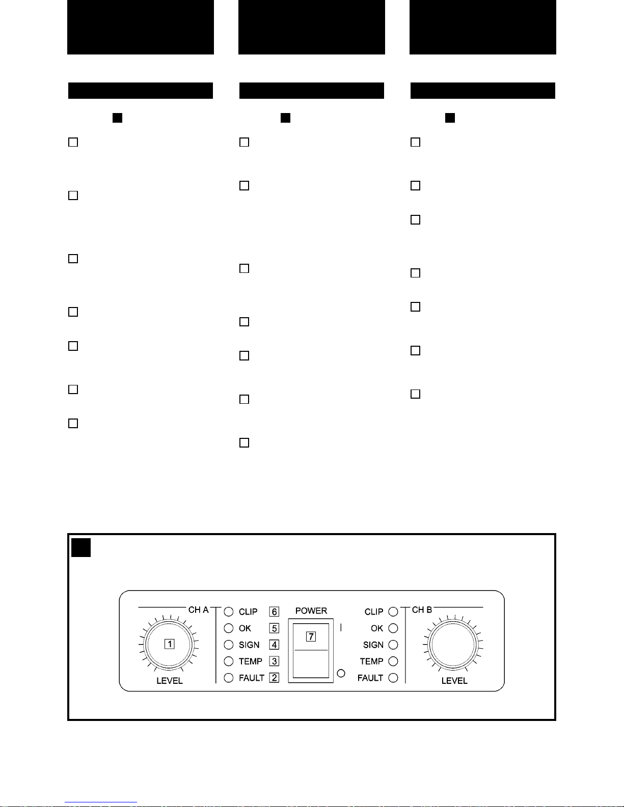
See Figure
Signal attenuation level control
knobs: Permit independent control
of each channel’s attenuation (41
steps).
FAULT: This LED shows the circuit
relay on the output has open obeying one or several protections’
orders from the amplifier: short circuit, low impedance, DC, start,...
TEMP: This LED shows temperature protection is active. Fault LED will
activate simultaneously indicating
loudspeaker disconnection.
SIGNAL: This LED indicates presence of signal at the inputs.
OK: LED indicating correct unit’s
function. Not lit only when ICL in
operation.
CLIP: LED indicating Intelligent Clip
Limiter in operation (see page 10).
Main Power Switch: Connects the
amplifier’s current feed.
7
6
5
4
3
2
1
1
2.1 Front Panel
Siehe Fig.
Lautstärkeregler: diese ermögli-
chen, die Signalstärke am Ausgang
in 41 Stufen zu regeln.
FAULT: Diese LED-Anzeige leuchtet
auf wenn das Schutzrelais durch
irgendeine der Shutzschaltungen
ausgelöst worden ist (Kurzschluss,
niedrige Impedanz, Anwesenheit
von Gleichstrom, beim
Einschalten...)
TEMP: LED-Anzeige leuchtet wenn
eine der Überwärmungsfunktionen
eintritt. Gleichzeitig schaltet sich
auch die Anzeige “FAULT” ein.
SIGNAL: Wachanzeige des einkommenden Signals.
OK: Anzeige für die korrekte
Funktion dieser Einheit. Wird nur im
Fall von “clipping” gelöscht.
CLIP: Die LED zeigt den Betrieb
des ICL (Intelligent Clip Limiters),
siehe Seite 10
Beleuchteter Hauptstromschalter:
Dieser Schalter schaltet die
Stromzuführung der Endstufe ein
und aus.
7
6
5
4
3
2
1
1
2.1 Frontplatte
Controls:
Where and What?
Voir Fig.
Atténuateurs de signal d’entrée
crantés: réglage du niveau d’entrée
indépendant sur chaque canal.
FAULT: signalisation par LED de la
coupure du signal de sortie.
TEMP: signalisation par LED de
temperature excessive. La LED de
signalisation FAULT s’activera
simultanément.
SIGNAL: indique la présence de
signaux d’entrée.
OK: signalisation d’un fonctionnement correct. Cette LED s´éteint en
cas de clipping.
CLIP: signalisation par LED de la
mise en fonctionnement du Limiteur
Intelligent d'écretage (voir page 10).
Power: Interrupteur de mise sous
tension.
7
6
5
4
3
2
1
1
2.1 Panneau Avant
Commandes et
Fonctions
4
1
Front Panel

See Figure
Signal Input: Twin female Neutrik
®
XLR Connectors for the amplifier’s
signal input.
Signal Link: Twin male Neutrik
®
XLR Connectors for daisy chaining
input signal to other amplifiers
(parallel connected to female input
connectors).
Ground Link: This switch permits
connection/disconnection of the
amp’s internal ground to general
earth.
Mains Cable: Mains and earth main
feed (220V-240V AC / 110V-120V
AC).
Speaker connectors: Neutrik
®
Speakon to connect the speakers.
Dual / Parallel / Bridge Operation
Selection Switch.
6
5
4
3
2
1
2
2.2 Rear Panel
Siehe Fig.
Eingangssignal: Neutrik
®
-XLR
Buchsen.
LINK: Paralele XLR-Ausgänge zur
Zusammenschaltung mehrerer
Endstufen.
GROUND LINK: Ermöglicht den
Anschluss der Erdung an die Masse
der internen Schaltung.
Stromkabel: 220V-240 V / 110V120V AC Wechselstrom mit
Erdanschluss.
Dautsprecheranschluss: Neutrik
Speakon Stecker zum Anschluss
externer Lautsprecher. Der
Anschluss erfolgt über Kabel mit
entfernter Isolierung.
Dual / Parallel / Bridge: Dieser
Schalter wechselt von
Zweikanaloperation zu Bridge oder
Parallel Modus.
6
5
4
3
2
1
2
2.2 Rückseite
Lokalisierung der
Funktionen
5
Controls:
Where and What?
Voir Fig.
Connecteurs Neutrik
®
XLR (feme-
lle) d’entrée des signaux de modu-
lation.
Connecteurs Neutrik®XLR (mâle),
sortie des signaux d’entrée pour la
mise en parallèle d’autres amplis.
GND Link: Commutateur de mise à
la terre de la masse générale.
Câble d’alimentation générale
(220V-240V AC / 110V-120V AC).
Bornes de sortie (Speakon) pour
le branchement des HP.
Dual / Parallel / Bridge: Sélecteur
de mode pont (Bridge), parallele ou
stéréo.
6
5
4
3
2
1
2
2.2 Panneau Arrière
Commandes et
Fonctions
2
Rear Panel

The Power switch must always be on
the “Off” position before plugging the
amp to a properly earthed mains socket (220-240V AC / 110V-120V AC).
The input signal fed to the amplifier can
be either balanced or un-balanced. The
drawing below describes both ways to
wire an XLR connector for the purpose.
Balanced Signal: Connect pin 1 to
Ground, pin 2 to Signal + (hot) and pin
3 to Signal - (cold).
Unbalanced Signal: Connect Pin 1 to
Ground, pin 2 to Signal and pin 3 to
Ground.
Important!: If a connection is done with
a un-balanced line and pin 3 on the
XLR is not connected to ground, a 6 dB
loss occurs in the line and only a quarter of the amplifier power is produced.
The amplifier provides, for each channel, a female XLR Connector (Signal
Input) parallelled to a male XLR to daisy
chain several amplifiers with the same
signal line (LINK).
3.1 Connections
Bevor Sie diese Einheit an eine
SHUKO-Steckdose anschliessen, schalten Sie den Hautstromschalter Aus.
Das Eingangssignal kann entweder
symmetrisch oder unsymmetrisch sein.
Der Anschluss wird gemacht wie folgt.
Symmetrisches Signal: Die Belegung
der XLR Pins ist folgende: 1-Masse, 2Positives Signal (hot), 3-Negatives
Signal (cold).
Asymetrisches Signal: Die Belegung
der XLR Pins ist folgende: 1-Masse, 2Signal, 3-Masse.
ACHTUNG! Wenn Sie ein
Asymetrisches Signal anschliessen und
Pin 3 nicht an Masse anschliessen,
erzeugt sich ein Verlust von 6dB (1/4
der Leistung der Endstufe) am usgangssignal.
Die Endstufe rechnet mit einer paralelen
XLR-Buchse, die zum Anschluss an
weitere Endstufen dient.
3.1 Anschluss
Installation and
Operation
Veillez à ce que l’interrupteur de mise
en service soit en position “Off” avant
de brancher l’appareil sur une prise
secteur avec mise à la terre (220V240V AC / 110V-120V AC)
L’appareil peut fonctionner avec des
signaux symétriques ou assymétriques.
La figure ci-dessous indique le câblage
des connecteurs XLR pour les deux
cas.
Câblage Symétrique: souder la broche
1 à la masse, la broche 2 au point
chaud (+), et la broche 3 au point froid
(-).
Câblage Assymétrique: souder les
broches 1 et 3 à la masse, et la broche
2 au signal.
Important: Si on effectue le branchement d’un signal asymetrique sur le
connecteur XLR sans relier la broche 3
à la masse, une perte de 6dB sera
constatée , ce qui se traduira par une
perte du 75% de la puissance de sortie.
L’amplificateur est muni des connecteurs XLR mâle pour la mise en
parallèle de plusieurs amplificateurs
avec les mêmes signaux d’entrée.
3.1 Branchement
Installation et
mise en service
Anschluss und
Inbetriebnahme
Balanced Wiring
1- Ground
2- Signal +
3- Signal -
Unbalanced Wiring
1- Ground
2- Signal
3- Ground
6

Installation and
Operation
Installation et
mise en service
The amplifier can operate on three different configurations: DUAL, BRIDGE or
PARALLEL. The connections for the
three modes are different.
See Figure
- Switch “Off” the amp.
- Set the Mode Switch on the rear panel
to “DUAL”.
- Connect the signal lines to the female
XLR connectors on both channels.
- Connect the speakers’ lines to the
corresponding binding posts or
Speakon on the amp respecting the
polarity.
- Switch “On” the amp.
- Use the level control knob on the front
panel to adjust each channel independently.
- Each signalling LED group will show
its corresponding channel status.
See Figure
- Operate as Dual Channel Mode with a
single signal input on Channel “A”.
See Figure
- Switch “Off” the amp.
- Set the Mode Switch on the rear panel
to “SINGLE” (Bridge).
- Connect a signal line to input female
XLR Channel “A”
.
- Connect the speaker line at the two
positive (Red) binding posts. Channel
“A” post becoming the positive in this
configuration. Alternatively use the
Channel A Speakon wired to +1 and
+2. In this way pin +1 is positive.
- Switch “On” the amp.
- Use both control knobs at the same
level to adjust the single amp’s output.
- Both signalling LED groups will show
the single channel status.
5
3.1.3 Single Channel Mode (Bridge)
4
3.1.2 Parallel Channel Mode
3
3.1.1 Dual Channel Mode (Stereo)
L’amplificateur peut fonctionner en
mode stéréo, parallèle ou ponté
(Bridge). Le branchement est différent
pour ces trois modes.
Voir Fig.
- Commuter l’interrupteur de mise en
service sur position “Off”.
- Sélectionner le mode Stéréo sur le
panneau arrière de l’appareil.
- Bancher les signaux d’entrée aux
fiches XLR femelles des deux canaux.
- Brancher les haut-parleurs sur les bornes TP-6 en respectant les polarités.
- Commuter l’interrupteur de mise en
service sur position “On”.
- Utiliser les atténuateurs d’entrée en
face-avant pour régler le niveau de
sortie de chaque canal.
- Les indicateurs LED afficheront le
stade de chaque canal.
Voir Fig.
- Selectionner le mode Parallèle sur le
Panneau arrière de l'appareil. Utiliser
l'ampli comme en mode Dual mais
avec une seule entrée de signal au
Canal "A".
Voir Fig.
- Commuter l’interrupteur de mise en
service sur position “Off”.
- Sélectionner le mode Bridge sur le
panneau arrière de l’appareil.
- Brancher le signal modulation sur le
connecteur XLR (femelle) du Canal
“A”.
- Brancher les HP sur les bornes rouges
de sortie des deux canaux (bornes
TP-6). La borne rouge du canal “A” est
la borne + dans ce mode de fonctionnement.
- Commuter l’interrupteur de mise en
service sur position “On”.
- Utilisser les deux atténuateurs
d’entrée au méme niveau pour ajuster
le signal de sortie.
- Les deux rangées de LED afficheront
le niveau de sortie.
5
3.1.3 Mode Ponté Mono (Bridge)
4
3.1.2 Mode Parallèle
3
3.1.1 Mode Stéréo
Es gibt zwei Funktionsmöglichkeiten
dieser Endstufe: Dual, Parallel und
Bridge. Die Anschlüsse sind in beiden
Fällen verschieden:
Siehe Fig.
- Schalten Sie die Endstufe aus.
- Setzen Sie den Modusschalter auf der
Rückseite auf die Position “Dual”.
- Schliessen Sie beide Eingangssignale
an ihre entsprechenden XLR-Buchsen.
- Schliessen Sie beide Lautsprecher an
die entsprechenden Ausgänge an,
positiv an die rote Buchse.
- Schalten Sie die Endstufen ein.
- Benutzen Sie die Lautstärkereglung
der entsprechenden Kanäle um den
gewünschten Lautstärkepegel zu errechen.
- Die LED-Anzeigen werden den Status
der beiden Kanäle angeben.
Siehe Fig.
- Gehen Sie wie im Dual-ChannelModus vor, indem aber ein einziges
Signal über den Kanal " A " eingespeist wird.
Siehe Fig.
- Schalten Sie die Endstufe aus.
- Setzen Sie den Modusschalter auf der
Rückseite auf die Position “SINGLE”
(Bridge).
- Schliessen Sie das Eingangssignal an
die XLR-Buchse “A”
an.
- Schliessen Sie den Lautsprecher an
beide positiven Buchsen der beiden
Kanäle an, wobei positiv der roten
Buchsen des “A”- Kanals entspricht.
- Schalten Sie die Endstufen ein.
- Benutzen Sie die Lautstärkereglung
der beiden Kanäle um den gewünschten Lautstärkepegel zu errechen,
wobei beide Regler immer auf der
gleichen Position sein müssen.
- Die LED-Anzeigen werden den Status
des Ausgangkanals angeben.
5
3.1.3 Bridge Modus (Mono)
4
3.1.2 Parallel Modus
3
3.1.1 Dual Modus (Stereo)
7
Anschluss und
Inbetriebnahme

3
4
Dual Channel
8
5
Parallel Inputs
Single Channel

In the event of incorrect connection or
misfunctioning, the amp will activate
one or more of its LED to warn about
the problem.
Correct function.
ICL: The Intelligent Clip Limiter is ope-
rating (see page 10).
No Signal: No Input Signal is reaching
the amp.
Overheating: The amplifier has reached the maximum operational temperature. Most common cause is: the normal air flow is blocked, accumulated
dirt, dust or object leaning against the
grill. Check and clean periodically.
Protections: Several causes can trigger this LED, most common are:
- Short-circuit in the speakers’ line or in
the speakers themselves.
- Low Impedance: check speakers’ connections or possible speaker disfunction.
- DC in the output: the protections are
activated to avoid damage to the speakers, the unit must be sent in for
repair to a qualified technician.
- Delayed Start: As you switch on the
amp the output to the speakers is disconnected. After a few seconds the
amp will connect the speakers and
proceed with normal functioning.
3.2 Troubleshooting
Sollte sich irgendeine Fehlfunktion ergeben, wird diese durch die LED-Anzeigen
auf der Frontplatte gezeigt. Es gibt folgende Möglichkeiten:
Korrektes Verhalten.
ICL: .Betrieb des ICL (siehe Seite 10)
Kein Signal: kein Eingangssignal
anwesend.
Überhitzung: Dies kann wegen der
Verschmutzung der Luftein- oder
Austritte geschehen. Es ist angebracht
diese von Zeit zu Zeit zu säubern.
Schutzschaltungen: Der Eingriff der
Schutzschaltungen kann sich durch folgende Gründe auslösen:
- Kurzschluss: die Anschlusskabel oder
ggf. die Lautsprecher auf
Kurzschlüsse prüfen.
- Unangebrachte Impedanz: Die
Impedanz der Ausgänge ist zu niedrig.
Instalation auf Fehlanschlüsse testen
oder ggf. Lautsprecher auf Fehler prüfen.
- Gleichstrom: Die Schutzschaltung
greift ein, um die Zerstörung der
Lautsprecher zu vermeiden. Die
Endstufe muss von einem qualifiziertem Techniker überprüft werden.
- Soft Start: Während des
Inbetriebnahme der Endstufe werden
die Lautsprecher zeitlich ausgeschaltet, um einen möglichen Schaden zu
vermeiden. Nach einigen Sekunden
schaltet die Endstufe die Lautsprecher
automatisch ein.
3.2 Problemlösung
Installation and
Operation
En cas d’utilisation incorrecte ou de
dysfonctionnement, une ou plusieurs
LED seront allumées pour indiquer la
nature du problème.
Fonctionnement correct.
ICL: .Fonctianement du Limiteur
Intelligent d'écretage (voir page 10)
Aucun Signal n’arrive à l’Ampli.
Surchauffe: l’amplificateur a atteint sa
plus haute température interne admissible. Le plus souvent ceci est dû à un
blocage ou à l’obturation des voies de
ventilation.
Protections: Plusieurs anomalies peuvent déclencher cet affichage. Les plus
courantes sont:
- Court-circuit sur ligne HP.
- Impédance trop basse pour un fonctionnement à pleine puissance.
- Courant continu en sortie. Cette protection est activée pour ne pas
endommager les HP. Confier l’appareil
en SAV à un technicien agréé.
- Temporisation à la mise sous tension.
Les signaux de sortie sont atténués
pendant quelques secondes.
3.2 Dysfonctionnements éventuels
Installation et
mise en service
9
Anschluss und
Inbetriebnahme

(See Fig )
The RAM Audio ICL is an anticlip system
that differentiates from conventional clip
reduction systems in its dynamic tracking
of the power supply rail values, to provide
instant current/voltage demand and thereby eliminating any limiting of the signal
dynamics. More like a valve amplifier,
RAM Audio's ICL system maintains sonic
quality even when the amplifiers have
exceeded the threshold of clipping, providing very high dynamics at negligible distortion levels.
Commonly the anticlip systems limit the
input signal matching it with to a fixed reference. The ICL system varies its threshold
reference depending on the status of the
output signal and the power supply rails.
When the system detects the clipping status, it compares the above mentioned
parameters, then changes the input signal
amplitude to fit the signal between the
supply levels, thus avoiding clipping. This
change is made on the basis of two time
constants, attack and release, this permits
no dynamics loss in the first cycles and
avoids the "pumping" effect.
This system avoids effectively continuous
clipping situations, even when an excessive signal is applied to the amplifier and
protects the speakers against the high frequency harmonics produced.
(See Fig )
The CSP is not a conventional short-circuit
protection at the amplifier's output.
Conventional short-circuit protection systems rely on simple output current limitation where excessive current through the
output terminals, continues to be conducted through the output devices, causing
excessive stress. This may still lead to failure of the output transistors and associated circuitry, depending on the nature and
duration of the short circuit.
Also, conventional current limiting systems
find it hard to differentiate between a direct
short circuit across the speaker terminals
and high current transients found in normal music operation. The SCP is a sophisticated protection system where the output
current is continually monitored and set
according to the load impedance, relative
to zero ohms impedance.
This allows dynamic performance at relatively higher current ratings in the case of
music, but much lower current values in
the case of a direct short circuit or excessively low load impedance.
7
CSP™-Continuos Shortcircuit Protection
6
ICL™ - Intelligent Clip Limiter
(Siehe Fig )
Der RAM Audio ICL ist ein Anticlipsystem,
welches sich von Anderen darin unterscheidet, indem es dynamisch die
Gleitwerte der Stromversorgung überprüft,
um so den sofortigen Bedarf an
Strom/Spannung zu verschaffen. Damit
wird jede mögliche Begrenzung der
Signaldynamik beseitigt. Ähnlich einem
Röhrenverstärkers, hält das ICL System
von Ram Audio die Audioqualität selbst
dann ein, wenn der Verstärker die
Clipschwelle überschritten hat, und bietet
so eine sehr hohe dynamik mit geringfügigen Verzerrungswerten.
Normalerweise vergleichen anti-clip systeme den Eingangspegel mit einem festgelegten Kennwert. Das ICL verändert den
Schwellenwert, abhängig von dem Status
des Ausgangssignals und der Gleitwerte
der Spannungsversorgung. Wenn das
System einen Clip-Zustand ermittelt, vergleicht es die beiden o.a. Kenngrössen
und passt dann die Amplitude des
Eingangsignals an die Werte der
Stromversorgungswerte an und vermeidet
somit das Clippig. Diese Änderung basiert
auf zwei Zeitkonstanten, die Anfall- und
Abfallzeit und lässt keinen Dynamikverlust
während der ersten Zyklen zu, und vermeided den "Pumpeffekt".
Dieses System vermeidet wirkungsvoll stetige Clipzustände, selbst wenn der
Verstärker ein übermässiges Signal erhält
und schützt so die Lautsprecher gegenüber harmonischer Hochfrequenzen.
(Siehe Fig )
Es handelt sich bei dem CSP nicht um
eine übliche Kurzschluss-Schutzschaltung
am Verstärkerausgang.
Handelsübliche KurzschlussSchutzeinrichtungen basieren nur auf
einer einfachen Stromlimitierung wobei der
Stromüberschuss trotzdem weiter durch
die Ausgansschaltung geführt wird und
somit eine Überbelastung erzeugt. Dies
kann immer noch, abhängig von der Natur
und Zeitspanne des Kurzschlusses, zur
Zerstörung der Ausgangstransistoren und
deren verbundenen Schaltkreisen führen.
Konventionelle Stromlimitiervorrichtungen
haben es schwierig einen direkten
Kurzschluss von flüchtigen Hochströmen,
wie sie bei Musikabläufen üblich sind, zu
unterscheiden. Das SCP ist eine fortgeschrittene Schutzvorrichtung bei welcher der Ausgangsstrom fortlaufend überwacht wird und dementsprechend, mit
einem Null-Ohm Stellenwert, and die
Lastimpedanz angepasst wird. Dies ermöglicht eine dynamische Leistung und vergleichbar höhere Stromwerte bei
Musikwiedergabe, wobei es gleichzeitig
viel niedrigere Stromwerte im Fall eines
Kurzschlusses oder einer zu niedrigen
impedanz erlaubt.
7
CSP- fortdauernden Kurzschlüssen Schutzschaltungen
6
ICL™ - Intelligenter Clip-Limiter
Protection Systems
(Voir Fig )
Le système ICL de RAM Audio est un
système anti-écrêtage très différent des
systèmes conventionnels parce qu'il
mesure les valeurs des rails d'alimentation
en temps reel, pour eviter que le signal en
sortie n'ateigne jamais le point d'ecretage,
en jouant sur le gain instantané du signal,
sans avoir a limiter la dynamique du signal. Ressemblant dans sa tenue a un
ampli a lampes, le système ICL maintien
la qualité sonique même quand l'amplificateur a excédé le seuil de l'écrêtage et offre
ainsi un niveau très haut de dynamique a
des niveaux de distorsion négligeables.
Normalement les systèmes anti-écrêtage
limitent le signal d'entrée en le comparant
a une référence fixe. Le ICL par contre,
varie le seuil de référence en relation avec
les statut des signaux d'entrée et des rails
d'alimentation. Quand le système détecte
une situation d'écrêtage, il fait la comparaison avec les paramètres établis pour
changer l'amplitude du signal d'entrée de
façon a ce qu'il ne dépasse pas les niveaux des rails d'alimentation et évite ainsi
l'écrêtage. Le changement d'amplitude est
fait sur la base de deux constantes de
temps, l'attaque et la detente, en évitant
des pertes de dynamique dans les premiers cycles on évite l'effet de "pompage".
Le système ICL évite effectivement les
situations d'écrêtage continu, même
quand un signal excessif est fourni a l'ampli et surtout protége les systèmes acoustiques contre les harmoniques de haute et
basse fréquence résultant des écrêtages
non contrôlés.
(Voir Fig )
Le CSP n'est pas une protection conventionnelle a la sortie de l'amplificateur.
Les protections conventionnelles se
basent sur la limitation du courant de sortie, mais n'empêchent pas qu'un courant
excessif continue a passer sur les transistors et les bornes de sortie, créant un
stress innecessaire a l'appareil. Cette
situation peut mener a une panne des
transistors et ses circuits associes, dépendant de la nature et portée du court-circuit.
Aussi, les systemes conventionnels de
limitation de courant ont des difficultés a
reconnaître un court-circuit aux bornes,
des transitoires de haut courant qui se
generent dans la reproduction musicale.
Le SCP est un systeme de protection sophistiqué dans lequel le courant de sortie
est continuellement mesuré et pour deduire l' impedance de la charge. Ceci permet
une performance dynamique a des valeurs
de courant relativement hautes dans le
cas de la reproduction de musique, mais
7
CSP™-Protection Contre les Court-circuits Permanent
6
ICL™ - Limiteur Intelligent d'écrêtage
Systèmes de
Protection
10
SScchhuuttzzsscchhaallttuunnggeenn
SSyysstteemm

11
At the onset of current limiting, the SCP
circuit activates, opening the output relay
which disconnects the excessive load.
Every few seconds, the SCP closes the
relay momentarily, to monitor the short circuit,re-opening instantly if the condition
persists. This cycle repeats until the load
returns to the correct value. The SCP system saves the output transistors from the
high current stress of short circuits,and in
conjunction with the CRO system, protects
the output relays and all the associated
circuitry.
This highly sophisticated current limiting
system allows improved dynamic sonic
performance at higher power levels, and at
the same time, provides the amplifiers with
a high degree of immunity against continuous short circuits and mismatched
loads.
(See Fig )
The CRO is a system that protects the
amplifier components and avoids transient
situations at the speaker outputs when the
output relay opens due to an abnormal
event (high temperature, short-circuit, etc).
In a conventional amplifier the relay operates with all the signal voltage between its
contacts and has to interrupt all the
current this voltage produces through the
load. This type of operation reduces considerably the relay's life because of the electric arc generated between the contacts.
This arc may damage the contacts permanently or at the least, increase the contact
resistance, decreasing the damping factor
dramatically.
On the other hand, the speakers must be
isolated from all the unpredictable situations taking place between the open and
closed status of the relay contacts,- which
may include the electric arc generation-, to
protect them from spurious high frequency
signals that may damage them.
RAM Audio has developed the CRO protection system to avoid those dangerous
situations. Basically, the CRO anticipates
to the opening or closing of the output
relay acting on the input signal, muting it,
to permit the relay contacts to work always
with zero current. If the relay operates, the
contacts close first and then the signal is
let through. If the relay is going to open,
the signal is muted first and then the contacts open. The delay between the signal
muting and the contacts opening or closing is negligible and the listener will not
notice any evidence of the CRO system
working. Additionally The CRO system
applies the signal with a ramp envelope to
avoid the instantaneous volume increase
when the signal is applied to the amplifier
as the relay closes.
8
CRO™ - Currentless Relay Operation
Wenn der Stromlimitierer eingreift, wird die
SCP-Schaltung aktiv und öffnet ein
Ausgangsrelais, welches die Überlast
ausschaltet. Alle wenige Sekunden schliesst das SCP das Relais momentan wieder, überwacht den Kurzschluss und öffnet
sich sofort wieder, wenn dieser Zustand
weiter besteht. Dieser Zyklus wird wiederholt bis die Last zu einem angemessenem
Wert wiederhergestellt wird. Zusammen
mit dem CRO system werden die
Ausgangsrelais und die damit verbundenen Schaltungen geschützt.
Dieses hochentwickelte System ermöglicht
es, eine verbesserte und dynamische
Durchführung, selbst bei starken
Leistungswerten, zu erreichen und schützt
gleichzeitig den Verstärker vor fortdauernden Kurzschlüssen und falsch angepassten Lasten.
(Siehe Fig )
Das CRO-System schützt die
Verstärkerbauteile und vermeidet vorrübergehende Situationen an den
Lautsprecherausgängen, wenn das
Ausgangsrelais wegen einer unregelmässigen Situation (wie z.B. Überhitzung oder
Kurzschlüsse) sich öffnet.
In üblichen Verstärkern arbeitet das Relais
während sich die volle Signalspannung
zwischen den Kontakten befindet und
muss den ganzen Strom, den diese
Spannung erzeugt, unterbrechen. Dieser
Vorgang verrringert, durch den erzeugten
Lichtbogen, die Lebensdauer des Relais
drastisch. Dieser Lichtbogen kann die
Relaiskontakte endgültig zerstören oder
mindestens den Kontaktwiderstand so weit
erhöhen dass der Dämpfungsfaktor erheblich steigt.
Ausserdem müssen die Lautsprecher von
allen möglichen unvorsehbaren
Situationen zwischen dem offenen und
geschlossene Zustand des Relais isoliert
werden, wie z. B. der schon erwähnte
Lichtbogen, um ihn damit vor störenden
und zerstörenden Hochfrequenzsignalen
zu schützen.
Das CRO-Schutz ist von RAM Audio entwickelt woden, um diese gefährlichen
Zustände zu vermeiden. Im Prinzip arbeitet der CRO folgend: Das CRO sieht das
Öffnen und Schliessen des Relais voraus
und wirkt auf das Eingangssignal ein,
indem es es dämpft. Damit arbeitet das
Relais immer ohne Strom zwischen den
Kontakten. Wenn das Relais öffnet, wird
erst das Signal gedämpft; danach erst
schaltet das Relais. Die Verzögerungszeit
zwischen der Signaldämpfung und der
Kontaktöffnung oder -Schliessung ist
unbedeutend, so dass der Hörer das
CRO-System nicht bemerken wird.
Ausserdem wird das CRO eine
Anstiegsrampe anwenden. Damit wird ein
heftiger Lautstärkeanstieg vermieden,
wenn das Relais schliesst und das Signal
angelegt wird.
8
CRO™ - ohne Strom Relais Arbeit
Protection Systems
tres faibles dans le cas d'un court-circuit
ou une trop basse impedance.
Au moment de la limitation du courant, le
circuit du SCP s'active en ouvrant le relais
de sortie qui coupe le courant. Toutes les
quelques secondes, le CSP teste le status
et detecte si la situation persiste. Ce cycle
se repete jusqu'à ce que la situation
devienne normale. Le SCP protege les
transistors de sortie des stress provoqués
par les court-circuits et avec le systeme
CRO assure la longeveite des relais de
sortie et leur circuits associés.
Ce systeme de limitation de courant permet des performances ameliorées et des
niveaux de puissance tres elevés tout en
offrant une assurance contre les court-circuits permanents et les charges inadequates.
(Voir Fig )
Le CRO est un système qui protége les
composants électroniques et évite les
transitoires a la sortie des haut-parleurs,
quand les relais s'ouvrent pour mettre
l'ampli en attente : (température excessive, court-circuit, mise en route, etc.)
Dans un ampli conventionnel les relais
fonctionnent avec toute la tension du signal entre ses contacts et doit interrompre
tout le courant que ce voltage produit sur
la charge. Ce genre d'opération réduit
considérablement la vie utile des relais a
cause des arcs électriques générés entre
les contacts. Ces arcs peuvent endommager les contacts de façon permanente ou
dans le meilleur des cas, augmenter la
résistance des contacts, et réduire fortement le facteur d'amortissement.
Par ailleurs, les haut parleurs devraient s'isoler des situations imprévisibles qui peuvent avoir lieu entre l'ouverture et la fermeture des contacts, inclus la génération
des arcs électriques, pour les protéger des
signaux excessifs qui pourraient les
endommager.
RAM Audio a développe le système de
protection CRO pour éviter ces situations
dangereuses. Dans la pratique le CRO
s'anticipe a l'ouverture et la fermeture des
contacts en " mutant " le signal de sortie.
Ceci leur permet de travailler avec un courant nul et le signal ne circule qu'une fois
les contacts fermés. Le délai temporel
entre le silencement du signal et l'ouverture ou la fermeture des contacts est négligeable et l'auditeur ne décèlera jamais le
CRO au travail. De plus Le système CRO
réactive le signal en rampe pour éviter le
gain de volume instantané que l'amplificateur aurait a supporter.
8
CRO™-Fonctionnement des Relais Sans Courant
Systèmes de
Protection
SScchhuuttzzsscchhaallttuunnggeenn
SSyysstteemm

12
8
6 7

4.2 Data 4.2 Données techniques4.2 Technische Daten
Technical
Specifications Spécifications
Tecnische
Spezifikationen
13
Technical Specifications
CB-1402 CB-1902 CB-2602 CB-3902
Output Power
Continuous Average Power
RMS, 1kHz, 1.0% THD+N
@ 2Ω 2x 710 W 2x 960 W 2x 1320 W 2x 1960 W
@ 4Ω 2x 560 W 2x 770 W 2x 940 W 2x 1490 W
@ 8Ω 2x 390 W 2x 480 W 2x 550 W 2x 960 W
Bridge @ 4Ω 1420 W 1920 W 2640 W 3920 W
Bridge @ 8Ω 1120 W 1540 W 1880 W 2980 W
Pink Noise 12dB Crest Factor
@ 2Ω 2x 1100 W 2x 1650 W 2x 1820 W 2x 3000 W
@ 4Ω 2x 750 W 2x 1050 W 2x 1200 W 2x 2050 W
Frequency Response
Power Bandwidth ±0.25dB 20Hz-20kHz 20Hz-20kHz 20Hz-20kHz 20Hz-20kHz
Phase Response
@ 1 watt 20Hz-20kHz ±15 deg ±15 deg ±15 deg ±15 deg
Total Harmonic Distortion
20Hz-20kHz <0.1% <0.1% <0.1% <0.1%
Intermodulation Distortion
SMPTE <0.05% <0.05% <0.05% <0.05%
Crosstalk
20Hz-20kHz >75 dB >75 dB >75 dB >75 dB
Voltage Gain 33.1 dB 33.1 dB 33.1 dB 33.1 dB
Sensitivity
Rated Power @ 4Ω 1 V 1.2 V 1.4 V 1.7 V
Signal-to-Noise Ratio
A weighted 110 dB 111 dB 113 dB 116 dB
Required AC Mains
230V-50Hz or 120V-60Hz
@ 4Ω (1/8 rated power) 3.7 A 4.7 A 5.3 A 7.3 A
Dimensions
W x H x D (mm) 483x89x450 483x89x450 483x89x450 483x89x450
W x H x D (inches) 19x3.5x17.7 19x3.5x17.7 19x3.5x17.7 19x3.5x17.7
Weight
Shipping (Kg-Lbs) 18.8-41.5 19.8-43.7 20.8-45.9 23.8-52.5
Net (Kg-Lbs) 18-39.7 19-41.9 20-44.1 23-50.7
Protections
Soft-start, Turn-on Turn-off transients, Muting at turn-on, Over-heating, DC, RF, Short-circuit
(CSP), Open or mismatched loads, Input overload (ICL), CRO

Technical
Specification Spécifications
Tecnische
Spezifikationen
4.3 Electrical Schematic 4.3 Schémas4.3 Elektrische Diagramme
14

Manufactured in the EEC by C.E. Studio-2 s.l.
Pol. Ind. La Lloma - C/Sierra Perenxisa nº20
46960 Aldaya - Valencia - SPAIN
Phone: +34 96 127 30 54 Fax: +34 96 127 30 56
http://www.ramaudio.com e-mail: support@ramaudio.com
 Loading...