

Page 1
Major Assemblies, AFD-280
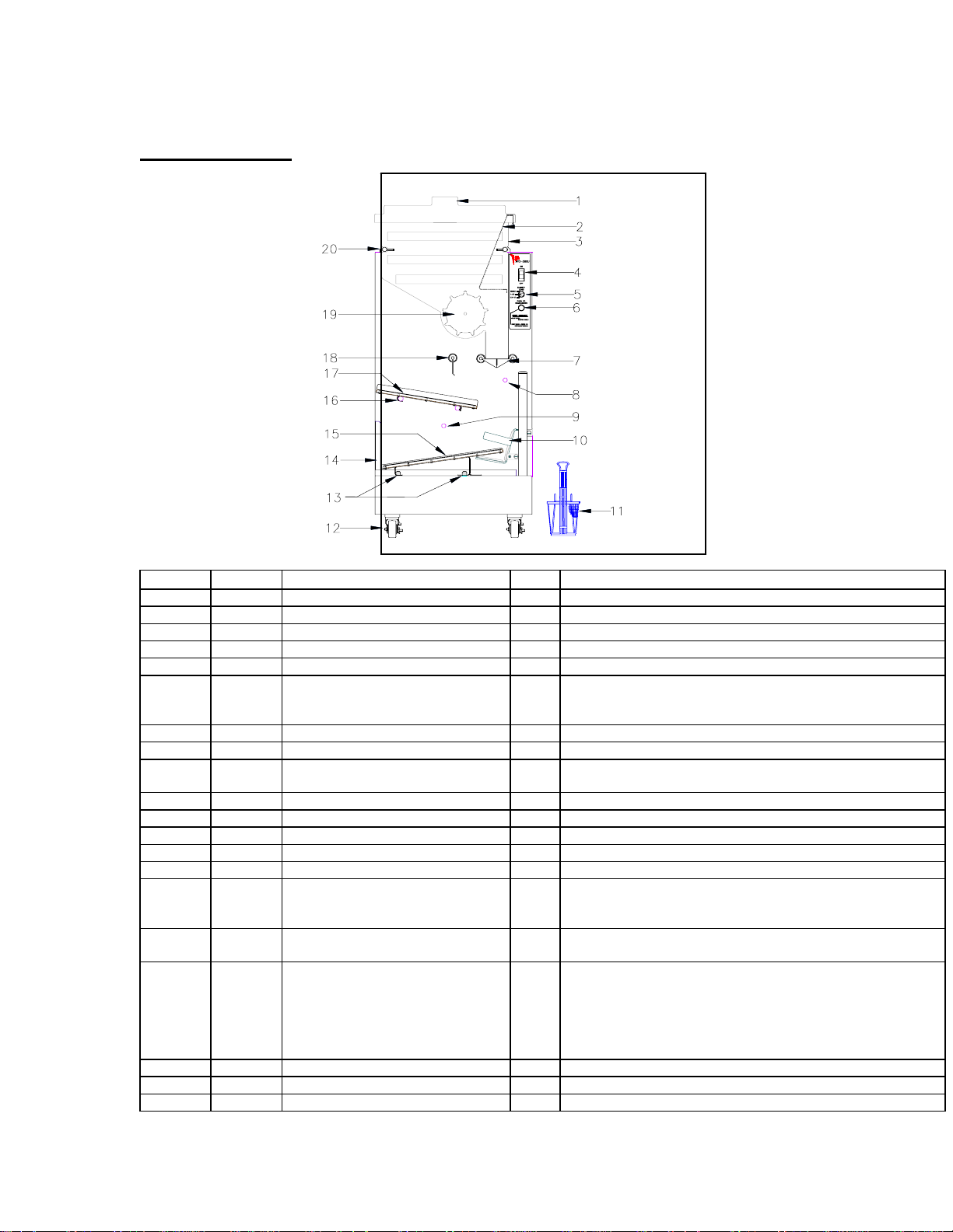
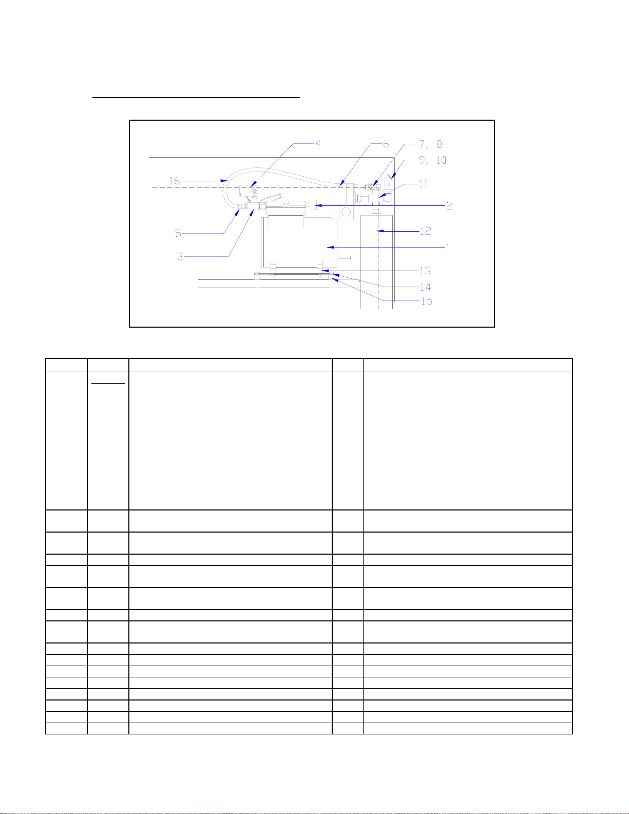
AFD-280, Front View
s
I
0
AFD-280 Front View
ITEM P/N DESCRIPTION NO. FUNCTION
1 202364 Hopper Lid 1 Cover for the Fry Hopper.
2 219129 Fry Diverter 1 Funnels fries to the Accumulator Doors area.
3 202368 Hopper 1 Holds frozen fries for dispensing into baskets.
4 213400 On / Off Switch with circuit breaker 1 On / Off Switch and A.C. circuit breaker.
5 215607 Selector Switch 1 Selects fry load sizes and Dispenser operation.
6 215606
290771
216489
7 --- Accumulator Doors Assembly -- See assembly illustration.
8 202038 Lift Sensor 1 Senses baskets in the Saddle when the Lift is raised.
9 202038 Guide Sensor 1 Senses baskets leaving the saddle and when the lower guide is
10 --- Saddle Assembly -- See assembly illustration
11 216258 Fry Basket 10 Receives fries from Dispenser.
12 216596 Front Casters with Brakes 2 Allows moving the Dispenser for cleaning & locking position.
13 290687 Locator Pins 2 Holds Drip Pan and Lower Guide in Place
14 202780 Drip Pan 1 Collects shortening and other waste materials.
15 202779
220494
290000
16 --- Upper Guide Support Bars,
17 220490
202476
202219
202044
202359
290000
18 --- Stopgate Assembly -- See assembly illustration
19 202366 Drum 1 Dispenses fries to the Accumulator Doors area.
20 220515 Hopper Support Bar, left 1 Holds the Hopper in proper orientation.
Start / Reset Push-button Switch
Lens Only
Bulb Only
Lower Guide Assembly
Lower Guide Ultem Runners
Runner Mounting Screws
(See Assembly Illustrations)
Upper Guide Assembly(centered pin)
-Fillister Screw (centered pin)
Upper Guide Assembly (offset pin)
-Fillister Screw (offset pin)
Upper Guide Ultem Runners
Runner Mounting Screws
1 Starts single basket cycle and resets system error.
full.
--
Entire Assembly
2
Basket slide rails.
12
Runner mounting screws. (6 screws per Ultem)
2 Secures the Upper Guide in the proper orientation.
--
No Longer Available
2
Locates Upper Guide Position. (centered Guide)
--
Entire Assembly.
2
Locates Upper Guide Position. (offset Guide)
2
Basket slide rails.
10
Runner mounting screws. (5 screws per Ultem)
Page 2

220520 Hopper Support Bar, right 1
Page 3
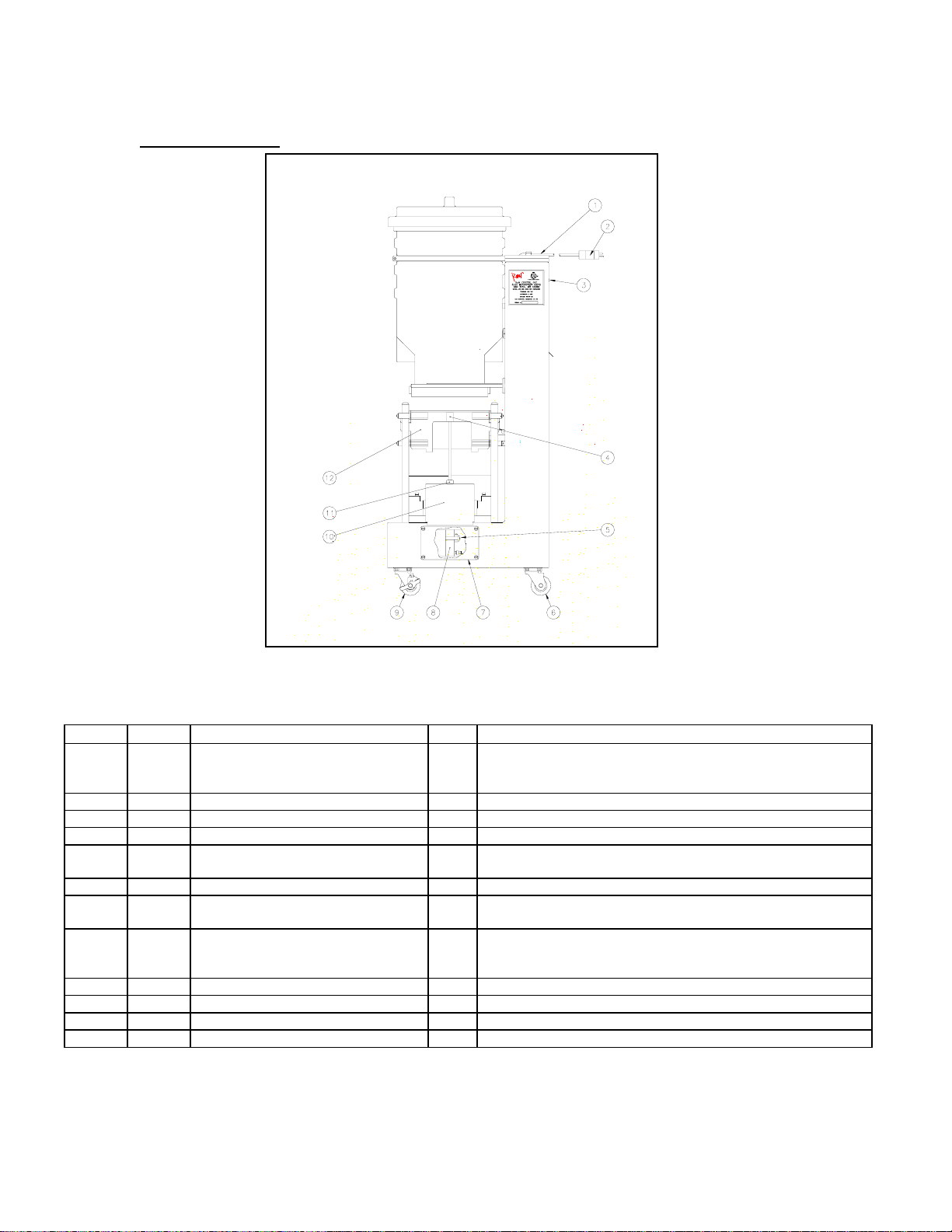
AFD-280 Side View
AFD-280 Side View
ITEM P/N DESCRIPTION NO. DETAILS
1 216692
202586
213942
2 202172 Molded Power Plug 1 Connects the Dispenser to the wall outlet.
3 213129 10-32 x 3/8” Machine Screw 1 Mounting Hardware for Rear Door
4 220507 Lift Cylinder Cap 1 Mounts to the end of the Lift Cylinder shaft.
5 202194
202516
6 216595 Rear Caster 2 Allows the dispenser to be moved for cleaning.
7 220491
202077
8 202055
202517
213369
9 216596 Front Caster with Brake 2 Allows dispenser movement and locks position.
10 220496 Lift Cylinder Cover 1 Protective cover for lift cylinder.
11 220497 Lift Cylinder Cover Nut 1 Secures protective cover.
12 --- Lift Saddle Assembly -- See assembly illustration
Power Cord Strain Relief
Washer
Nut
Lift Cylinder Switch
Lift Switch Sensor Band
Side Access Plate
Screws
Lift Cylinder
Lift Cylinder Lower Nut
Airline Fitting, 1/8" NPT M X 1/4"OD
1 Waterproof power cord inlet.
2 2 Detects lift cylinder down position.
Holds lift switch in place
1 4 Permits access to lower portion of lift cylinder.
Secures access plate to dispenser chassis.
1
Raises and lowers the lift saddle.
1
1
Page 4
AFD-280 Rear View
AFD-280 Rear View
ITEM P/N DESCRIPTION FUNCTION
1 202061
202190
202766
202765
2 --- Run “T” Assembly (No Longer Available) Head pressure vent system.
3 202196 Compressor Pressure Control Switch Control compressor: On at 40 psi, Off at 60 psi.
4 202197 Pressure Relief Valve Over pressure protection.
5 202199
219262
6 202861
202062
7 216044
202179
213509
213432
8 ---- Stopgate Assembly See assembly illustration
9 ---- Upper Guide Support / Alignment Assembly Upper guide support fixture and alignment.
10 202582 Pneumatic Manifold Assembly See assembly illustration
11 202051 Pressure Regulator Assembly Regulates System Air Pressure at 30 psi.
12 202449
216485
13 216595 Rear Caster Allows Dispenser to be moved for cleaning.
14 290626
290063
15 202038 Lower Guide Optical Sensor Detects baskets at the Lower Guide.
16 202038 Basket Lift Optical Sensor Detects baskets in the Lift Saddle when lift is raised.
17 290685 Load Cell replacement kit, including mounting hardware
18 ---- Accumulator Doors/ Load Cell Assembly See assembly illustration
19 202057 Accumulator Door Air Cylinder Assembly Pneumatic cylinder to operate the accumulator doors.
20 ---- Drum Motor Assembly See assembly illustration
Not
Shown
202377 Tubing Replacement Kit Kit to replace all the pneumatic tubing
Air Compressor, Ramped Valve, 110V, 60 Hz
Air Compressor, Ramped Valve, 220V, 50 Hz
Air Compressor, Ramped Valve, 220V, 60 Hz
Air Compressor, Ramped Valve, 100V, 50/60 Hz
Compressor Air Inlet Filter
Filter Media only
Air Reservoir Assembly
Mounting Clamps
Power Supply, International Power
Stand Off
Screw
Washer
Din Rail Terminal Assembly
Circuit Breaker
Plus Controller Board
E-prom
(1/4-20 x 5/8 cap screws and ¼” lock washers)
Provides compressed air for Dispenser operations.
Filters air going into the compressor
Filter media only.
Stores system compressed air.
Secures Air Reservoir to Dispenser chassis.
Provides 24.5 VDC for system operation.
See assembly illustration
See assembly illustration
Wiring terminal assembly. See assembly illustration
1.5 Amp Drum Motor circuit breaker.
Controls Dispenser electrical functions.
Programs the controller board.
Detects the weight of the Accumulator Assembly.
Page 5
AFD-280 Compressor Assembly, Style “A”
AFD-280 Compressor Assembly Style “A”
ITEM P/N DESCRIPTION NO. DETAILS
1 ---
202061
202190
202766
202765
203281
203296
2 202199
219262
3 --- Run “T” Assembly (No Longer Available) 1 Head Pressure Venting System. Replace with 203296
4 --- Airflow Bypass Solenoid (No Longer Available) -- Part of Run “T” Assembly, Item 3
5 202243 Check Valve 1 Part of Run “T” Assembly, Item 3
6 213477 Airline Fitting, 90°, 1/4” Push Tube 1 Part of Run “T” Assembly, Item 3
7 202196 Pressure Control Switch 1 Compressor Control Switch. See Note in item 1.
8 202197 Pressure Relief Valve 1 Part of Reservoir Assembly
9 213477 Airline Fitting, 90°, 1/4” Push Tube 1 Part of Reservoir Assembly
10 291324
291322
11 202861 Air Reservoir Assembly 1 Compressed air storage.
12 202065 Compressor Vibration Mounting 4 Vibration isolation.
13 220512 Compressor Mounting Plate 1 Mounting plate for compressor.
14 202091 Compressor Vibration Mounting 4 Vibration isolation.
15 202878 Airline, ¼ X 24” 24” Airline from compressor to reservoir.
Air Compressor
Air Compressor, Ramped Valve, 110V, 60 Hz
Air Compressor, Ramped Valve, 220V, 50 Hz
Air Compressor, Ramped Valve, 220V, 60 Hz
Air Compressor, Ramped Valve, 100V, 50/60 Hz
Ramped Valve Upgrade Kit
Run “T” Elimination Kit
Air Inlet Filter Assembly
Filter media only.
4-Way fitting
Nipple fitting, hex, 1/4" NPT
1
--
Compressed air source for Dispenser operations.
--
Note: Pressure Control Switch must be reset for 40-60
--
psi. (2.8-4.1Bar) operation.
-1
Compressor Upgrade kit:
Note: Must have Run “T” Elimination kit installed and
Pressure Control Switch reset for 40-60 psi. (2.8-
4.1Bar) operation.
1
Tubing and fittings to replace Run “T” assembly.
Note: Must have Ramped Valve Compressor and the
Pressure Control Switch must be reset for 40-60 psi
1 1 Compressor air inlet filter.
Replaceable filter media.
1 Part of Reservoir Assembly
Page 6
AFD-280 Compressor Assembly, Style “B”
AFD-280 Compressor Assembly, Style “B”
ITEM P/N DESCRIPTION NO. DETAILS
1
202061
202190
202766
202765
203281
203296
2 202199
219262
3 --- Run “T” Assembly (No Longer Available) 1 Head Pressure Venting System. Replace with
4 --- Airflow Bypass Solenoid (No Longer Available) -- Part of Run “T” Assembly, Item 3
5 213478 Airline Fitting, Straight, 3/8” Push Tube
6 202196 Pressure Control Switch -- Compressor Control Switch (On at 40 psi, 2.8 Bar,
7 216493 ¼” Push Tube Fitting 3/8” (¼” NPT Female) -- Part of Reservoir Assembly
8
291321
202243
9 202197 Pressure Relief Valve Part of Reservoir Assembly
10 291321 Elbow, 90° -- Part of Reservoir Assembly
11 291324 4-Way Fitting -- Part of Reservoir Assembly
12 202861 Air Reservoir Assembly 1 Compressed air storage.
13 202065 Compressor Vibration Mounting 4 Vibration isolation.
14 220512 Compressor Mounting Plate 1 Mounting plate for compressor.
15 202091 Compressor Vibration Mounting 4 Vibration isolation.
16 202482 Airline, 3/8 X 24” 24” Airline from compressor to reservoir.
Air Compressor
Air Compressor, Ramped Valve, 110V, 60 Hz
Air Compressor, Ramped Valve, 220V, 50 Hz
Air Compressor, Ramped Valve, 220V, 60 Hz
Air Compressor, Ramped Valve, 100V, 50/60 Hz
Ramped Valve Upgrade Kit
Run “T” Elimination Kit
Air Inlet Filter Assembly
Filter media only.
(¼” NPT male)
Elbow, 90°
Check valve
1
--
Compressed air source for Dispenser operations.
--
Note: Pressure Control Switch must be reset for 40-
--
60 psi. (2.8-4.1Bar) operation.
-1
Compressor Upgrade kit:
Note: Must have Run “T” Elimination kit installed
and Pressure Control Switch reset for 40-60 psi.
(2.8-4.1Bar) operation.
1
Tubing and fittings to replace Run “T” assembly.
Note: Must have Ramped Valve Compressor and the
Pressure Control Switch must be reset for 40-60 psi
1 1 Compressor air inlet filter.
Replaceable filter media.
203296
-- Part of Run “T” Assembly, Item 3
Off at 60psi, 4.1 Bar)
--
Part of Reservoir Assembly
--
Part of Reservoir Assembly
Page 7
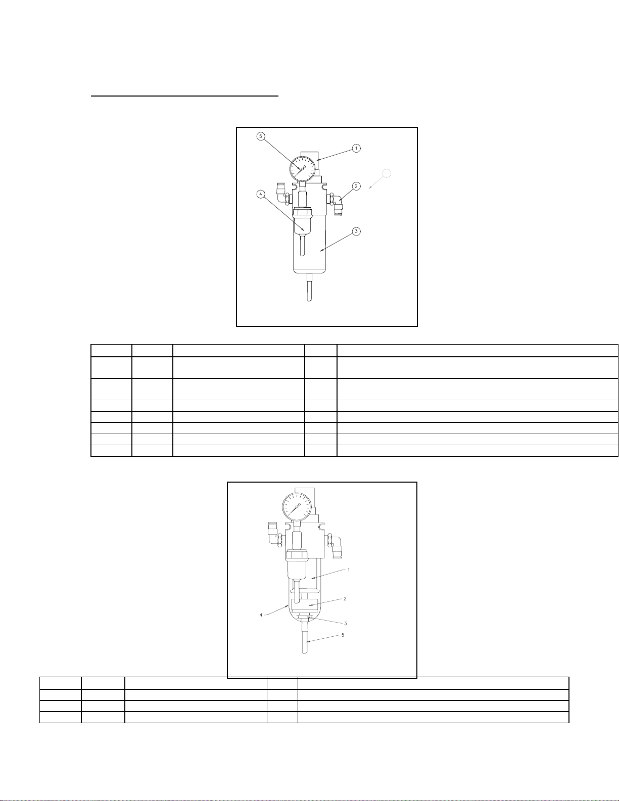
AFD-280 Pressure Regulator Assembly
6
Pressure Regulator Assembly p/n 202051
ITEM P/N DESCRIPTION NO. DETAILS
1 --- Pressure control knob. -- Pull up to unlock, turn to increase or decrease system pressure.
Set for 30 psi. Part of Pressure Regulator Assembly
2 213477 Airline fitting, 90° ¼” Push
Tube
3 --- Filter Bowl Cover Shield. -- Safety cover for the Filter Bowl. Part of Pressure Regulator Assembly.
4 202604 Air Present Switch 1 Senses system operating pressure, adjusted for 20 psi On.
5 202606 Air Pressure Gauge 1 Indicates regulator pressure setting.
6 213372 Regulator Mounting Screws 2 Secures the regulator to the back panel.
---- 202051 Pressure Regulator Assembly 1 Complete Filter Regulator assembly.
2 Airline Connection.
ITEM P/N DESCRIPTION NO. DETAILS
1 202614 Filter Media Replacement Kit 1 Removes contaminants from system air pressure.
2 --- Float Valve -- Part of Pressure Water Trap Bowl Assembly.
3 --- Drain Filter -- Part of Pressure Water Trap Bowl Assembly.
Page 8

4 202245 Water Trap Bowl and Drain Fitting 1 Collects and drains moisture from system air pressure.
5 202480 Drain Tube, 5/16" X 4 1/2" 4.5” Drains water from pressure regulator.
---- 202051 Pressure Regulator Assembly 1 Complete Filter Regulator assembly.
Page 9

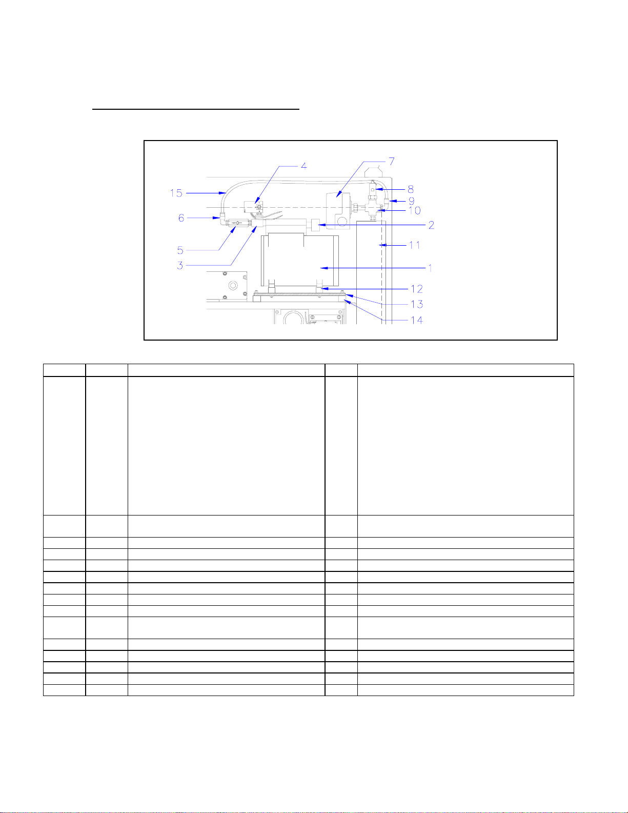
AFD-280 Manifold Assembly
LEFT SIDE VIEW REAR VIEW
Manifold Assembly p/n 202054 (replace with p/n 202582)
ITEM P/N DESCRIPTION NO. DETAILS
1 Pneumatic Manifold Assembly
Replace with part number 202582 and 2 screws
part number 213372.
2 213318 Airline Fitting, 90°, ¼” Push Tube, 1/8" NPT 1 Airline connection.
3 213320 Manifold Compressed Airline Input 1 Airline from the Pressure Regulator.
4 213369 Airline Fitting, Straight, ¼” Push Tube, 1/8" NPT 3 Airline connection.
5 202479 Manifold Output, OPEN Stopgate 1 BLUE Airline to top Stopgate Cylinder fitting.
6 202478 Manifold Output, CLOSE Stopgate 1 RED Airline to bottom Stopgate Cylinder fitting.
7 202481 Manifold Output, OPEN Accumulator Doors 1 CLEAR airline to top Accumulator Cylinder fitting.
8 202481 Manifold Output, CLOSE Accumulator Doors 1 CLEAR airline to bottom Accumulator Cylinder fitting.
9 213320 Manifold Output, RAISE Lift Cylinder 1 OPAQUE airline to fitting at bottom of Lift Cylinder.
10 203282 Airline Fitting, ¼”-Barbed 2 Airline connection.
11 213372 Allen Head Cap Screws, 10-32 x 2” 2 Secures Manifold Assembly to Dispenser chassis.
12 203294 Adjustable Vent, LOWER Lift Cylinder 1 Controls the DOWN SPEED of the Lift Cylinder.
13 202090 Airflow Adjustment, Stopgate OPEN “B” 1 Controls the opening speed of the Stopgate Cylinder.
14 202090 Airflow Adjustment, Stopgate CLOSE “A” 1 Controls closing speed of the Stopgate Cylinder.
15 202090 Airflow Adjustment, Accumulator OPEN “B” 1 Controls the opening speed of the Accumulator Doors.
16 202090 Airflow Adjustment, Accumulator CLOSE “A” 1 Controls the closing speed of the Accumulator Doors.
17 202021 Airflow Adjustment, Lift Cylinder UP speed 1 Controls the Lift Speed of the Lift Cylinder.
18 219010 Manifold Solenoid & manual activator. SV3 1 Activates the Stopgate airflow for OPEN & CLOSE.
19 219010 Manifold Solenoid & manual activator. SV2 1 Activates the Accumulator Doors airflow for OPEN &
20 219009 Manifold Solenoid & manual activator. SV1 1 Activates airflow to the Lift Cylinder to raise UP.
21 215468 Electrical Connector, 8 position. 1 Connects Solenoid Wiring to the Controller Board
22 202242 Manifold Vent 1 Exhausts manifold intermittent air pressures.
1 Distributes airflow to pneumatic cylinders.
CLOSE.
Outputs.
Page 10

AFD-280 Accumulator Doors / Load Cell Assembly
SIDE VIEW
REAR VIEW
Accumulator Doors / Load Cell Assembly
ITEM P/N DESCRIPTION NO. DETAILS
1 203282 Straight Fitting, 1/8 NPT Male-1/4 In. Barb 1 Airline fitting.
2 202057 Accumulator Doors Air Cylinder 1 Pneumatic actuator, opens and closes doors.
3
203283
203290
4 202068 Slide Rail 1 Allows Accumulator Assembly Motion / Sensing.
5 202073 Screws, Socket Head Cap ¼-20 X ¾” 3 Attaches Slide Rail to Dispenser Chassis.
6 220457 Carriage Plate 1 Attaches Accumulator Assembly to Slide Rail.
7 202173 Screws, M6 x 16mm 4 Secures Carriage Plate to Slide Rail
8 220464 Door Linkage 2 Accumulator Door Linkage.
9 220463 Connector Link 2 Interconnects Cylinder and Door Linkages.
10 220462 Cylinder Link 1 Linkage attached to end of Cylinder Shaft.
11 202082 Clevis Pin, 1/4” X 1” 6 Secures Linkages together.
12 202081 Hairpin Clip 6 Secures Clevis Pins.
13 213422 Flange Bearing 4 Bearing for Accumulator Door Shafts.
14 213356 Retaining Ring, E-Clip, ½” 4 Secures Accumulator Door Shafts.
15 220458 Bearing Plate 1 Part of Accumulator Door Chassis.
16 202048
213142
17 220461 Tie Rod 4 Spacer for Accumulator Chassis.
18 202045 Screw, Flat Head, ¼-20 X 1” 4 Secures Cylinder Plate to Accumulator Chassis.
19 220459 Cylinder Plate 1 Air Cylinder Mounting Plate.
20 220499
202214
21 220480
220475
22 290685 Load Cell (includes mounting hardware) 1 Detects weight of French Fries.
23 213143
213142
90° Barbed Fitting Assembly:
- 90° Elbow, 1/8 NPT Male to 10-32
- Barbed Fitting, 10-32 Male-1/8 In. Barb
Screws, Allen Head Cap ¼-20 X 3 ½”
Lock Washer, ¼”
Shaft Collar
Shaft Collar Set Screw, 8-32 X ½”
Accumulator Door, Left (not shown)
Accumulator Door, Right
Screws, Socket Head Cap, ¼-20 X ½”
Lock Washers, ¼”
Airline fitting assembly.
1
1
4 4 Secures Accumulator Chassis Assembly.
2 1 Protects inner Dispenser cabinet from contamination.
Secures Shaft Collar to Shaft
1 1 Accumulator door and shaft weldment, left hand.
Accumulator door and shaft weldment, right hand.
2 2 Secures Load Cell to Dispenser Chassis.
Page 11

24 202901 Accumulator Cylinder Jam Nut, 5/8” - 18 1 Locks Cylinder Shaft adjustment.
Page 12

AFD-280 Stopgate Assembly
SIDE VIEW
REAR VIEW
Stopgate Assembly
ITEM P/N DESCRIPTION NO. DETAILS
1 202056 Air Cylinder 1 Pneumatic actuator for the Stopgate.
2 213318 Airline Fitting, ¼” Push type elbow 2 Airline connection.
3 n/a Mounting Bracket, part of item #1 -- Secures the Pneumatic Cylinder to the Dispenser chassis.
4 213143 Socket Head Cap Screw, ¼-20 X ½” 4 Secures mounting bracket to the Dispense chassis.
5 202970
203092
6 n/a Clevis Pin, part of item #5 -- Secures Shaft Linkage to Door Linkage.
7 202176
213142
8 220466 Outer Bearing Plate 1 Mounting for Stopgate assembly.
9 220498 Stopgate Shaft Linkage 1 Linkage attached to Stopgate Door Shaft.
10 202082
202081
11 213422 Flange Bearings 2 Bearings for Stopgate Door Shaft.
12 202073
213142
13 220499
202214
14 220505 Stopgate Weldment 1 Welded Stopgate Door and Shaft assembly.
15 220461 Spacer Tie Rod 4 Provides proper spacing between the Bearing Plates.
16 202175 Inner Bearing Plate 1 Mounting for Stopgate assembly.
17 213356 Retaining ring, E-Clip, ½” 2 Secures Stopgate Shaft to Bearing Plates.
Cylinder Linkage and Clevis Pin
Cotter Pin
Bolt, ¼-20 X 3”
Lock Washer, ¼”
Clevis Pin, ¼” X 1”
Hairpin Clip
Socket Head Cap Screw, ¼-20 X ¾”
Lock Washer, ¼”
Shaft Collar
Shaft Collar Set Screw, 8-32 X ½”
1 1 Linkage attached to Air Cylinder Shaft.
Secures Clevis Pin.
4 4 Secures Outer and Inner Bearing Plates together.
1 1 Secures Linkage to Stopgate Door Shaft.
Secures the Clevis Pin.
2 2 Secures Stopgate Assembly to the Dispenser chassis.
1 1 Protects Dispenser inner cabinet from contamination.
Secures the Shaft Collar to the Stopgate Shaft.
Page 13

AFD-280 Lift Cylinder Assembly
FRONT VIEW
SIDE VIEW
12 3/16” Min.
12 1/4” Max.
Lift Cylinder Assembly
ITEM P/N DESCRIPTION NO. DETAILS
1 202194
202516
2 202055
202517
213369
3 220496 Lift Cylinder Cover, AFD-280 1 Protective cover for the Lift Cylinder.
4 202194
202516
5 220497 Lift Cylinder Cover Nut 1 Secures the Lift Cylinder Cover to the Dispenser.
6 220507 Lift Cylinder Cap, AFD-280 Screw On 1 Attaches to Lift Cylinder Shaft, contacts Lift Saddle.
7 202782 Lift Saddle Assembly 1 Transports the Baskets to the Lower Guide.
8 220456 Saddle Post 2 Guides the Lift Saddle
9 220491
202046
10 202066
213264
Lower Lift Cylinder Switch
Lift Cylinder Switch Mounting Strap
Lift Cylinder
Lift Cylinder Mounting Nut, ¾ -16
Airline Fitting, 1/8" NPT M X 1/4"OD
Upper Lift Cylinder Switch
Lift Cylinder Switch Mounting Strap
Lift Cylinder Access Plate
Screws, 10-32 X ¾”
Bolts, ½ -13 X 1 ½” , AFD-280
Lock Washer, ½”
1 1 Detects when the lift is in the down position.
Secures the switch to the cylinder.
1
Pneumatic cylinder which actuates the lift.
1
Secures the Lift Cylinder to the Dispenser chassis.
1
Airline connection.
1 1 Detects when the lift is in the up position.
Secures the switch to the cylinder.
1 4 Provides access to the lower Lift Cylinder Components.
Secures the access plate to the Dispenser body.
4 4 Secures the Saddle Posts to the Dispenser chassis.
Page 14

AFD-280 Saddle Assembly
SIDE VIEW
END VIEW
AFD-280 Assembly Number 202782
ITEM P/N DESCRIPTION NO. DETAILS
1 220468 Right Upper Wear Strip 1 Wear surface against the Guide Post.
2 220469 Right Lower Wear Strip 1 Wear surface against the Guide Post.
3 220469 Left Lower Wear Strip 1 Wear surface against the Guide Post.
4 220467 Left Upper Wear Strip 1 Wear surface against the Guide Post.
5 202064 Shoulder Bolt 4 Secures Guide Rollers to Saddle Assembly. Stainless Steel.
6 217810 Guide Roller 4 Roller for Saddle Assembly against the Guide Posts.
7 217805 Lift Saddle Weldment 1 Metal body of the Lift Saddle Assembly.
8 202046 Flat Head Screw, 10-32 X ¾” 6 Secures Wear Strips to Lift Saddle. Stainless Steel.
9 220472
or
202762
10 202047 Flat Head Screw, 10-32 X ½” 4 Secures Saddle Slides to the Lift Saddle.
11 220473 Splash Shield 1 Contains splashed materials within the Dispenser .
12 202047 Flat Head Screw, 10-32 X ½” 5 Secures Splash Shield to Lift Saddle.
Saddle Slide, 5” length, 4 3/8” hole
spacing
Saddle Slide, 4 ¾” length, 3 ½” hole
spacing
2
Wearable sliding surface for Baskets to slide on. The
correct part number is determined by the length of the strip
2
and the hole spacing..
Page 15

AFD-280 Drum Motor Assembly
TOP VIEW
LEFT SIDE VIEW
Drum Motor Assembly
ITEM P/N DESCRIPTION NO. DETAILS
1 215228 Drum Motor Bearing Block 1 Bearing, Bearing Housing Assembly
2 292546 Drum Motor / Gear Box Assembly 1 24 VDC Gearmotor
3 213136 Socket Head Cap Screws, 10-32 x 1-1/4” 4 Secures Drum Motor to Bearing Block
4 213143
213142
5 220511 Drum Motor Shaft 1 Turns the Drum in the Hopper.
6 220508
202072
7 213911 Retaining ring, E-clip 2 Secures Drum Shaft.
8 ------ Drum Motor Electrical Connections 2 DC Gearmotor power input connections.
Socket Head Cap Screws, ¼-20 x ½”
Lock Washer ¼”
Drum Motor Shaft Collar
Shaft Collar Set Screw
4 4 Secures Bearing Block to Dispenser Chassis.
1 1 Prevents contamination of Dispenser cabinet.
Page 16

AFD-280 Optical Sensors
Sick Optical Sensor, 2 per Dispenser
Optical Sensor (Sick Electro Optics) (No longer available. Use Banner sensor)
ITEM P/N DESCRIPTION NO. DETAILS
1 202038 Optical Sensor, SICK 2 Sensor for Lift and Guide Basket detection locations.
2 220492 Sensor Mounting Bracket 2 Mounts / Locates the Optical Sensor.
3 213143
213142
213141
4 202619 Sensor Window Kit 2 Sensor protective window.
5 --- Sensor Output LED Indicator -- Turns ON with object detection.
6 --- Sensitivity / Gain Adjustment -- Gain Adjustment.
Bolt ¼ -20 X ½”
Lock Washer, ¼”
Flat Washer ¼”
4
Secures Mounting Bracket to Dispenser Back Panel.
4
4
Banner Optical Sensor, 2 per Dispense r
Optical Sensor (Banner)
ITEM P/N DESCRIPTION NO. DETAILS
1 202038 Optical Sensor, Banner 2 Sensor for Lift and Guide Basket detection locations.
2 220492 Sensor Mounting Bracket 2 Mounts / Locates the Optical Sensor.
3 213143
213142
213141
4 202619 Sensor Window Kit 2 Sensor protective window.
5 --- Sensor Output LED Indicator -- Turns ON with object detection.
6 --- Sensitivity / Gain Adjustment -- Gain Adjustment.
Bolt ¼ -20 X ½”
Lock Washer, ¼”
Flat Washer ¼”
4
Secures Mounting Bracket to Dispenser Back Panel.
4
4
Page 17

AFD-280 24.5 Volt Power Supplies
120 VAC, 50-60 Hz. 220 VAC, 50-60
Hz.
Linear Power Supply p/n 216044
ITEM P/N DESCRIPTION NO. DETAILS
1 -- AC Line Input -- AC Line Voltage
2 -- Jumper Wire -- Transformer jumper.
3 -- VDC Negative Output -- 24 VDC Negative output connection.
4 -- VDC Positive Output -- 24 VDC Positive output connection.
5 -- Vout Adjustment Potentiometer -- Adjusts Power Supply DC Output to 24.5 VDC
--- 216044 Power Supply, International Power, 3.6 A 1 24.5 VDC Power Supply
---- 215473 2 Position Connector Plug 1 Connects Power to Controller Board
Switching Power Supply p/n 202493 (No longer available, call for information)
ITEM P/N DESCRIPTION NO. DETAILS
1 --- A.C. Power Supply, Line Input -- AC Line Connection Point.
2 --- A.C. Power Supply, Line Input -- AC Line Connection Point.
3 --- Power Supply Ground Connection -- Power Supply AC Ground Connection.
4 --- D.C. V- Output -- Negative DC output connection point.
5 --- D.C. V+ Output -- Positive DC output connection point.
Page 18

6 --- Vout adjustment. -- 24.5 VDC voltage output adjustment potentiometer.
7 --- Output Indicator LED -- LED is ON when VDC is present at output terminals.
8 --- Power Supply, ETA, 3.2A 1 Power Supply, 24.5 VDC output, 95-240 VAC input.
---- 215473 2 Position Connector Plug 1 Connects Power to Controller Board
AFD-280 Din Rail Terminal , Circuit Breaker Assembly
DIN Rail Terminal Assembly
ITEM P/N DESCRIPTION NO. DETAILS
1 202036 Terminal End Plate 1 Electrical isolation.
2 216485 Circuit Breaker, 1.5 A, Thermal 1 Drum Motor protection.
3 213605 Din Rail End Anchor 2 Secures Din Rail components together.
4 202035 Jumper Clip, 15A 2 Configures terminal wiring inter-connections.
5 213373
213182
6 202033
202034
7 --- Wiring from 24.5 VDC Power Supply -- Dispenser wiring harness.
8 --- Wiring to Lift Optical Sensor -- Dispenser wiring harness.
9 --- Drum Motor Wiring -- Dispenser wiring harness.
10 --- Lower Guide Optical Sensor Wiring -- Dispenser wiring harness.
11 --- 24.5 VDC to Controller Board -- Dispenser wiring harness.
Din Rail
Truss Head Screw, 8-32 X 3/8”
Grounding Terminal Block, Green
Isolated Terminal Block, Grey
1 2 Mount for Din Rail components.
Secures Din Rail Mount to Dispenser Chassis.
1 3 Grounded wiring terminals.
Isolated wiring terminals.
Page 19

Page 20

AFD-280 Upper Guide Assembly
Note: The first 175 units manufactured in 1995 have centered pin guides. Newer units have the offset pin
guides.
Upper Guide Assembly, Centered Pin (Item 1) p/n 220490
(No longer available. Shown for reference only)
ITEM P/N DESCRIPTION NO. DETAILS
2 220489 Basket Runners, Ultem 2 Slide runners for baskets.
3 290000 Ultem Screws 16 Mounting screws for the Ultem runners.
Upper Guide Assembly, Offset Pin (Item 1) p/n 202219
ITEM P/N DESCRIPTION NO. DETAILS
2 202359 Basket Runners, Ultem 2 Slide runners for baskets.
3 290000 Ultem Screws 10 Mounting screws for the Ultem runners.
Page 21

AFD-280 Upper Guide Support Assembly
Note: The first 175 units manufactured in 1995 have centered pin guides. Newer units have the offset pin
guides.
AFD-280, Centered Guide Pin, (Item 4)
ITEM P/N DESCRIPTION NO. DETAILS
1 220503 Upper Guide Post Mounting Plate 1 Guide Post Mount
2 220501 Upper Guide Post (No Longer Available) 1 Post to which the Upper Guide is mounted.
3 220502 Upper Guide Post (No Longer Available) 1 Post to which the Upper Guide is mounted.
4 202476 Fillister Head Screw , 5/16- 18 x 1/2 ” 2 Locates Upper Guide on Mounting Posts
5 202073 Socket Head Cap Screw, 1/4-20 X 3/4” 4 Adjusts Mounting Plate positioning.
6 213539
213142
7 202174
213264
Socket Head Cap Screw, 1/4-20 X 1”
Lock Washer, 1/4”
Socket Head Bolt, 1/2” X 1-1/4”
Lock Washer, 1/2”
4 4 Secures Mounting Plate to Dispenser Chassis
2 2 Secures Upper Guide Posts to Mounting Plate
AFD-280 Offset Guide Pin, (Item 4)
ITEM P/N DESCRIPTION NO. DETAILS
1 220503 Upper Guide Post Mounting Plate 1 Guide Post Mount
2 202218 Upper Guide Post 1 Post to which the Upper Guide is mounted.
3 202218 Upper Guide Post 1 Post to which the Upper Guide is mounted.
4 202044 Fillister Head Screw ,1/4-20 X 1/2” 2 Locates Upper Guide on Mounting Posts
5 202073 Socket Head Cap Screw, 1/4-20 X 3/4” 4 Adjusts Mounting Plate positioning.
6 213539
213142
7 202174
213264
Socket Head Cap Screw, 1/4-20 X 1”
Lock Washer, 1/4”
Socket Head Bolt, 1/2-13 x 1-1/4”
Lock Washer, 1/2”
4 4 Secures Mounting Plate to Dispenser Chassis
2 2 Secures Upper Guide Posts to Mounting Plate
Page 22

AFD-280 Lower Guide
Lower Guide Assembly p/n 202779 (Item 1)
ITEM P/N DESCRIPTION NO. DETAILS
2 220494 Basket Runners, Ultem 2 Slide runners for baskets.
3 290000 Mounting Screws 12 Mounting Screws
 Loading...