

Page 1
MANUFACTURED
EXCLUSIVELY FOR
McDONALD'S
BY
Automated Equipment LLC
5140 Moundview Drive
Red Wing, Mn 55066
Phone: 1 (651) 385-2273
Fax: 1 (651) 385-2166
http://www.autoequipllc.com
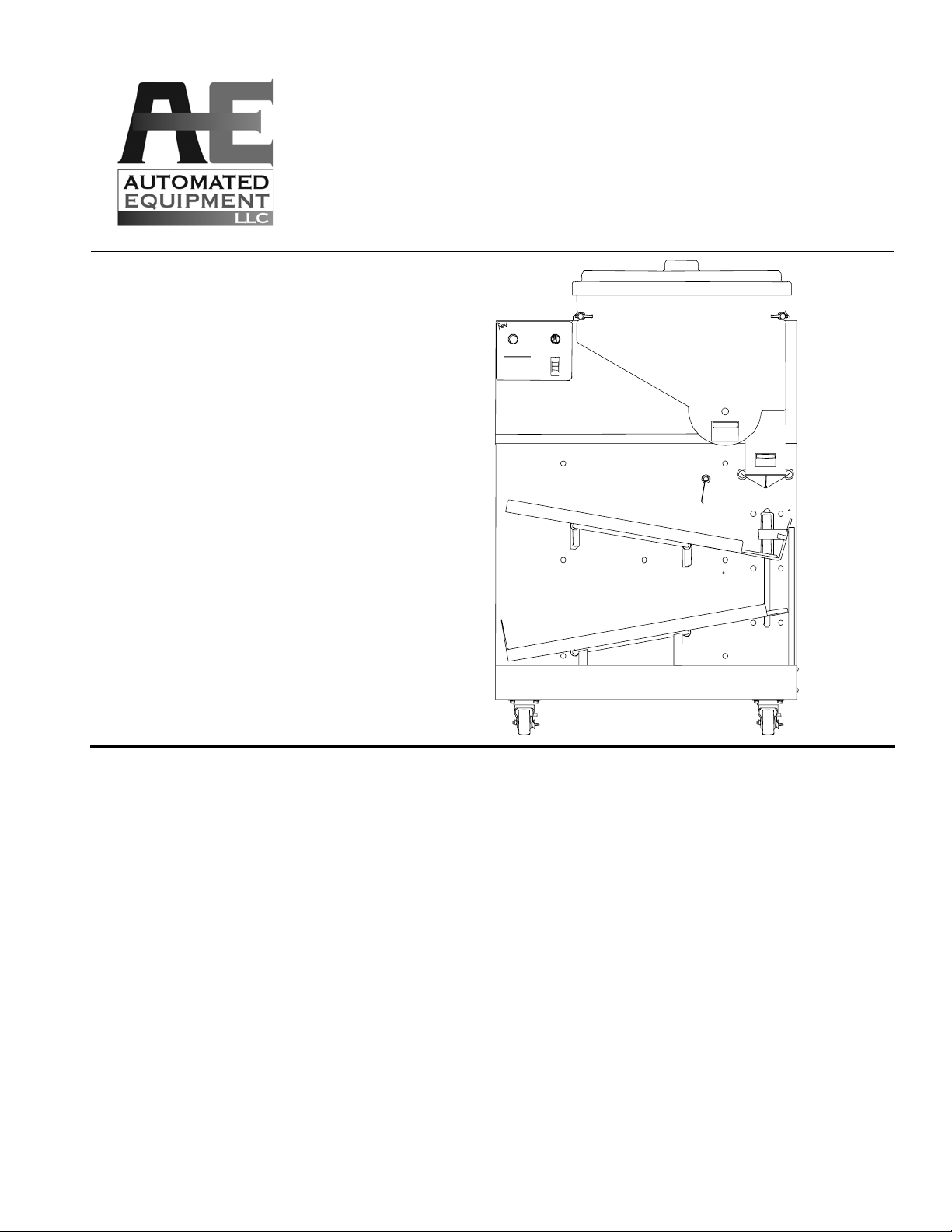
MODEL AFD-200
Arch Fry Dispenser
EQUIPMENT MANUAL
p/n 202089
ARCH FRY DISPENSER AFD-200
PUSH TO:
BASKET
RAM CENTER, INC.
1-800-248-ARCH
LOADS
POWER
ON
OFF
START/RESET
ERROR MESSAGE S
LOW BLINK-HOPPER EMPTY
AST BLINK- SYSTEM ERROR
RED WING, MN 55066
CAUTION
BASKETS
ARE HOT
WARNING
PINCH HAZARD
KEEP HANDS AWAY
FROM ACCUMULATOR
DOORS
For Service Call
1 (800) 248-2724
After hours, your call will be handled by a
pager service. A Technical Support
Representative will return your call.
TABLE OF CONTENTS
AFD 200 - WARRANTY................................................................................................................2
INTRODUCTION...........................................................................................................................3
SPECIFICATIONS ........................................................................................................................3
INSTALLATION INSTRUCTIONS ................................................................................................4
PARTS IDENTIFICATION AND FUNCTION.................................................................................5
SET-UP AND CLOSE PROCEDURES.........................................................................................9
SYSTEM FUNCTIONS AND OPERATION...................................................................................10
BASKET LOAD ADJUSTMENTS.................................................................................................10
TROUBLESHOOTING..................................................................................................................11
ORDERING PARTS/SERVICE .....................................................................................................14
NON-SCHEDULED MAINTENANCE............................................................................................15
PREVENTATIVE MAINTENANCE................................................................................................18
DIAGRAMS...................................................................................................................................20
Copyright © 2005 Automated Equipment LLC All Rights Reserved
Page 2

AFD 200 - WARRANTY
SERVICE PROVIDED
Automated Equipment LLC (hereinafter "AELLC"),
warrants the purchased product to be free from
manufacturing defects in material and workmanship
under normal use and conditions for the period and
component specified below:
Components covered Term
Pneumatic Components 1 year
Electronic Circuit Board Assemblies 1 year
Electrical and Mechanical Moving Parts 1 year
Structural frame work or enclosures 1 year
Lift Saddle Assembly 90 days
Guide Assemblies 90 days
Quick Coupler 90 days
Fry Baskets 90 days
The Warranty period commences on the date of
shipment for the Arch Fry Dispenser (hereinafter
"Product").
EXCEPT AS OTHERWISE PROVIDED HEREIN
AELLC MAKES NO OTHER WARRANTIES,
EXPRESS OR IMPLIED AND SPECIFICALLY
DISCLAIMS ANY WARRANTY OF
MERCHANTABILITY OR FITNESS FOR A
PARTICULAR PURPOSE.
AELLC will provide 1 (1) year of Warranty Service and
toll free phone technical support to Purchaser. If the
Product fails to perform during the warranty period and
such failure is covered by this warranty, AELLC shall
repair or replace, at its option, the Product to restore it
to normal operating condition. AELLC shall make all
reasonable efforts to perform such repairs during
normal working hours Monday through Friday,
however, AELLC is not responsible for delays or
failures in performance of such services caused by
Acts of God, failure of transportation, accidents, labor
strikes, shutdowns or work stoppages or other causes
beyond AELLC's control.
Warranty service performed herein is provided through
AELLC's technical support department or other
authorized service agent. Purchaser's unauthorized
use of any service personnel or other unauthorized
repair will immediately invalidate this warranty.
Replacement parts will be new or rebuilt parts or
components. Purchaser is responsible for costs to
return damaged warranted components to AELLC for
credit. AELLC parts and components not returned to
AELLC after thirty (30) days of Purchaser's receipt of
replacement parts or components from AELLC will be
invoiced for the full spare part or component purchase
price.
AELLC shall not be liable for any direct, indirect,
consequential damages (including damages for loss of
business profits, business interruption, loss of
business information and the like) arising out of the
use of or inability to use the Product.
THIS WARRANTY IS VOID IF THE PRODUCT IS
NOT FUNCTIONING CORRECTLY DUE TO ABUSE
OR NEGLECT BY THE PURCHASER, ITS EMPLOYEES, AGENTS, OR OTHER REPRESENTATIVES
EITHER BY BREAKING, BENDING, MISUSE,
ABUSE, DROPPING, ALTERATION, IMPROPER
MAINTENANCE OR ANY OTHER FORM OF
NEGLECT OR IMPROPER USAGE, THIS
WARRANTY DOES NOT COVER DAMAGE TO THE
PRODUCT CAUSED BY NATURAL CAUSES SUCH
AS LIGHTNING, ELECTRICAL CURRENT
FLUCTUATIONS, FLOOD, FIRE, TORNADOES, OR
OTHER ACTS OF GOD. AELLC WILL INVOICE
PURCHASER FOR REPAIRS MADE NECESSARY
BY THE HEREIN LISTED CAUSES.
This warranty is non-transferable and applies only to
the original Purchaser. This warranty is valid only in
the United States of America.
Purchaser will assure that the Product will receive
normal preventive maintenance and adjustments
necessary to keep the Product in good operating
condition pursuant to guidelines provided by AELLC.
THIS WARRANTY WILL NOT COVER DAMAGE TO
THE PRODUCT WHICH OCCURS DUE TO
PURCHASER'S FAILURE TO PROPERLY MAINTAIN
AND MAKE ORDINARY ADJUSTMENTS REQUIRED
FOR PROPER OPERATION OF THE PRODUCT.
Copyright © 2005 Automated Equipment LLC All Rights Reserved
2
Page 3

INTRODUCTION
SPECIFICATIONS
The Arch Fry Dispenser is a compact automated
system that replaces manual basketing of Fries and
the equipment that goes with it. The Arch Fry
Dispenser automatically weighs 1 pound (0.45 kg), or
1.5 pound (0.68 kg), loads of frozen French Fries and
dispenses them into the Fry Baskets.
The Arch Fry Dispenser's Hopper 42 lbs. (19 kg) of
frozen fries prior to Basket Loading. A rotating
Dispenser Drum inside the Hopper transfers the frozen
fries onto the Accumulator Doors where an electronic
Load Cell accurately weighs the French Fries.
Empty Fry Baskets are placed on the Upper Guide.
The Fry Baskets slide under the Accumulator Doors
where French Fries are dispensed into them. The
Basket Lift then lowers the filled Fry Baskets onto the
Lower Guide where the Fry Baskets wait to be picked
up by a crew person.
The Arch Fry Dispenser is usually positioned to the
right of an existing fry station and requires 36 linear
inches (92 cm) of floor space. 10 modified Fry
Baskets are provided with this equipment.
NOTE: This piece of equipment is made in America
and has American sizes of hardware. All hardware
metric conversions are approximate and can vary in
size.
HAZARD COMMUNICATION STANDARD (HCS) The
procedures in this manual include the use of chemical
products. These chemical products will be highlighted
with boldface letters followed by the abbreviation
(HCS) in the text portion of the procedure. See the
HCS Manual for the appropriate material safety data
sheets (MSDS).
The Arch Fry Dispenser consists of the following
components:
• Arch Fry Dispenser 200
• 10 Fry Baskets (Modified)
• 100 feet (30 meters) of Air Line
• 8 foot (2.5 meter) electrical cord for standard outlet
Optional Equipment:
• Oilless Air Compressor
• End Panel
• Replacement/Extra Fry Baskets
Electrical Requirements:
120 VAC, 15 Amp
Compressed Air Requirements:
2.0 CFM @ minimum of 80 PSI (5.4 bar)
Space Requirements:
Clear floor space near fry vat at least 36 inches
(92 cm) wide and 24 inches (60 cm) deep.
Basket Handles will extend to 29 inches (74 cm)
Arch Fry Dispenser:
Bulk storage of 42 lbs. (19 kg) of frozen French
Fries
Electrically and pneumatically (air) driven.
Equipped with swivel casters.
Handles up to 10 Fry Baskets.
Disassembles for cleaning.
Copyright © 2005 Automated Equipment LLC All Rights Reserved
3
Page 4

INSTALLATION INSTRUCTIONS
L
e
S
s
G
s
U
e
S
e
O
l
H
d
FAS
S
A
1-800-ROBOTIC
R
R
E
S
P
OFF
O
00
S
O
CCUMU
G
Air Compressor Installation and Start-up
If you have purchased an Air Compressor from AELLC, you will
want to install it before you put the Arch Fry Dispenser into position.
1. Choose a suitable location for the Compressor. The
Compressor requires a standard 120 VAC outlet,. If you have an
existing Compressor you may wish to place this Compressor in the
same area.
NOTE: Do not place compressor above or near items that must
remain dry. The compressor requires weekly purging, and will spray
a small quantity of water when purged.
2. Connect the Air Line to the Compressor.
ASSEMBLING THE ARCH FRY DISPENSER
per at or Pane
top Gat
pper Guid
uide Hook
haf t Col lar
ower Guid
opper Li
AFD-2
RCH FRY DISPENSER
BASKET
USH TO:
TART/RESET
LOADS
RROR MESSAGES
POWER
LOW BLINK-HOPPER EMPTY
T BLINK-SYSTEM ERROR
N
AM CENTER, INC.
ED WING, MN 55066
CAUTI O
BASKET
ARE HOT
WARNIN
PINCH HAZARD
KEEP HANDS AWAY
FR
M A
LATOR
DOORS
Locki ng Pi ns
Hopper
Fr y D iverter
Dr um
Basket Sensor
Li ft Dovetail
Li ft Saddl e
Basket Sensor
1. Place the hooks of the Lower Guide between the Shaft
Collars and push the guide to the LEFT to lock it in place.
3. Run the Air Line from the Compressor to a location
approximately 3 feet (1 meter) above the floor on the wall behind the
Arch Fry Dispenser location. You may wish to use the gas line
chase (if provided) to run the Air Line.
4. Pull an extra 6 feet (2 meters) of Air Line to allow the Arch
Fry Dispenser to move around while connected.
CAUTION: Do NOT connect the Air Line to the Arch Fry Dispenser
at this time. The Arch Fry Dispenser has a self-purging water trap in
it. If the Air Line is connected to the Arch Fry Dispenser before the
Compressor is at full pressure, the purge valve may remain open,
which will prevent the Compressor from building pressure and may
damage the Compressor.
5. Turn the Compressor ON and allow the Compressor to
reach FULL pressure.
6. Verify that the air valve on the compressor (if there is one)
is in the OPEN position.
The AELLC supplied Air Compressor operation switch should
remain in the AUTOMATIC position.
2. Place the hooks of the Upper Guide between the Shaft
Collars and push the guide to the RIGHT to lock it in place.
3. Install the Lift Saddle on the Lift Dovetail. Make sure the
Lift Saddle is completely seated.
4. Find the square opening in one end of the Dispenser
Drum.
5. Place the Dispenser Drum in the Hopper, aligning the
square opening on the Dispenser Drum with the hole in the back of
the Hopper.
6. Grasp the Hopper so that the hole is toward the Arch Fry
Dispenser.
7. Align the indentations on the Hopper with the Hopper
Support Bars.
8. Push the Hopper forward onto the Hopper Supp ort Bars
until the Drum Motor shaft touches the Dispenser Drum.
9. Rotate the Dispenser Drum (CLOCKWISE or
COUNTERCLOCKWISE) while applying gentle pressure to the
Hopper until you can slide the Hopper fully onto the Hopper Support
Bars. Do not force the Hopper back, you may damage the
Dispenser Drum.
10. Lock the Hopper onto the Arch Fry Dispenser by pressing
the Locking Pins towards each other.
11. Place the Fry Diverter in the Hopper.
12. Place the Hopper Lid on the Hopper.
13. Verify the Compressor pressure is
at least 80 PSI (5.4
bar).
14. Verify that air valve on compressor is open.
15. Connect the Air Line to the back of the Arch Fry Dispenser
by pushing the Quick Coupler onto the Coupler Nipple until it is
secure.
NOTE: The Arch Fry Dispenser has a self-purging water trap in it. If
the Air Line is connected to the Arch Fry Dispenser before the
Compressor is at full pressure, the purge valve may remain open,
which will prevent the Compressor from building pressure.
Copyright © 2005 Automated Equipment LLC All Rights Reserved
4
Page 5
16. Plug the Power Cord into a wall outlet.
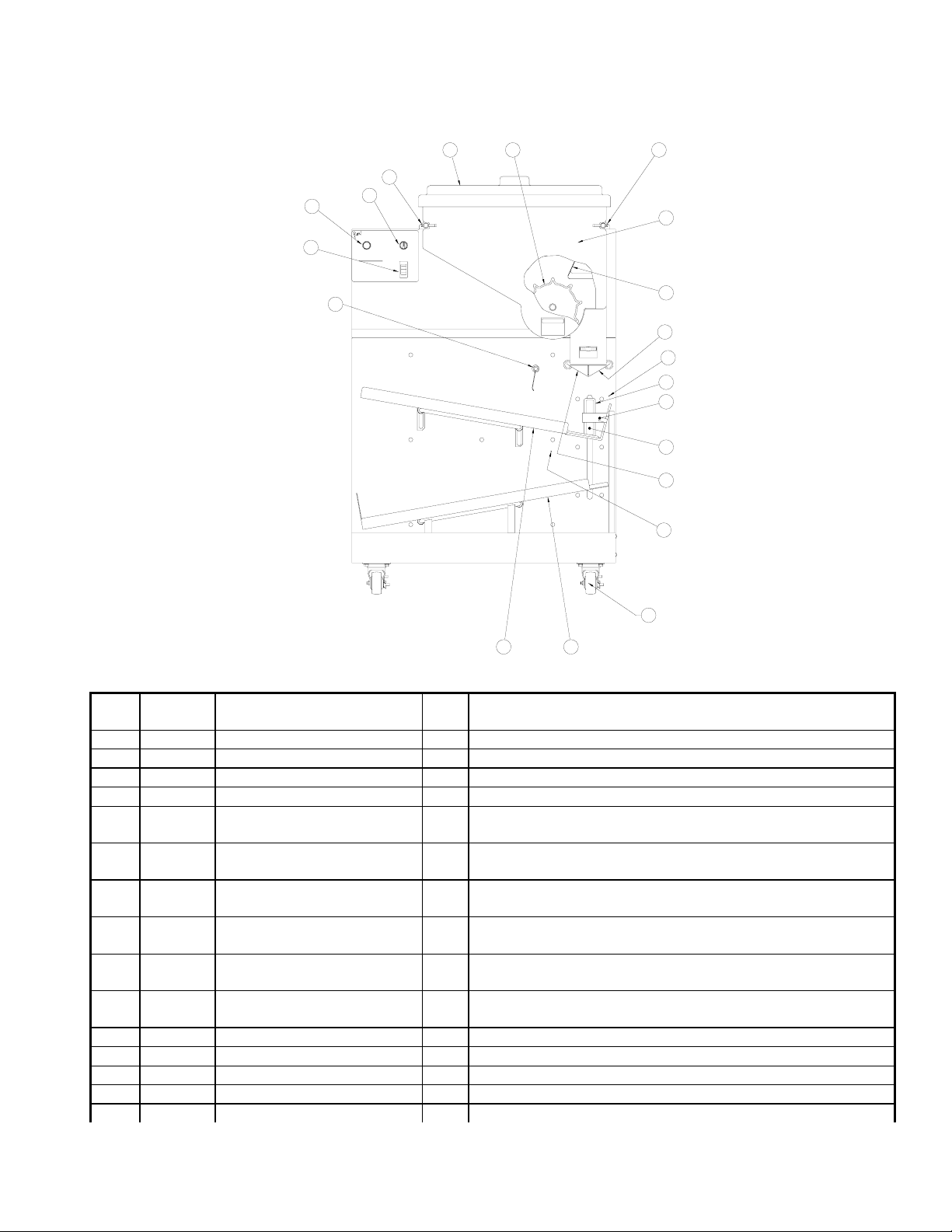
PARTS IDENTIFICATION AND FUNCTION
2 4
14
18
21
20
AFD-200
ARCH FRY DISPENSER
PUSH TO:
BASKET
LOADS
START/RESET
ERROR MESSAGES
POWER
SLOW BLINK-HOPPER EMPTY
FAST BLINK-SYSTEM ERROR
8
RAM CENTER, INC.
RED WING, MN 55066
1-800-ROBOTIC
ON
OFF
CAUTION
BASKETS
ARE HOT
WARNING
PINCH HAZARD
KEEP HANDS AWAY
FROM ACCUMULATOR
DOORS
13
1
3
10
16
12
7
11
9
17
15
6
5
Arch Fry Dispenser (FRONT VIEW)
Item Part
Description Qty Function
Number
1 213267 Hopper 1 Holds frozen Fries until they are portioned into Fry Baskets.
2 213268 Hopper Lid 1 Covers the frozen Fries in the Hopper.
3 213277 Fry Diverter 1 Funnels uncooked Fries to the accumulator area.
4 213278 Dispenser Drum 1 Dispenses bulk uncooked Fries to the accumulator area.
5 216645
216024
6 216081
216055
7 215971
215961
Lower Guide
Lower Guide Ultem
Upper Guide
Upper Guide Ultem
Lift Saddle
Saddle Skids
1
Provides a smooth surface for filled Fry Basket staging.
2
Removable for cleaning.
1
Provides a smooth surface for empty Fry Basket movement
2
towards the Basket Lift. Removable for cleaning.
1
Carries Fry Baskets from the Upper Guide to the Lower
2
Guide.
8 213473 Pre-Stage Stop Gate 1 Holds Fry Bask ets on the Upper Guide when the Basket
Lift is not in the UP position.
9 213641 Accumulator Door (L) 1 Holds weighed Fries from the Hopper until a Fry Basket is
in position to receive them.
10 213642 Accumulator Door (R) 1 Holds weighed Fries from the Hopper until a Fry Basket is
in position to receive them.
11 213900 Lift Dovetail 1 Attachment for Lift Saddle.
12 215948 Carriage Guide-white nylon 1 Provides slip for Lift Dovetail on Arch Fry Dispenser face.
13 215951 Hopper Support Bar (Right) 1 Guides the Hopper on and off of the Arch Fry Dispenser.
14 216018 Hopper Support Bar (Left) 1 Guides the Hopper on and off of the Arch Fry Dispenser.
15 216596 Brake Caster - Front 2
Allows the Fry Dispenser to be locked into place. (Bolted style)
Copyright © 2005 Automated Equipment LLC All Rights Reserved
5
Page 6
215965 Brake Caster – Front 2
Allows the Fry Dispenser to be locked into place. (Threaded style)
16 213254 Fiber Optic Sensor #1 1 Detects when a Fry Basket is in position to receive a load
of Fries.
17 213254 Fiber Optic Sensor #2 1 Detects when the Lower Guide is full of Fry Baskets and
when a Fry Basket has left the Lift Saddle.
18 215606 Lighted Button (Green) 1 Start/ Reset Button.
19 216489 Bulb (not shown) 1 Replacement bulb for lighted Button.
20 215607 Three Position Switch 1 Selects the Fry Load Size
21 213400 Power Switch (Orange) 1 Turns the Dispenser ON and OFF
1
NOTICE
SET PRESSURE
2
SWITCH TO 50 PSI
3
4
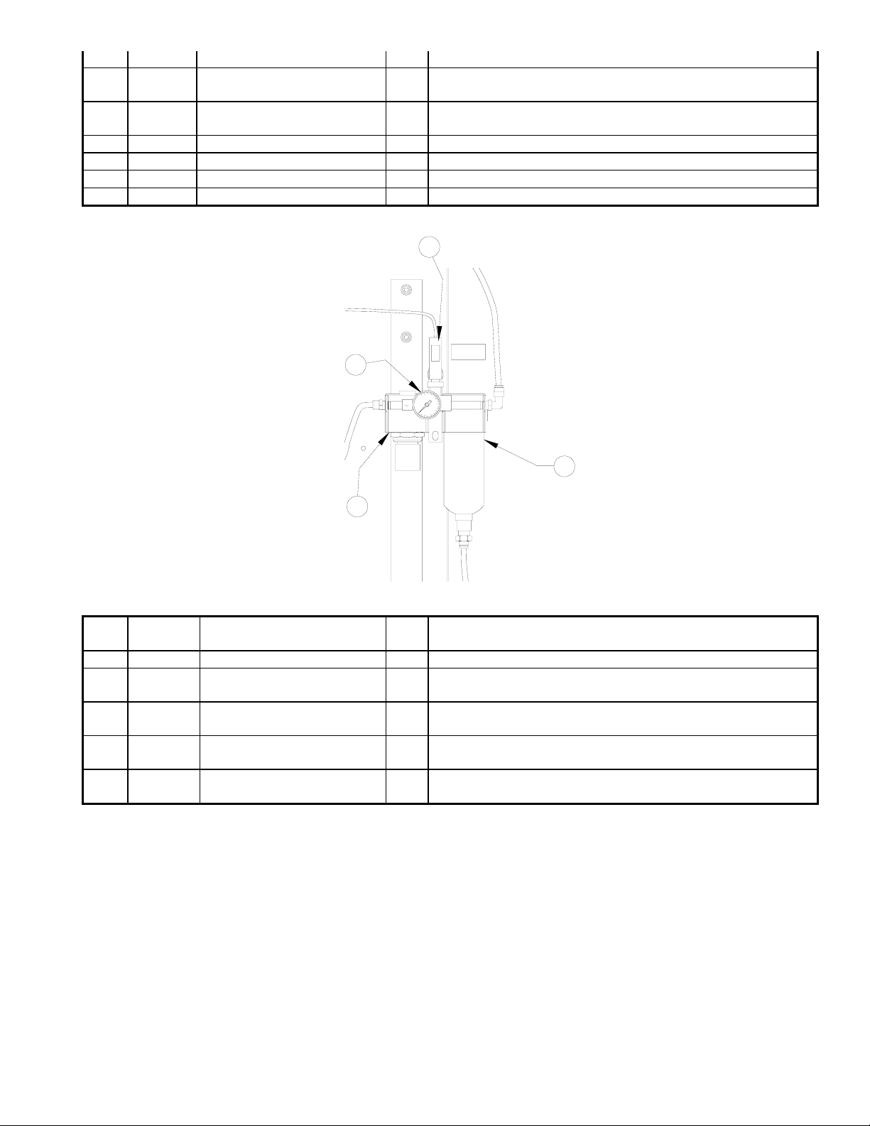
AIR FILTER/REGULATOR (Part Number 202250)
Item Part
Description Qty Function
Number
1 included Pressure Switch 1 Monitors the air pressure, and detects a loss of pressure.
2 202606 Pressure Gauge 1 Displays the current system pressure. Assists in adjusting
the regulator.
3 202245 Mist Separator with Auto
Drain – Watts (Black)
3 290095 Mist Separator with Auto
Drain – SMC (Gray)
1 Automatically drains water and debris from the Air Line that
may cause damage to the Arch Fry Dispenser.
1 Automatically drains water and debris from the Air Line that
may cause damage to the Arch Fry Dispenser.
4 included Pressure Regulator 1 Regulates 80 PSI (5.4 bar) pressure from the 90-120 PSI
(6 - 8 bar) Compressor.
Copyright © 2005 Automated Equipment LLC All Rights Reserved
6
Page 7
18
1
2
14
12
17
16
15
13
11
3
4
5
1.5
6
NOTICE
SET PRESSURE
SWITCH TO 50 PSI
7
8
9
10
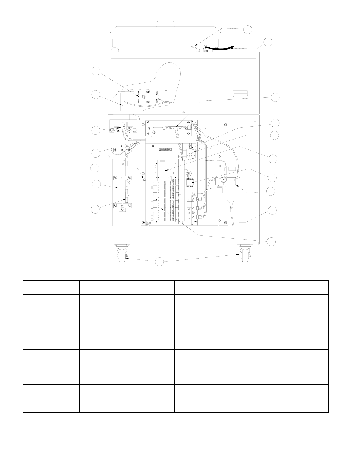
Arch Fry Dispenser (REAR VIEW)
Item Part
Description Qty Function
Number
1 213609
213610
213478
Quick Coupler Nipple
Quick Disconnect
Quick Disconnect Fitting
1
1
1
Connection point for the air line from the compressor.
Disconnects airline from the dispenser.
Adapts airline to quick disconnect.
2 202172 Power Cord 1 Supplies the Arch Fry Dispenser with power from the wall
3 216089 Stop Gate Cylinder 1 Air-operated cylinder that activates the stop gate.
4 213365 Fiber Optic Amplifiers #1-
#2
2 Generates a red light for sensors #1-#2, and controls the
sensitivity of the sensors, and inputs Fry Basket present
to control card.
5 216485 1.5 AMP Circuit Breaker 1 Protects the fry Drum Motor from electrical overload.
6 213367 Load Cell Board 1 Translates information from the Load Cell into data that
the Arch Fry Dispenser I/O Board computer can
understand.
7 213924 Solid State Relay 1 Provides high current drive to the drum motor.
8 202250 Filter/Regulator Assembly 1 Controls and monitors the pressure of the air supplied to
the Arch Fry Dispenser.
9 203985 4-Stack Air Valve Manifold 1 Air valves that control cylinders in the Arch Fry
Dispenser.
Copyright © 2005 Automated Equipment LLC All Rights Reserved
7
Page 8

10 203984 Dispenser I/O Board 1 Computer that controls the I/O (input and output) of the
Arch Fry Dispenser.
11 216595 Caster 2
215960 Caster 2
Allows Fry Dispenser to be moved for cleaning. (Bolted style)
Allows Fry Dispenser to be moved for cleaning. (Threaded style)
12 213107 Lift Cylinder Switches 2 Indicates the position of the Basket Lift mechanism.
13 290688 Lift Cylinder 1 Air-operated cylinder that moves the Lift Saddle in both
UP and DOWN directions.
14 213254 Fiber Optic Sensor #1 1 Optic Sensor Head that detects baskets in the lift.
15 213254 Fiber Optic Sensor #2 1 Optic Sensor Head that detects baskets leaving the lift.
16 290686 Accumulator Door Cylinder 1 Air-operated cylinder that opens and closes the
Accumulator Doors.
17 203983 Load Cell 1 Electronic device that converts weight to an electrical
signal.
18 292546 Drum Motor 1 Turns the Dispenser Drum that moves the bulk uncooked
Fries into the accumulator area.
Air Line
Item Part
Description Qty Function
Number
1 213610 Quick Coupler 1 Mate for Quick Coupler Nipple on Arch Fry Dispenser.
2 213478 3/8" OD tube x 1/4" NPT 1 Connects the air supply line to the Quick Coupler body.
3 216482 Tubing, Nylon Reinforced,
3/8 In. O.D (100ft)
1 Supplies the Arch Fry Dispenser with air from a
compressor.
Miscellaneous Parts (Not Shown)
Part
Description Qty Function
Number
202002 E-Prom, Loader, 3.25R 1 Software for Dispenser I/O Board.
216044 24V Power Supply 1 Provides control voltage for dispenser operation.
219007 Lighted Button Lens Cap
1 Replacement lens cap for lighted button.
(Idec Switch Only)
213914 Screws, Lift Dovetail 4 Attaches Lift Dovetail to Lift Cylinder.
216055 Upper Guide Slide 2 Slide Mechanism for Baskets.
216024 Lower Guide Slide 2 Slide Mechanism for Baske t s.
290000 Screws, Slide 26 Attaches slide to guides.
216258 Fry Basket 10 Receives dispensed fries for cooking.
Copyright © 2005 Automated Equipment LLC All Rights Reserved
8
Page 9

SET-UP AND CLOSE PROCEDURES
Daily Set-Up
1. Verify the Compressor pressure is
PSI (5.4 bar).
2. Connect the Air Line to the back of the Arch
Fry Dispenser by pushing the Quick Coupler onto the
Coupler Nipple until it is secure.
NOTE: The Arch Fry Dispenser has a self-purging
water trap in it. If the Air Line is connected to the Arch
Fry Dispenser before the Compressor is at full
pressure, the purge valve may remain open, which will
prevent the Compressor from building pressure.
3. Verify that the Power Switch is in the OFF
position.
4. Plug the Power Cord into a wall outlet.
5. Load the Hopper with frozen French Fries.
DO NOT SHAKE OR DROP the Fries into the Hopper.
6. Turn the Load Select Switch to the desired
load weight.
7. Fill the Upper Guide with empty Fry Baskets.
at least 80
5. Check that the Accumulator Doors are empty
of Fries.
6. Disconnect the Air Line from the back of the
Arch Fry Dispenser by grasping the collar on the Quick
Coupler and pulling back until it releases from the
Coupler Nipple.
NOTE: Disconnecting the Air Line from the Arch Fry
Dispenser every day is an important part of
Preventative Maintenance. Releasing the air pressure
allows the self-purging water trap to drain, thus
preventing the water from getting into the system.
7. Disconnect the Power Cord from the electrical
outlet.
8. Remove the Fry Diverter by grasping it and
pulling it UP.
9. Slide the Locking Pins outward to release the
Hopper.
10. Remove the Hopper (and the Dispenser Drum
inside) by pulling the Hopper OUT and AWAY from the
Hopper Support Bars.
11. Remove the Upper Guide assembly by sliding
it to the LEFT then lifting it straight UP.
8. Turn the Power Switch to the ON position
(illuminated).
9. Press the Start/Reset Button. Automatic
basket loading will begin at the load weight selected.
10. Use filled Fry Baskets from the Lower Guide
for French Fry production.
11. Return each empty Fry Basket to the Upper
Guide for refilling after the cooking cycle is complete.
Daily Closing
1. Turn the Power Switch to the OFF position.
2. Remove all Fry Baskets from the upper and
Lower Guides. Discard and record the uncooked
Fries.
3. Remove the Hopper Lid by lifting it straight UP
and OFF of the Hopper.
4. Discard and record any Fries remaining in the
Hopper at closing.
12. Remove the Lift Saddle by grasping the back
support bar with both hands and lifting straight UP.
13. Remove the Lower Guide assembly by sliding
it to the RIGHT then lifting straight UP.
14. Take the hardware removed from the Arch Fry
Dispenser to the back sink. Wash it in a hot solution of
McD APC (HCS), and sanitize. Wipe dry.
NOTE: Do NOT roll the dispenser to the back sink for
cleaning, this will cause unnecessary wear on the
dispenser.
15. Wipe down the Arch Fry Dispenser with a hot
solution of McD APC (HCS) and water. Repeat wipedown with clear water to rinse away cleanser residue.
NOTE: Do NOT spray down the dispenser. It is not
sealed, and contamination may get into sensitive
components.
16. Dry all parts and reassemble the Arch Fry
Dispenser.
Copyright © 2005 Automated Equipment LLC All Rights Reserved
9
Page 10

SYSTEM FUNCTIONS AND OPERATION BASKET LOAD ADJUSTMENTS
E
B
The following switches and buttons are located on the
Operator Panel:
ARCH FRY DI SPENSER
PUSH
ST ART /RES
ERROR MESSAGES
SLOW BLINK-HOPPER EMPTY
FAST BLI NK-REFER TO
EQUIPMENT MANUAL
FOR SERV I CE CALL
1-800- 248-2724
OFF/SI NGL
1-LB
1.5- L
AFD- 200
BA SKET
LOADS
POWER
ON
OFF
POWER SWITCH (Orange)
Supplies electrical power to the Arch Fry Dispenser. It
illuminates when the Arch Fry Dispenser has power.
LOAD SELECT SWITCH
Slight increases or decreases in Basket Load weights
are possible by re-positioning the yellow Basket Load
Offset ADJUSTMENT switches (located behind the
OPERATOR PANEL). Adjusting these switches
allows the crew to increase or decrease the load
weight 2, 4, or 6 ounces beyond either the 1 pound
(0.45 kg) or 1.5 pound (0.68 kg) setting. Once the
switches are re-positioned, the Arch Fry Dispenser will
continually basket the new weight until they are
changed.
NOTE: Adjusting the load weight above 1.5 pounds
(0.68 kg) is NOT recommended for proper cooking.
SWITCH NUMBER TS1 TS2 TS3
Normal Setting OFF OFF INCR
Increase 2 oz. (57 gm) ON OFF INCR
Increase 4 oz. (113 gm) OFF ON INCR
Increase 6 oz. (170 gm) ON ON INCR
Decrease 2 oz. (57 gm) ON OFF DEC
R
Decrease 4 oz. (113 gm) OFF ON DEC
R
Decrease 6 oz. (170 gm) ON ON DEC
R
It has 3 positions that allow the operator to select
Basket Load weights and control operation.
OFF/SINGLE: Stops automatic Fry Basket
loading. Press the Start/Reset Button to dispense
only 1 Fry Basket of Fries pre-set to 1.5 pounds.
1 LB: Position for continual dispensing of 1 pound
(0.45 kg) Basket Loads.
1.5 LB: Position for continual dispensing of 1.5
pound (0.68 kg) Basket Loads.
START/RESET BUTTON (Green)
Press to start the loading of a single Fry Basket when
the Load Select Switch is set for OFF/SINGLE.
Press to start automatic loading of Fry Baskets when
the Load Select Switch is set for 1 or 1.5 lb. (0.45 or
0.68 kg) loads.
Press to reset a System Error.
Copyright © 2005 Automated Equipment LLC All Rights Reserved
10
Page 11

TROUBLESHOOTING
The status of the Arch Fry Dispenser is displayed in the Start/Reset Button light. When the Hopper is filled and
operating normally, the Start/Reset Button remains steadily illuminated. System Errors appear as a flashing green
light on the Operator Panel. System Errors are a result of incorrectly assembling the Arch Fry Dispenser, or an
interruption in the normal operation.
In the following charts, the PROBLEM columns contain a list of problems that may occur, the PROBABLE CAUSE
column describes why the problem may have appeared; and the CORRECTIVE ACTION column describes the action
that must be taken to eliminate the problem. If after performing the procedure listed under CORRECTIVE ACTION
you have not corrected the problem, call AELLC Service for assista nce.
NOTE: Press the Start/Reset Button after correcting the problem.
PROBLEM PROBABLE CAUSE CORRECTIVE ACTION
Restart Button is
flashing slowly.
Fries have formed a “bridge” over
Hopper Drum is not locked onto
Restart Button Compressor is not running Check that compressor has power and is turned on.
begins flashing
immediately when
Dispenser is
turned on.
Air Pressure is below 60 PSI (4.0
Pressure switch is faulty. Contact AELLC Service
There is an air leak. Check the main Air Line, Compressor, and Arch Fry
Basket Loads are
consistently light
or heavy. The Hopper is touching the
The Load Cell is improperly
The Load Cell has malfunctioned. Contact AELLC Service.
Basket Loads
suddenly change.
The Hopper is empty. Refill the Hopper with Fries. Remove any empty Fry
The Fry Diverter is not properly
The Hopper is touching the
Dispenser Drum is
not rotating
Hopper is empty (Restart Button
Hopper is empty Fill the Hopper with Fries.
Remove the Hopper Lid and re-distribute the Fries inside.
the drum.
Remove the Hopper Lid and Fry Diverter. Turn the
the shaft.
Dispenser Drum, while applying pressure and slide it fully
onto the shaft. Re-install the Fry Diverter and Hopper Lid.
Air Line is not connected to the
Connect the Air Line to the Dispenser.
Dispenser.
Compressor has not been
allowed to charge before Air Line
was connected
Disconnect the Air Line from the Dispenser. Wait until the
compressor reaches full pressure (compressor will turn
itself off). Reconnect Air Line.
Adjust the compressor to maintain between 90 and 120
bar)
PSI (6 and 8 bar). If you need assistance, contact AELLC
Service
Dispenser for leaks. If you are unable to find it, or need
assistance repairing it, contact AELLC Service
Basket Load Offset switches were
not set properly.
Verify proper switch settings. Re-position the switches if
necessary.
Re-assemble the Hopper. No objects, other than Fries,
Accumulator Doors.
may touch the Accumulator Doors.
Refer to the Load Cell Calibration procedure in the noncalibrated.
Fries have formed a “bridge” over
scheduled maintenance section.
Remove the Hopper Lid and redistribute the Fries.
the drum.
Baskets from the Lower Guide and place them on the
Upper Guide.
Remove and re-install the Fry Diverter.
installed.
Re-assemble the Hopper. No objects, other than Fries,
Accumulator Doors.
may touch the Accumulator Doors.
The accumulator doors are full. The Dispenser Drum will rotate only when the accumulator
doors require more Fries.
Fill the Hopper with Fries. The Dispenser Drum will rotate
is flashing slowly).
when the next empty Fry Basket is cycled through the
Upper Guide.
Copyright © 2005 Automated Equipment LLC All Rights Reserved
11
Page 12

NOTE: Press the Start/Reset Button after correcting the fault condition.
PROBLEM PROBABLE CAUSE CORRECTIVE ACTION
Dispenser Drum is
not rotating (cont.)
The Dispenser has detected a
Hopper Drum is not locked onto
Fries have formed a “bridge” over
the drum (Restart Button is
flashing slowly).
SYSTEM FAULT (Restart Button
is flashing rapidly).
the shaft.
Remove the Hopper Lid and re-distribute the Fries inside.
The Dispenser Drum will rotate when the next empty Fry
Basket is cycled through the Upper Guide.
Continue troubleshooting. If the accumulator doors need
Fries, the Dispenser Drum will continue rotating when the
Restart Button is pressed.
Remove the Hopper Lid and Fry Diverter. Turn the
Dispenser Drum, while applying pressure and slide it fully
onto the shaft. Re-install the Fry Diverter and Hopper Lid.
The Hopper is touching the
Accumulator Doors.
The Fry Diverter fell inside the
Hopper preventing the Dispenser
Re-assemble the Hopper. No objects, other than Fries,
may touch the Accumulator Doors.
Remove the Fry Diverter from inside the Hopper and
install correctly.
Drum from turning.
The Drum Motor Circuit Breaker
(CB1) has tripped.
The Fry Basket sensors are dirty
or covered with shortening.
The Load Cell is improperly
calibrated.
Remove the LOWER BACK panel. Reset the Circuit
Breaker by pushing IN the black button labeled 1.5.
Turn off the Power Switch. Clean the sensors with a hot
wet towel.
Refer to the Load Cell Calibration procedure in the non-
scheduled maintenance section.
The Load Cell has malfunctioned. Contact AELLC Service.
Fry Basket is filled
more than once.
Shortening build-up on Sensors
blocked the sensor from detecting
a Fry Basket.
Turn off the Power Switch. Clean the sensor with a HOT
wet towel. Place an empty Fry Basket on the Lift Saddle.
Restart the Arch Fry Dispenser to see if sensor #2 detects
the Fry Basket and operation resumes.
A Fry Basket is positioned
Re-position the Fry Basket in the Lift Saddle.
incorrectly on the Lift Saddle.
Fry Baskets are
sticking or tipping
on Upper or Lower
Fries, crumbs, or shortening have
accumulated on the Guide or Lift
Saddle.
Turn the Power Switch off, and clean the Guide and Lift
Saddle with a hot towel.
Guide. A Fry Basket is bent or damaged. Replace the damaged Fry Basket.
The Lift Saddle is assembled
Re-assemble the Lift Saddle correctly.
incorrectly.
The guide is not assembled
correctly.
Re-assemble the guide. If the guide locating Collars are
loose, adjust the Collars so that the guide has equal
spacing to the nylon runners on the Lift Saddle.
The Lift Saddle or Guide is bent
Contact AELLC Service.
or damaged.
Hopper Compressor is not running Check that compressor has power and is turned on.
Accumulator
Doors do not shut
Compressor has not been
Air Line is not connected to the
Dispenser.
allowed to charge before Air Line
was connected
Connect the Air Line to the Dispenser.
Disconnect the Air Line from the Dispenser. Wait until the
compressor reaches full pressure (compressor will turn
itself off). Reconnect Air Line.
There is an air leak. Check the main Air Line, Compressor, and Arch Fry
Dispenser for leaks. If you are unable to find it, or need
assistance repairing it, contact AELLC Service
The Accumulator Door Cylinder
Tighten the bolts holding the cylinder cross bar in place.
actuator is loose.
Copyright © 2005 Automated Equipment LLC All Rights Reserved
12
Page 13

NOTE: Press the Start/Reset Button after correcting the fault condition.
PROBLEM PROBABLE CAUSE CORRECTIVE ACTION
Fry Basket stop Compressor is not running Check that compressor has power and is turned on.
gate does not hold
Fry Baskets in
place. Compressor has not been
Air Line is not connected to the
Dispenser.
allowed to charge before Air Line
was connected
Connect the Air Line to the Dispenser.
Disconnect the Air Line from the Dispenser. Wait until the
compressor reaches full pressure (compressor will turn
itself off). Reconnect Air Line.
There is an air leak. Check the main Air Line, Compressor, and Arch Fry
Dispenser for leaks. If you are unable to find it, or need
assistance repairing it, contact AELLC Service
One of the Fry
Basket sensors is
OFF. The Power
Switch lamp is ON.
Does not dispense
fries into a waiting
basket.
The Sensor or Amplifier has
failed.
The power supply is not
functioning properly.
Shortening build-up on sensor #1
blocked the sensor from detecting
a Fry Basket.
Turn off the Dispenser and contact AELLC Service.
Turn off the Dispenser and contact AELLC Service.
Turn off the Power Switch. Clean the sensor with a HOT
wet towel. Place an empty Fry Basket on the Lift Saddle.
Restart the Arch Fry Dispenser to see if sensor #1 detects
the Fry Basket and operation resumes.
A Fry Basket is positioned
Reposition the Fry Basket in the Lift Saddle.
incorrectly on the Lift Saddle.
No light is coming from Sensor. Contact AELLC Service.
SYSTEM ERROR
(Restart Button
flashes rapidly) as
lift reaches top or
bottom
The Basket Lift cylinder speed is
either too fast or too slow.
A tipped Fry Basket stopped the
Basket Lift.
Refer to the Maintenance Section of this manual for the
procedure to adjust the Basket Lift cylinder speed.
Remove the Fry Basket. Check it to be sure that it is not
bent or damaged. Clear the Lift Saddle of any Fries or
shortening. Press the restart button. If problem re-occurs,
remove and re-assemble the guides.
Some shortening on Sensor #1 or
#2 blocked the sensor from
Clean the sensors with a HOT wet towel. Press the restart
button.
detecting a Fry Basket.
Compressor is not running Check that compressor has power and is turned on.
Air Line is not connected to the
Connect the Air Line to the Dispenser.
Dispenser.
There is an air leak. Check the main Air Line, Compressor, and Arch Fry
Dispenser for leaks. If you are unable to find it, or need
assistance repairing it, contact AELLC Service
Lift Cylinder Switches not working Contact AELLC Service
Lift Cylinder Failure Contact AELLC Service
Copyright © 2005 Automated Equipment LLC All Rights Reserved
13
Page 14

ORDERING PARTS/SERVICE
Warranty service is initiated by calling AELLC's
TECHNICAL SUPPORT HOT LINE at 1-800-248-
2724. Technical Support personnel will determine the
cause of failure and recommend solutions. If parts are
required, the parts will be shipped directly to the
restaurant. A local service agent will be dispatched
once the problem has been identified and parts have
been shipped.
Record the following information for your records:
Date of Installation:
Service Agency Telephone:
When repairing this unit, use only replacement parts
supplied by AELLC. Use of replacement parts other
than those supplied by AELLC will void the warranty.
All shipping charges are F.O.B. AELLC, and are
subject to change without notice. Prices will be those
in effect at the time of shipment. AELLC reserves the
right to make suitable substitutions in materials,
depending upon their availability.
Parts Location and Ordering Information
Use the
Parts Identification and Function section in
this manual to help you identify the correct part
number and quantity of items to order.
Copyright © 2005 Automated Equipment LLC All Rights Reserved
14
Page 15

NON-SCHEDULED MAINTENANCE
This section gives the procedures for several repairs
that do not require special tools.
REPLACEMENT OF WATER TRAP BOWL
3. Remove the lower back panel of the Arch Fry
Dispenser.
4. Ensure at least 80 PSI (5.4 bar) is being
supplied to the Filter/Regulator.
5. Pull DOWN on the black adjustment knob
located below the air pressure gauge.
Parts: Water trap bowl
1. Turn the main Power Switch for the Arch Fry
Dispenser to the OFF position.
2. Remove the Fry Baskets from the Arch Fry
Dispenser.
3. Disconnect the Air Line from the back of the
Arch Fry Dispenser by grasping the collar on the
Quick Coupler and pulling back until it releases from
the Coupler Nipple.
CAUTION: Failure to remove the system air
pressure could result in injury.
4. Remove the lower back panel of the Arch Fry
Dispenser.
5. Make sure the air pressure gauge reads 0 PSI
on the regulator inside the Arch Fry Dispenser.
6. Pull down on the thumb clip that locks the
water trap bowl and by turning it to the LEFT. The
plastic bowl will come off by pulling down on the guard.
7. Remove the old bowl. Insert the new water
trap bowl into the metal guard. Ensure that the O-ring
is located on TOP of the bowl.
6. Turn the knob COUNTERCLOCKWISE to
decrease air pressure and CLOCKWISE to increase
air pressure. Adjust the air pressure to 80 PSI
(indicated on the gauge) by turning the knob.
7. Push UP on the knob to lock it in place.
8. Replace the lower rear panel.
9. Plug the Power Cord into the wall outlet.
10. Move the Arch Fry Dispenser back into
position.
11. Turn the ARCH Fry Dispenser Power Switch
to the ON position.
RESETTING THE DRUM MOTOR CIRCUIT
BREAKER.
WARNING: ELECTRICAL SHOCK HAZARD!
Keep hands and tools away from all electrical
components.
1. Turn the Arch Fry Dispenser main Power
Switch to the OFF position.
2. Unplug the ARCH Fry System from the wall
outlet.
8. Replace the guard and bowl assembly on the
Filter/Regulator unit by pushing up and turning it to the
RIGHT.
CAUTION: Hand-tighten only!
9. Reconnect the main Air Line to the Quick
Coupler. Check for leaks. Replace the outside cover.
ADJUSTING FILTER/REGULATOR AIR
PRESSURE SETTING
1. Turn the Arch Fry Dispenser Power Switch to
the OFF position.
2. Disconnect the electrical power plug from the
wall outlet.
Copyright © 2005 Automated Equipment LLC All Rights Reserved
3. Remove the LOWER BACK PANEL of the
Arch Fry Dispenser.
4. Locate the Circuit Breaker. If the Start/Reset
Button on the breaker has popped out (tripped,
showing white), reset the breaker by pushing the
BLACK button IN.
5. Re-install the LOWER BACK PANEL.
6. Verify that the Dispenser Drum and Fry
Diverter are installed properly.
7. Plug the Power Cord into the wall outlet.
8. Turn the main Power Switch to the ON
position.
15
Page 16

9. If the breakers trip again, turn the Power
Switch to the OFF position, unplug the Arch Fry
Dispenser from the wall outlet, and call AELLC for
service.
Copyright © 2005 Automated Equipment LLC All Rights Reserved
16
Page 17

ADJUSTING AIR CYLINDERS
NOTE: The following procedures should be done
under the direction of AELLC Technical Support
personnel. Please call AELLC Service before
proceeding
All air cylinders have flow controls that adjust the
speed at which they operate. These factory-adjusted
cylinders provide accurate and consistent operation for
the loading and staging of Fry Baskets.
If Lift Cylinder speed adjustment is
needed, follow the procedures below.
1. Turn the Power Switch to the OFF position.
2. Remove the Arch Fry Dispenser lower back
panel.
3. Locate the solenoid valves SV 4 and SV 5 on
the manifold. When looking at the valve, you will
notice a small round "eye" in the end of the solenoid.
This is the solenoid "actuator".
4. Adjust SV 4 (E-STOP) flow control 2 1/2 to 3
full turns counter CLOCKWISE from closed.
5. Using a ball point pen press and hold SV 4
actuator. The Basket Lift will go up.
6. While holding the SV 4 actuator, press and
hold the SV 5 actuator. The Basket Lift will go down.
When SV 5 is released, the Basket Lift will go up.
7. Monitor the up and down speed of the Basket
Lift. It should be 2 seconds in each direction (Count
“one-thousand-one, one thousand-two”).
For the Stop Gate cylinders perform the
following steps:
1. Turn the Power Switch to the OFF position.
2. Remove the Arch Fry Dispenser LOWER
BACK PANEL.
3. Locate the solenoid valve SV 1 on the
manifold. When looking at the valve, you will notice a
small round "eye" in the end of the solenoid. This is
the solenoid "actuator".
4. Using a ball point pen press and hold SV 1
actuator. The stop gate will open. When SV 1 is
released, the stop gate will close.
5. Monitor the speed of the stop gate. It should
be 1 SECOND opening or closing.
6. If the stop gate speed is correct, skip to step
10.
7. If the stop gate speed needs adjustment,
loosen the lock nut on the flow control adjustment
screw located to the right of SV 1. The "A" flow control
is "closed" and the "B" flow control is "open".
8. Adjust the flow control screw for proper speed.
CLOCKWISE will decrease the speed,
COUNTERCLOCKWISE will increase the speed.
9. Tighten the lock nut, and return to step 5.
10. Turn the Power Switch ON, and cycle a Fry
Basket to verify proper operation.
8. If the Basket Lift speed is correct, skip to step
12.
9. If the Basket Lift speed needs adjustment,
loosen the lock nut on the flow control adjustment
screw located to the right of SV 5. The "A" flow control
is "up" and the "B" flow control is "down".
10. Adjust the flow control screw for proper speed.
Clockwise will decrease the speed, counterCLOCKWISE will increase the speed.
11. Tighten the lock nut, and return to step 7.
12. Turn the Power Switch ON, and cycle a Fry
Basket to verify proper operation.
13. Replace the LOWER BACK PANEL.
Copyright © 2005 Automated Equipment LLC All Rights Reserved
11. Replace the LOWER BACK PANEL.
17
Page 18

For the Accumulator Doors cylinder
perform the following steps:
PREVENTATIVE MAINTENANCE
1. Turn the Power Switch to the OFF position.
2. Remove the Arch Fry Dispenser LOWER
BACK PANEL.
3. Locate the solenoid valve SV 3 on the
manifold. When looking at the valve, you will notice a
small round "eye" in the end of the solenoid. This is
the solenoid "actuator".
4. Using a ball point pen press and hold SV 3
actuator. The Accumulator Doors will open. When SV
3 is released, the Accumulator Doors will close.
5. Monitor the speed of the Accumulator Doors.
It should be QUICK OPENING and 1 SECOND
closing).
6. If the Accumulator Door speed is correct, skip
to step 10.
7. If the Accumulator Door speed needs
adjustment, loosen the lock nut on the flow control
adjustment screw located to the right of SV 3. The "A"
flow control is "up" and the "B" flow control is "down".
8. Adjust the flow control screw for proper speed.
CLOCKWISE will decrease the speed, COUNTERCLOCKWISE will increase the speed.
9. Tighten the lock nut, and return to step 5.
10. Turn the Power Switch ON, and cycle a Fry
Basket to verify proper operation.
11. Replace the LOWER BACK PANEL.
You are responsible for performing all indicated
maintenance tasks. Careful adherences to these
scheduled maintenance tasks will help ensure the
most consistent system operation.
Daily Maintenance
The following tasks must be performed daily to ensure
the proper operation of your Arch Fry Dispenser.
1. Disassemble and Clean all moving parts and
all parts that touch food or shortening.
2. Disconnect the Air Line at the Quick Coupler,
and allow the Arch Fry Dispenser to drain for several
minutes.
For directions on these steps, see the section titled
"DAILY CLOSING".
Compressor Maintenance
The Compressor requires WEEKLY draining of the
tank to remove any moisture that has collected.
Follow the procedure below. Failure to perform
regular maintenance may cause damage and void any
warranty claims on the Arch Fry Dispenser.
1. Disconnect the Air Line from the back of the
Arch Fry Dispenser by grasping the collar on the
Quick Coupler and pulling back until it releases from
the Coupler Nipple.
2. Open the purge valve on the Compressor tank
and allow any collected moisture to escape.
3. Close the purge valve.
4. Allow the Compressor to run and build
pressure to MAXIMUM. The Compressor will turn
OFF.
5. Re-connect the main Air Line supply to the
Arch Fry Dispenser.
Copyright © 2005 Automated Equipment LLC All Rights Reserved
18
Page 19

LOAD CELL CALIBRATION
21. Place a 2 pound (0.9 kg) weight on the
Accumulator Doors.
1. For optimum performance, the weighing system
should be calibrated twice per year. To do this,
follow these steps:
2. Pull the Arch Fry Dispenser away from the wall.
3. Remove the upper back panel of the Arch Fry
Dispenser.
4. Verify that all of the Basket Load Offset Switches
are in the OFF position.
5. Remove the lower back panel of the Arch Fry
Dispenser.
6. Turn the Power Switch to the ON position.
7. Trip the Circuit Breaker for the Drum Motor by
pressing the red button on the Circuit Breaker.
8. Cycle a Fry Basket through the Arch Fry
Dispenser to empty the Accumulator Doors.
9. Remove the Hopper from the Arch Fry Dispenser.
22. Adjust Potentiometer labeled RP2 GAIN until the
voltage is 4.8 volts DC.
23. Remove the 2 pound weight.
24. Reset the Circuit Breaker for the Drum Motor by
pressing the BLACK button on the Circuit Breaker.
25. Reinstall the Hopper on the Arch Fry Dispenser
and fill it with Fries.
26. Manually run Fry Baskets through the Arch Fry
Dispenser at the 1 lb. (0.45 kg) and 1.5 lb. (0.68
kg) settings. Check Basket Loads and adjust if
necessary.
27. Replace both Back Panels and roll the Arch Fry
Dispenser into its original position.
LOAD CELL BOARD
10. Verify that the Accumulator Doors are empty.
11. The Load Cell Board is a small "L" shaped board
piggybacked on the Dispenser I/O Board.
12. Turn the Power Switch to the OFF position.
13. Disconnect the Load Cell Connector and clean the
connector pins on the Load Cell Board with a
clean pencil eraser.
14. Reconnect the Load Cell Connector and turn the
Power Switch to the ON position.
15. Set a digital voltmeter to volts DC.
16. Connect the negative lead to the test point labeled
ANALOG on the Load Cell Board.
17. Connect the positive lead to the test point labeled
VREF2.
18. Adjust Potentiometer labeled RP3 A/D VREF to
2.4 volts DC.
RP3
19. Connect the positive lead to the test point labeled
V OUT.
20. Adjust Potentiometer labeled RP1 OFFSET until
the voltage is 0 volts DC.
Copyright © 2005 Automated Equipment LLC All Rights Reserved
19
Page 20

DIAGRAMS
ABA
A
SV1
MD3
(PRE-STAGE STOP GATE CLOSED- A DJUS T
B
(PRE-STAGE STOP GATE OPEN-ADJUST
(ACCUMULATOR DOORS CLOSED-ADJUST
A)(5/32
B)(5/32 G R EEN )
RED)
A)(5/32 PURPLE)
SV3
SV4
SV5
(
B
ACCUMULATOR DOORS OPEN-ADJUST
EXHAUST AIR FROM PRE-STAGE AND POST-STAGE
LIFTS WHEN POWER IS REMOVED
EMERGENCY STOP CONDITIONS
(PRE-STAGE LIFT UP-ADJUST A)(1/4 CLEAR)
(PRE-STAGE LIFT DOWN-ADJUST
OR
B)(1/4
ADJUSTMENT DIRECTIONS
ADJUST VALVE CLOCKWISE TO DECREASE FLOW
ADJUST VALV E COUNTER CLOCKWI S E TO INCREAS E FLOW
B)(5/32 ORANGE)
DURING
CLEAR)
Copyright © 2005 Automated Equipment LLC All Rights Reserved
20
Page 21

+24V
L
T
D
P
R
L
LIF
T
A
S
A
A
VSVSVSV
H
E
T
T
T
K
3
4
T
T
T
D
H41H
H10
H
L
.BLGR
1
.
PN
WH
PU
2
.
ROTA
a
R
1
a
a
1
a
1
a
1
a
a
1
INSERT
VIP1 P1
PCB5
LOAD CEL
BOARD
VO VRE ANA
MD3
DR
PRE-ST DOOOP E-RELE PRE-
RED
GRN
BLK
WHT
RED
SHD
J
1
LC1
LOAD CELL
25
LL
BLK
ST
EE I NSERT
S
BLK
BLK
BLK
BLK
1
O
BLK
BLK
BLK
BLK
BLK
LI G
STA
RED
RED
GRN
++++++++++++++++++++++++
222221111111111987654321
PCB
DISPENSER I /O BOARD
E
EPROM
N1
1
ESTOP
1
JSTSTST
1234 5678 9111 1111 1112 2222
++++ ++++ ++++ ++++ ++++ ++++
1
J
WHT
WHT
BRN
BRN
BLU
BLU
BLK
BLK
BLU
YEL
PNK
WHT
RED
BLK
PUR
GRY
ORN
NEUTRA
120 VAC
GROUND
18 g
24VDC
SUPPLY
CLASS 2
120
PU1
OWE
+O
+
-
-
8 g
8 g
NEUT
1324
8 g
RED
RED
RED
1
RED
RED
RED
WH WH
TB4
BLK
BLK
BLK
BLK
1
PE PE LS LS
BASKEPRE-BASKETPOST- PRE- LI FTPRE-LIF
RED
RED
BR
BLBL
BLBRBL
RE
MAIN AI R
BL
BLK
RED
2 (RE
BL
+/- 2
T1 (BLK
+/- 4
OR
BL
YE
BL
BL
BL
BL
DECRINCRE
BL
CYCLE1 LB
.5 LB
LB
+
CB1
18 ga18 ga
6 g
PI N
W
16 ga
BL
16 ga
G
16 g
16 g
T1
PL1
SW1
POWER
PI N
10A
PI N
RED
BLK
18 ga
35
RED
1 (RE
2+1
3 (WH
BLK
SSR1
M2
2 (WH
24V
DRU
1 (BL
MOT O
Copyright © 2005 Automated Equipment LLC All Rights Reserved
21
Page 22

M
PREFIX DESCRIPTION
AY
QD QUICK DISCONNECT
FR
PS PRESSURE SWITCH
SV SOLENOID VALVE
ES
E-STOP PRESSURE RELEASE
AIR CYLINDER
FILTER-REGULATOR
60 PSI
AY
R
O
AY
T
A
L
U
M
S
U
R
C
O
C
O
A
D
E
E
G
L
N
P
A
R
R
U
O
P
ES
E
E
G
T
A
A
T
G
S
-
P
E
O
R
T
P
S
N
E
D
E
E
R
R
G
AY
E
G
A
T
S
E
R
P
TOP
END
BOTTOM
END
T
F
I
L
R
R
A
A
E
E
L
L
C
C
0 PSI
QD
FR
PS1
EX
IN
B
A
SV1 SV3 SV4 SV5
Solenoids Illustrated in the De-energized Condition
Copyright © 2005 Automated Equipment LLC All Rights Reserved
22
EX
IN
B
A
IN
EX
EX
IN
B
A
UFFLER
Page 23

NOTES
Copyright © 2005 Automated Equipment LLC All Rights Reserved
23
 Loading...