

Page 1
WSR-DLI User Manual
For programming information: Wired system Programming Guide
For further installation information: Wired RAK Application Sheet
What is the WSR-DLI?
The WSR-DLI allows the integration of an addressable
DLI network into a Rako wired system. Up to 64 DLI
ballasts can be assigned to 15 different channels in a
single Rako room.
Fully supports DLI 2 meaning ballasts can be
configured to allow for colour temperature control,
fade rates, Min/Max dim levels etc.
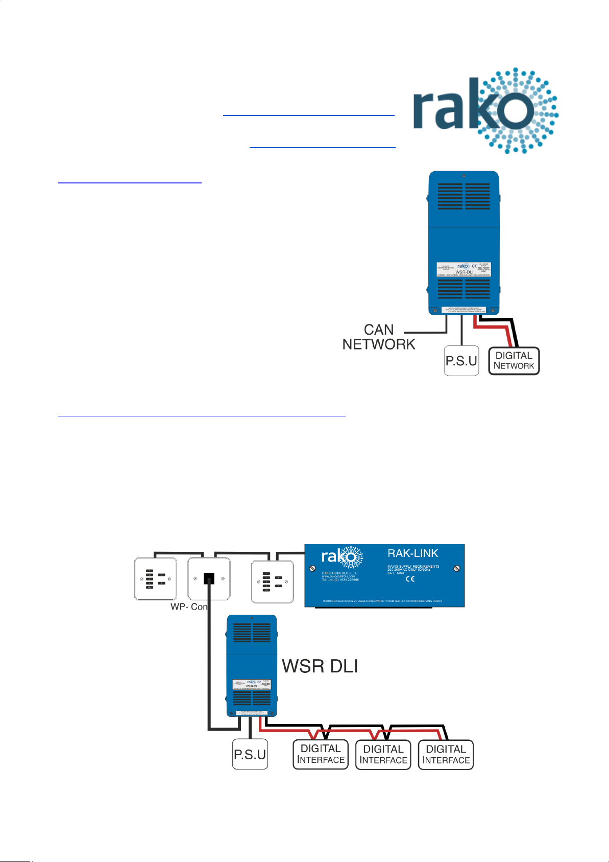
Connecting WSR-DLI to Rako Wired Network
The WSR-DLI can be connected to the Rako Wired Network in several ways. It has the option of
either a RJ11 cable connection or a 8 way Krone connector via the “Can connect” daughterboard
provided with the WSR-DLI.
RJ11 Cable connection options - RAK-LINK, RAK-STAR, WP-CONC, WP-CON.
The example below shows the WSR-DLI connected to the wired network via a WP-CON in a radial
configuration
WSR-DLI Manual Version 2.0.3
Page 2
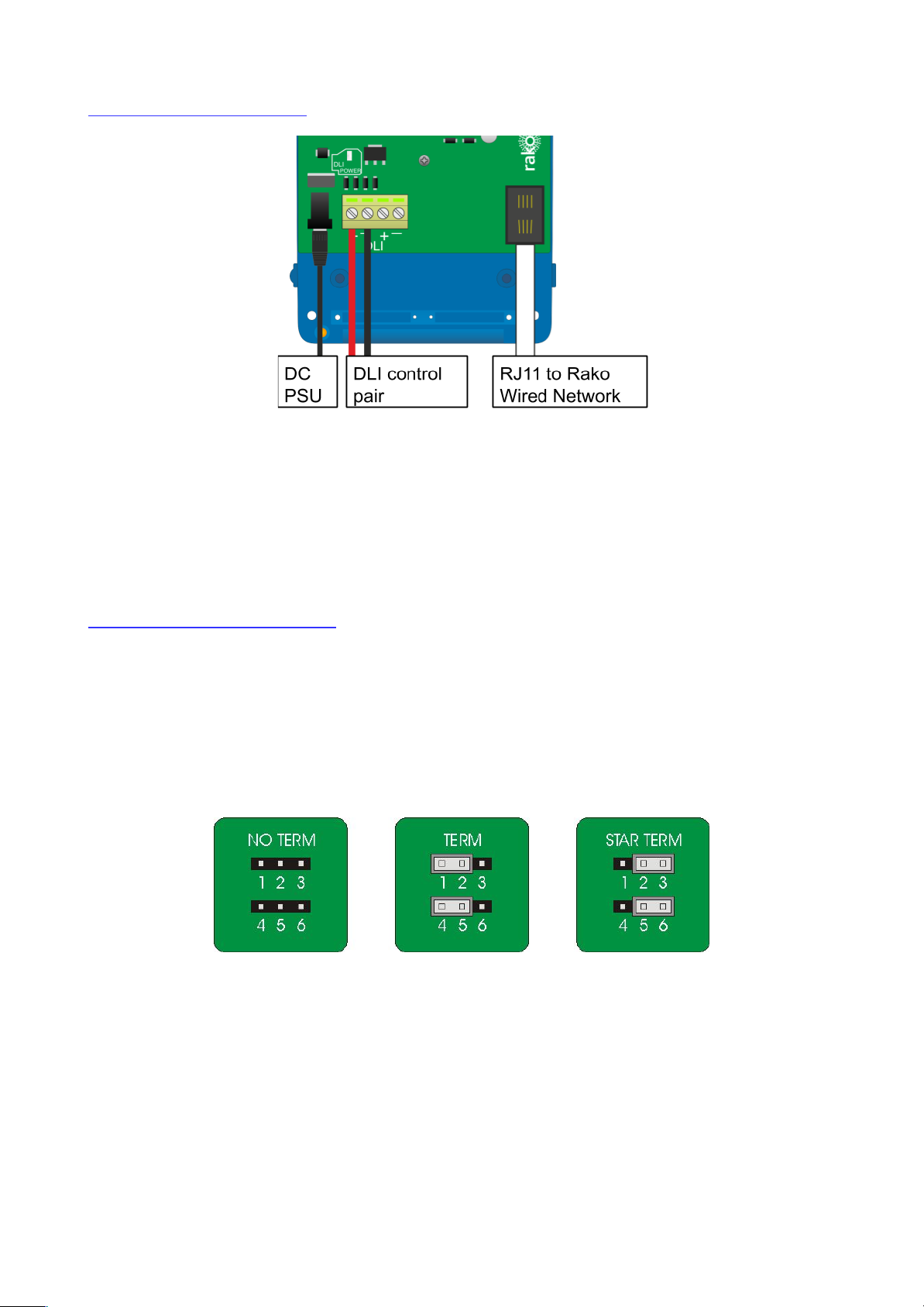
Installing the WSR-DLI
The WSR-DLI must be connected to the Rako wired system by the RJ11 port either plugged
directly to RAK-LINK or RAK-STAR or punched down to the CAT5 cable via a WP-CONC. The
WSR-DLI requires 18V DC, a suitable power supply attached to a 13A plug is provided with the
product. When successful powered up LED 2: the “Power LED” will illuminate.
NB - This power supply is to power the circuit board and DLI output of the WSR-DLI only. The power for the
fittings themselves is provided directly to the ballast, the output from the WSR-DLI is a control signal only.
Terminating the WSR-DLI
TERMINATION ON THE WSR-DLI ITSELF IS ONLY REQUIRED WHEN USING THE 8 WAY
KRONE CONNECTOR “CAN CONNECT” DAUGHTERBOARD.
The final step in the installation process is to terminate the WSR-DLI. The termination that is
required depends on the nature of the installation and the position of the WSR-DLI within the
system.
Termination Jumper settings:
No Term - Both Jumpers removed
Used when the WSR-DLI is not at the end of line. This is usually identifiable by two cables being
punched down to the WSR-DLI.
Term - Jumper fitted across 1+2 & 4+5
Used when the WSR-DLI is end of line in a daisy chain configuration.
Star Term - Jumper fitted across 2+3 & 5+6
Used when the WSR-DLI is end of line in a STAR wire configuration.
WSR-DLI Manual Version 2.0.3
Page 3

Adding the WSR-DLI as a device
For the WSR-DLI to operate correctly with a RAKO system
some initial setup must be performed. This is done using a PC
running RASOFT Pro (WSR-DLI is not supported by RASOFT
classic) and communicating with a RAKO Bridge or HUB
connected to the same wired system as the WSR-DLI .
Open the Project File for the installed Rako system and make
sure that Rasoft is connected to a communication device.
NB
The communication window at the bottom right should indicate whether a HUB/Bridge is connected or not.
For instructions on how to connect to a HUB/Bridge see Rasoft Pro programming guides and applicable
instruction manuals.
- Select “File” - “New device” to bring up the “New device Wizard” and choose “WSR-DLI” from the
list.
- Choose a suitable device name (if you have multiple WSR-DLIs make sure it is identifiable from
this description). Leave “Device ID” blank with the “Automatic ID” box checked.
- Associate the WSR-DLI to a room from the drop down menu. The room selected here will set the
“Local Room” for this device, leave “Associate to channel” blank.
- Once this screen appears press and hold the blue button on the WSR-DLI. After a few seconds it
will enter Setup Mode and the status LED will start to blink. Release the button and “Waiting for
device to enter setup” should change to “Device Found”.
- Click the “Finish” button to complete setup rako
The WSR-DLI is a multi-channel device and will occupy the entire room. By default Short Address
0 will be addressed to Channel 1 in the Rako Room, DLI Short Address 1 to Channel 2 and so on
for all 15 Channels.
WSR-DLI Manual Version 2.0.3
Page 4

Assigning the DLI short addresses
At this stage the WSR-DLI has been addressed and the Rako channels are associated to DLI short
addresses. However the ballasts themselves do not have DLI short addresses assigned to them.
To address the DLI ballasts open the “DLI Setup” tab in the WSR-DLI device editor (select the
RSR-DLI in the device list to open the device editor).
Force Readdress:
This will delete all current short addresses and replace them with an entirely new set. It is
advisable to use this button when initially addressing the DLI ballasts in a new system.
Automatically Readdress:
This button will assign DLI short addresses to any Ballast that is unaddressed. If additional ballasts
are added this will assign addresses to the new ballasts while leaving the previous addresses
unaffected.
Managing the WSR-DLI channels
To use the Circuits mapping page “Use group mapping” must be selected. When in “Use
Direct mapping” mode Rako channels will always be set as DLI short addresses -1 (DLI
short address 0 = Rako channel 1, DLI short address 1 = Rako channel 2 etc.) regardless of
how the mapping page appears.
Sometimes it may not be desirable to have the DLI channels arranged in the order they have been
auto-assigned using “Automatically Readdress” or “Force Readdress”. This is achieved using the
Circuits (Mapping) tab in “Use Grouped Mapping”.
When “Use Grouped Mapping” is selected the Rako channels become mapped to DLI groups. This
means that any number of DLI short addresses can be mapped to a single Rako channel and in
any order. This is useful if more than 15 DLI short addresses need to be assigned to a single
WSR-DLI or if the ballast(s) are not set to the desired Rako channel.
WSR-DLI Manual Version 2.0.3
Page 5

It is possible to test which ballast is associated to which short address by using the test column on
the mappings page. Double click on “test” to send and “on” to this ballast, double clicking again will
send an “off.” When an “on” is successfully sent the row will appear as below.
Shortcut commands exist for testing individual DLI short addresses, select the column of the short
address to be tested first
The <, key = Send on
The >. key = Send off
The ?/ key = Toggle on/off
Auto Heal Data
When programming is complete press this button to store DLI network information. Failure
to do so will mean in the event of lamp failure the entire DLI network will need to
re-programmed.
This button will store the current state of the DLI network within the WSR-DLI. This means that if a
single ballast is removed and replaced the new ballast will have the same short address
automatically uploaded to it. If more than one DLI ballast needs to be replaced the entire network
must be re-addressed using the “Force Readdress” button.
Advanced features of WSR-DLI
Swap Channels
The Swap Channels tile in the DLI setup tab allows for custom readdressing of the DLI short
addresses themselves. Individual short addresses can be moved on to or swapped with each other
by using this interface.
WSR-DLI Manual Version 2.0.3
Page 6

This will readdress the DLI ballast to the short address as set in each box, “Perform Swap” will
directly switch the position of the two ballast. “Perform Move” will result in both ballasts having a
the short address of “DLI Short Address 2”.
Visible Channels
Sometimes not all 15 channels in the room will be required by the WSR-DLI (less than 15
separately controllable sets of DLI ballasts required). When this is the case then the “Visible
Channels” tab can be used to reduce the number of channels the WSR-DLI occupies in the
software.
Slide the “channels used” slider to match the number of Channels required by the WSR-DLI and
the remaining channels are freed up to be used by other devices.
WSR-DLI Manual Version 2.0.3
 Loading...