

Page 1
WRB100 Instruction Manual
General
The WRB100 module is a repeater for use with either wired or wireless systems. Follow the
appropriate instructions according to the type of installation.
Installation
Before commencing installation of the Rako WRB100 modules, first read this instruction manual
carefully.
Do not install in direct sunlight.
Instal in a dry location with adequate ventilation
Rako Controls Ltd accepts no responsibility for any damage or injury caused by incorrect
installation of a Rako product.
Care and maintenance
General: Rako thanks you for having purchased a Rako product and hopes that you are pleased
with your system. Should for any reason you need to contact us please contact us via our
website www.rakocontrols.com or by phoning our customer help line on 01634 226666.
Page 2

Installation in a Wireless System
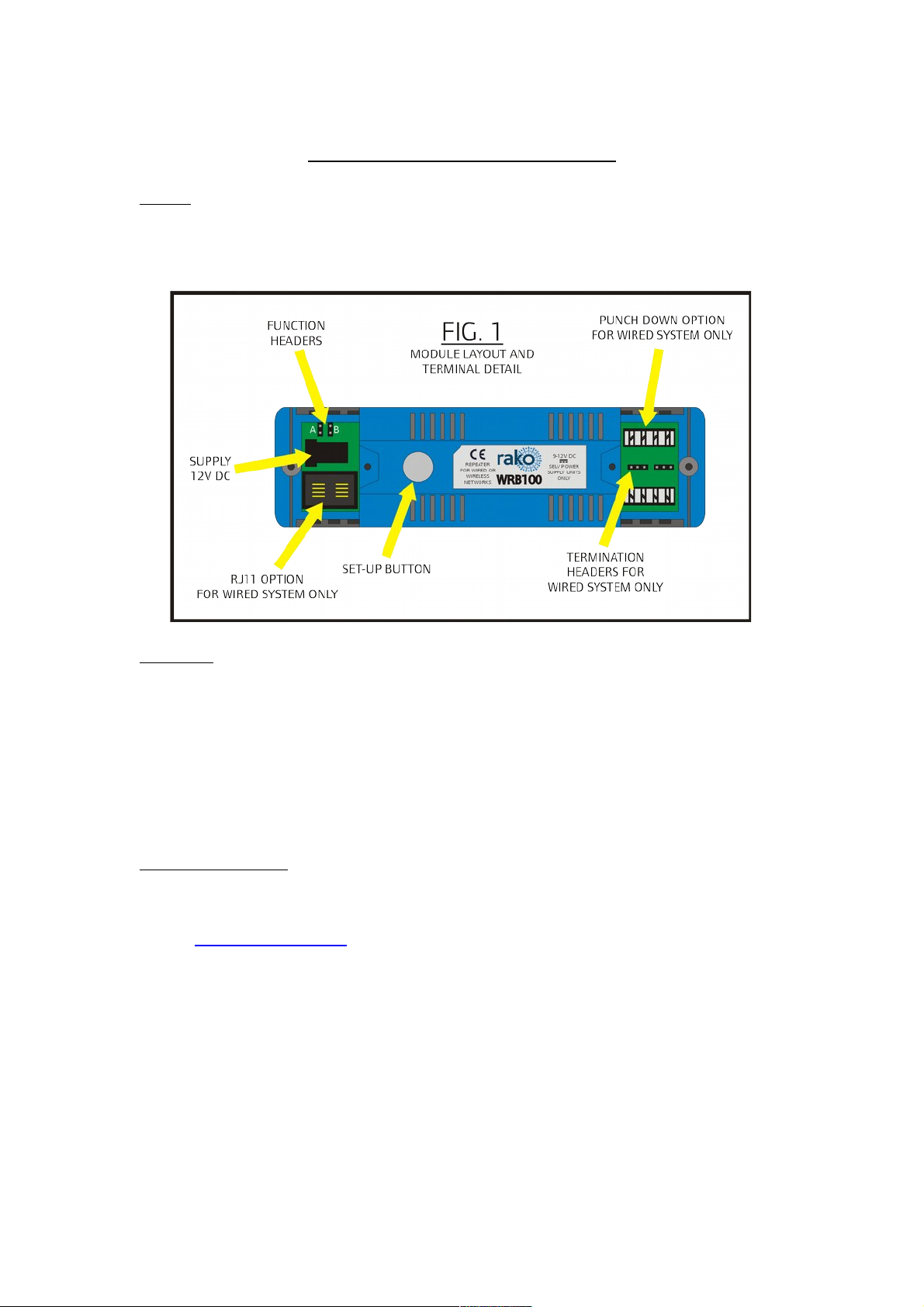
The WRB100 is supplied with a 12V DC power supply and an RJ11 connection lead. For wireless
systems the RJ11 lead is not required.
The 12V DC power supply should be plugged into a source of 230V mains power and the other
end connected to the concentric jack plug (see Fig 1 connection detail).
The WRB100 is fitted with other connectors and header connectors. These are not used in a
wireless installation.
Addressing
The module needs to be given an address, in the same way as other wireless modules in order to
function. Unlike other wireless modules the Room and Channel number is unimportant, but it is
essential that the module be given the same House address as other modules in the system. As
the unit will not receive an address without a definite Room and Channel number pick any
Room and Channel number. It is recommended, but not essential, that this is not the same
Room and Channel number used by any other modules.
Aerials.
As the purpose of a WRB100 module is to extend the wireless range of a system it is important
that the two aerials (receive and transmit) are kept straight and clear of any obstructing
materials (for radio signals this generally means metalwork).
Location
The purpose of a WRB100 module in a wireless system is to receive and re-transmit Rakom
wireless messages. To work effectively it needs to be positioned so that it is receiving range of
all the required transmitters and also in transmitting range of any required receivers. Normally
this means a mid-point between the two.
Checking Correct Operation
The WRB100 module has two internal LEDs below the set-up button, one blue and one red.
The blue LED flashes when the unit receives ANY Rakom command, the red LED flashes when
the unit transmits a message. In order for a WRB100 to repeat a message it must be set to the
correct House address (see above) therefore if the red LED flashes when a button is pressed
then the unit has been addressed and is functioning correctly.
Using Multiple WRB100 modules
To avoid the possibility of multiple modules getting locked into a transmitting 'loop', messages
from a WRB100 are 'flagged' as boosted messages and will not be re-transmitted by other
WRB100 modules. With programming and careful consideration it is possible to add further
WRB100 modules to a system. Contact Rako Controls technical helpline for further details.
Page 3

Installation in Wired Systems or a Wired 'Spine' for a Wireless Network
General
The Rako WRB100 module is designed to link between a Rako Wired system and a Rako
Wireless system. It will interface between the systems, passing signals between the two.
The WRB100 can also be used to form a ‘wired spine’ for a Rako Wireless network, where the
wireless system is installed over a widely spread area, or where there are physical obstacles that
prevent normal radio transmission. Such obstacles may include large concrete structures,
underground locations, metal barriers and so on. The WRB100 then works by using a wired
connection between the different locations. Any Rako radio signal in one area is fed down the
wire and then retransmitted by WRB100 modules in other locations. See figure 2.
Connections
The WRB100 can be connected to the CAT5 network using either the punch down connectors
(Fig 4 and Fig 5) or by using the RJ11 lead plugged into either a WP-Con or WP-ConC
connector (Fig. 6)or plugged directly into a RAKLink or RAKStar.
Function Headers
In order for the WRB100 correctly when connected to a wired network, or 'spine' arrangement
the header connector (see Fig. 1) should be fitted across the two pins marked 'A'.
Power Supply
If the WRB100 is connected to a CAT 5 network powered by a Rako RAK-Link then power is
taken directly from the system and no PSU is required. In wired networks such as a 'spine'
arrangement as shown in Fig. 2 + 4 each WRB100 requires an SELV 9V or 12v DC power supply.
The Rako power supply ref: RAPSU can be used or alternatively one of an equivalent
specification.
Addressing
The WRB100 needs to be given an address, in the same way as other system components in
order to function. Unlike other units the Room and Channel number is unimportant, but it is
essential that the module be given the same House address as the rest of the system. As the
unit will not receive an address without a definite Room and Channel number pick any Room
and Channel number. It is recommended, but not essential, that this is not the same Room and
Channel number used by any other devices. To assign an address press and hold the set-up
button until the internal LED flashes Blue, then release the button and sent an ident command
from either a wallpanel or the Rasoft programming software.
Terminations
When using the WRB100 as part of a wired, or wired 'spine' it is important that the termination
headers (see Fig.1) are set correctly. Any modules which are at the end of a daisy chain
connection should be set to the 'Term' position. Any modules which are at the end of a line
coming from a RAKStar should be set to 'Star' position and any other modules should be left as
unterminated. See Fig 7 for detail.
Your system should now be ready to operate.
Page 4

Figure 2
Figure 3
Example: 2 WRB100 used to create a Range Extending
Wired Spine in a Wireless system
Example: WRB100 used as interface between Wired &
Wireless systems
Page 5

PSU
+9 to +12V DC
WIRING UP THE WRB100 MODULES
WITH CAT 5 CABLE
PSU
+9 to +12V DC
CAT5 Network
Cables
PSU
+9 to +12V DC
PSU
+9 to +12V DC
Set Jumpers
to “Term”
Position in
modules at
each end of
Line
Fig. 4
Fig.4: WRB100 can be used as range boosters in a Wireless system.
Each WRB100 has it’s own power supply which is plugged to DC
connector. WRB100 has punch down connectors for CAT5 cable to
connect data from one WRB100 to another. At each end of the CAT5
line the WRB100 jumpers must be set to “Term”. The system is not
limited to 4 modules: More modules can be added as required to
create longer chains.
Fig. 5: WRB100 used to interface between Wired and Wireless
systems. The WRB100 are wired to the system using CAT5 cable like
any other Wired device. There are no power supplies as the WRB100
take their power from the wired system.
RAKLink Unterminated if it
is NOT at end of CAT5
cable
CAT5 Network
Cables
RAKLink Terminated if it IS at
end of CAT5 cable
Fig. 5
Page 6

Using RF-Bridge with RJ11 Connector and
WRB100
WRB100
WP-CON is alternative method for
installation.
Network terminations are in the WP-CON
and no termination resistors need be added to
the RF-Bridge.
Fig. 6
Figure 5
 Loading...