

Page 1
WRA-232 User Manual
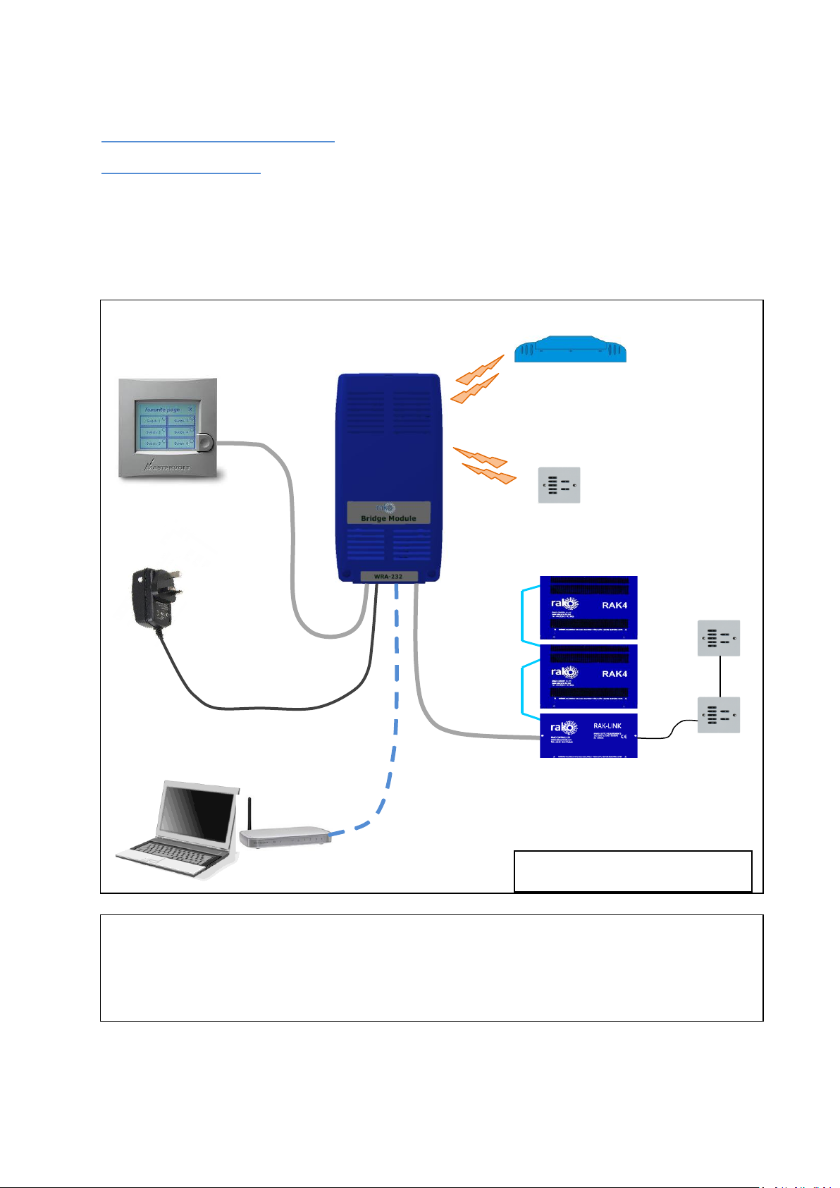
Send Wireless messages
to dimmers
Receive Wireless messages
from Wall plates
Send & receive
RS232 messages
Send & receive messages
from Rako Wired system
Power supply *
Power supply is not required if WRA-232 is
used with a Rako Wired system
*
Note:
WRA-232 will operate with Wired and Wireless systems. However, it cannot be used to link a Wired
System to a Wireless system. Use WA-Bridge or WTC-Bridge for that function.
What is WRA-232
WRA-232 will send and receive RS-232 messages with Rako systems.
WRA-232 works with Rako Wired or Wireless systems.
WRA-232 has Ethernet port for configuration only.
Page 2

Getting started with WRA-232
Use a laptop to connect
to the RTC-Bridge
The WRA-232 URL is
http://rako232bridge
Or
http://rako232bridge.local
Use a Web Browser to
view the WRA-232
control panel.
Some initial setup of WA-Bridge is needed.
First, Plug the Power Supply into the WRA-232 and apply power. The Blue LED on the WRA-
232 circuit board will start to blink.
Plug the Ethernet patch cable from the WA-Bridge to a spare port on a wireless router.
Use a normal web browser (eg Internet Explorer) to connect to the RTC-Bridge via the
router.
Page 3
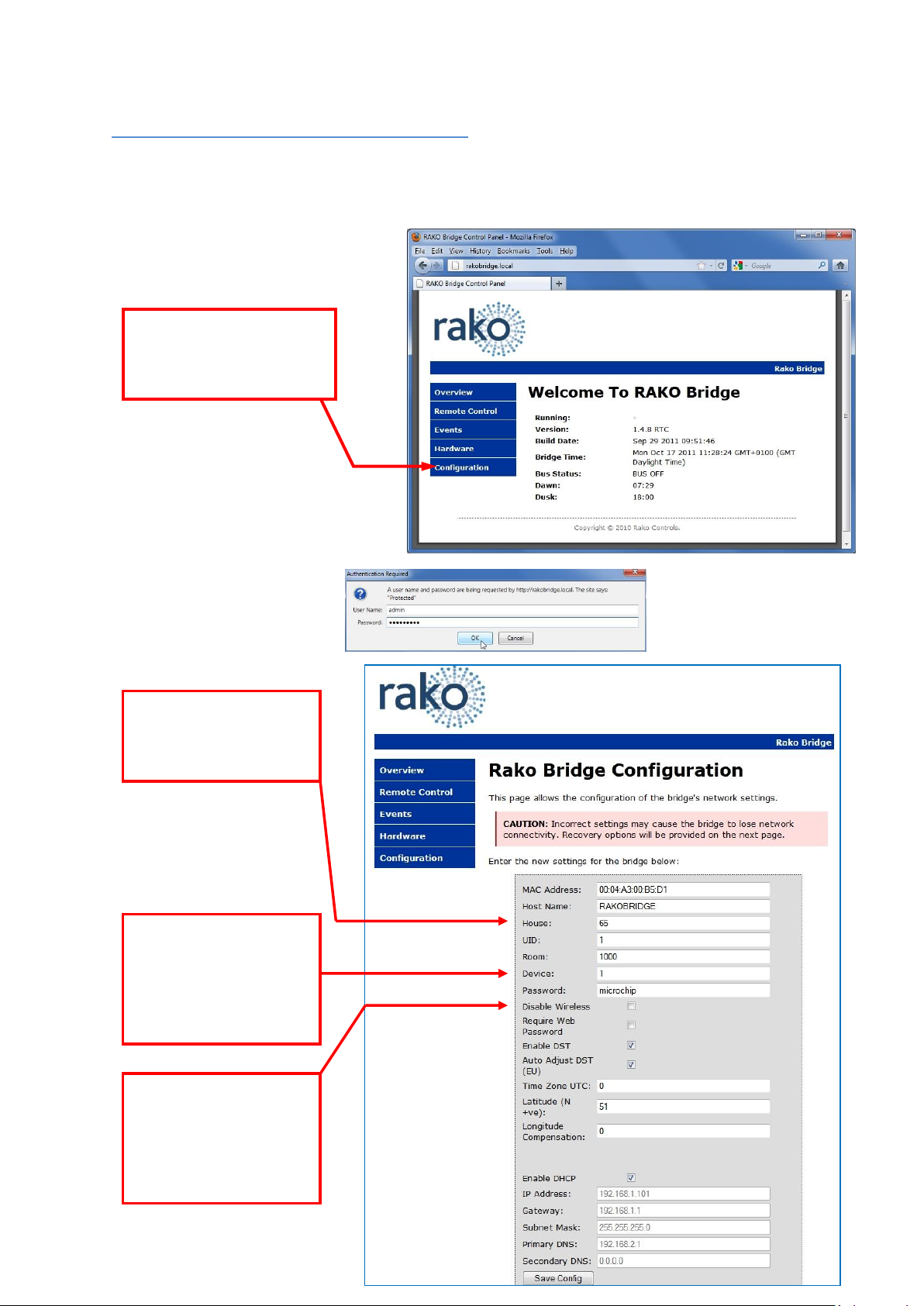
Basic Configuration of the WRA-232
Click the Configuration
button on the WRA-232
control panel.
Login
User Name = admin
Password = microchip
Set the House number
to match Rako Wireless
system
If the WRA-232 is used
on a Rako WIRED system
then change this Device
Number. See Notes on
next page
This option can be used
to Disable the Wireless
transmitter & receiver
on the WRA-232. See
notes on next page.
For WRA-232 to operate correctly with a RAKO system some initial setup must be performed. This is
done using a PC and the RJ45 configuration connector.
Set Wireless House Number
Page 4

WRA-232 Device Numbers
This setting is important when the WRA-232 is used with a Rako Wired system.
In the Wired system all Bridges, Wall Controllers, RAK-Links etc have unique identifiers. It is
important that no two items in the same logical Room have the same Device numbers.
The WRA-232 default room is Room 1000. This room number is also used by WRA-Bridges and WABridges. If there is a WA or WRA Bridge on the system then be sure that the WRA-232 and the other
Bridge have different device numbers.
Disabling the WRA-232 Wireless
Do not have two Bridges on the same system which both have Wireless enabled. This will cause
messages from one Bridge to be received by the other causing several repeats of the same message
to occur.
It is common for a WRA-232 to be in the same system as a RA-Bridge, RTC-Bridge, WA-Bridge or
WTC-Bridge. If this is the case, then disable the WRA-232 wireless.
Using WRA-232 with RS-232
The Rako WRA-232 uses the following configuration:
9600 baud, No Parity, 8 Data bits, 1 stop bit
The flow control should be set to Xon/Xoff or None.
Command Line Interface
The interface indicates it is waiting for a command by issuing the “>” character. Characters sent to
the interface are echoed. The interface interprets text commands and, where necessary, encodes
and transmits the appropriate message via the radio link. The interface is not case sensitive. Each
command consists of the following:
[COMMAND] <VALUE>
The command is terminated with a carriage-return character and, depending of the command, has
an additional argument. The argument is delimited by one or more white-spaces, tabs or colons. If
the Command is valid, the interface responds with:
OK
If the command is invalid, the interface responds with:
Invalid Command!
It is not necessary to enter the full text of the command. A shortened non-ambiguous version can
be used. For example the command HOUSE:1 can be shortened to HO:1.
Page 5

Command Summary
Command
Notes
ROOM [<room_number>]
Sets the ROOM address to <room_number>.
The Room number must be between 0 and 255.
Room 0 controls all units with the same House
address. If <room_number> is omitted, the room is
set to 0. The Room address is stored in non-volatile
memory.
CHANNEL [<Channel_Number>]
Selects the Channel address. The <channel_number>
must be between 0 and 15. Channel 0 controls all
channels within the current Room. If
<Channel_Number> is omitted the channel is set to 0.
SCENE <scene number>
Sets the scene for the current House/Room/Channel.
The <scene number> must be between 1 and 4, which
correspond to the buttons on a control panel.
OFF
Turns off the lights in the current
House/Room/Channel.
LEVEL <Power_level>
Sets the power level for the current
House/Room/Channel. The <power_level> must be
between 0 and 255, with 255 representing 100%
power.
STORE
Stores the current power level to the current Scene.
This will only apply to dimmers addressed by the
current House/Room/Channel.
RESET
Resets the microcontroller.
VER
Displays version information
STATUS
Displays current House, Room and Channel in the
form:
HO:nnn RO:nnn CH:nnn
nnn is 3 digit decimal number with leading zeros.
nnn is between 0 and 255.
Page 6

Command
Notes
COMMAND [<command_number>]
Issues <command_number> to the lights in the
current House/Room/Channel. The
<command_number> must be between 0 and 15.
ADDRESS <EEPROM_address>
Sets the EEPROM address within the dimmers. The
(EEPROM_address> must be between 0 and 127.
DATA <EEPROM_data>
Transmits <EEPROM_data> to the address set using
the ADDRESS command. The <EEPROM_data> must
be between 0 and 255.
NOECHO
Turns off character echoing. This command is only
available on the Bi-directional RS232 interface. The
current echo mode is stored in non-volatile memory.
ECHO
Turns on character echoing. This command is only
available on the Bi-directional RS232 interface. The
current echo mode is stored in non-volatile memory.
Table 1 – Command Line Interface
Page 7

Command Number Summary
Instruction
Number
Instruction
Program
mode
instruction
0
off
1
light+
light+
2
light-
light-
3
ps1
Store + Ident
4
ps2
ch+
5
ps3
ch- 6 ps4
7
program mode
8 ident
ident
9
10
low battery
low battery
11
eeprom write
eeprom write
12
level set
level set
13
store
Store
14 exit
15
STOP
STOP
Using the COMMAND instruction, a literal command can be sent to the addressed controllers. Table
2 details the meanings of the various instructions.
Table 2- Command Instructions
To fade the lights the command light+ or light- must be issued. This fades the lights at the rate
determined by the value stored within the dimmer. To stop the lights fading the STOP command
needs to be issued.
EEPROM Addresses
Information is stored in the dimmers in non-volatile or EEPROM memory. This memory can be
written to using the RS232 interface. The EEPROM consists of 128 bytes of storage, some of which is
used internally by the dimmer to remember the current state. ONLY THE ADDRESSES DETAILED
BELOW SHOULD BE WRITTEN TO. To write data to the EEPROM area it if first necessary to set the
Page 8

HOUSE,ROOM and CHANNEL address of the dimmer(s). Next, the address should be set using the
EEPROM
ADDRESS
Action
Notes
1
Scene 1 preset value
2 Scene 2 preset value
3 Scene 3 preset value
4 Scene 4 preset value
9
Start Mode (After power
failure)
0=0ff
1-4 = Scene
5=Memory
6-255=Absolute power level
22
Ignore Program Mode
>0= Ignore
23
Ignore Group Commands
>0 = Ignore
24
Ignore House Commands
>0 = Ignore
26
Use Profile
>0 = use profile
34
Scene Fade Rate
0=fast
36
Scene Fade Decay Rate
0=no decay
40
Manual Fade Rate Max
Sets the maximum rate
48
Manual Fade Rate
Acceleration
Sets the acceleration to maximum rate
50
Manual Fade Rate Start
Sets the starting fade rate
63-127
Profile Data
Determines the dimmers profile
These values should only be changed using the
RASOFT software.
ADDRESS command and finally, the data should be written using the DATA command.
Care should be taken when changing values if the channel or room number is set to zero as this will
change the values on all the dimmers.
Table 3- EEPROM Addresses
Page 9

Bi-Directional operation
The Rako® Bi-directional RS232 interface works as both a transmitter and receiver of Rako coded
messages. Using this module it is possible to interface a Rako lighting installation to an external
system where the system can both control the lighting and be aware of buttons being pressed on
Rako devices.
In addition to accepting the commands defined in Table 1, the Rako® Bi-directional RS232 interface
will output received commands in the following format:
<RRR:CC:IN
Where RRR represents the decimal room number from 0-255, CC indicates the channel number 0-15
(0 being ‘all channels’) and IN indicates the instruction as set out in Table 2- Command Instructions.
The string will always be on a separate line, start with a “<” and terminate with a CR LF.
The unit will only output messages for the current house. The house address must first be set using
as described in the “Table 1Basic Configuration” section.
The following sequence represents a controller in room 4. Note: the text in italics is for explanation
and does not appear on the output.
<004:00:03 Scene 1 button pressed.
>
<004:00:10 Battery low indication.
>
<004:00:01 Fade up button pressed.
>
<004:00:15 Fade up button released.
>
<004:00:10 Battery low indication.
>
Page 10

Command Examples:
This section details some typical command line examples. The ‘>’ character is issued by the interface
as is the ‘OK’ response. Note that the commands are not case sensitive, shortened versions of the
commands and various delimiters can be used.
The house and room address are stored in EEPROM within the WRA-232 and do not require
resetting should a power failure occur.
To set the dimmers in room 4 to scene 1
>RO:4
OK
>CH:0
OK
>SC:1
OK
For all the dimmers in room4, set the Start-Mode such that the lights will be at
50% following a power failure.
>ro 4
OK
>ch 0
OK
ADD 9
OK
Dat 127
OK
 Loading...