

Page 1
WK-EOS-6 Instruction Manual
For programming information: Wireless Module Programming Guide /
Wireless RAK Programming guide
For general overview: Wireless Module Application Sheet /
Wireless RAK Application Sheet
What is the WK-EOS-6?
The WK-EOS-6 is a six button keypad for use with Rako wired
systems. It will transmit Scene 1-3, Off, Fade Up/Fade Down in a
single room before any custom programming is added.
WK-EOS-6 require a RAK-LINK to operate as part of the system.
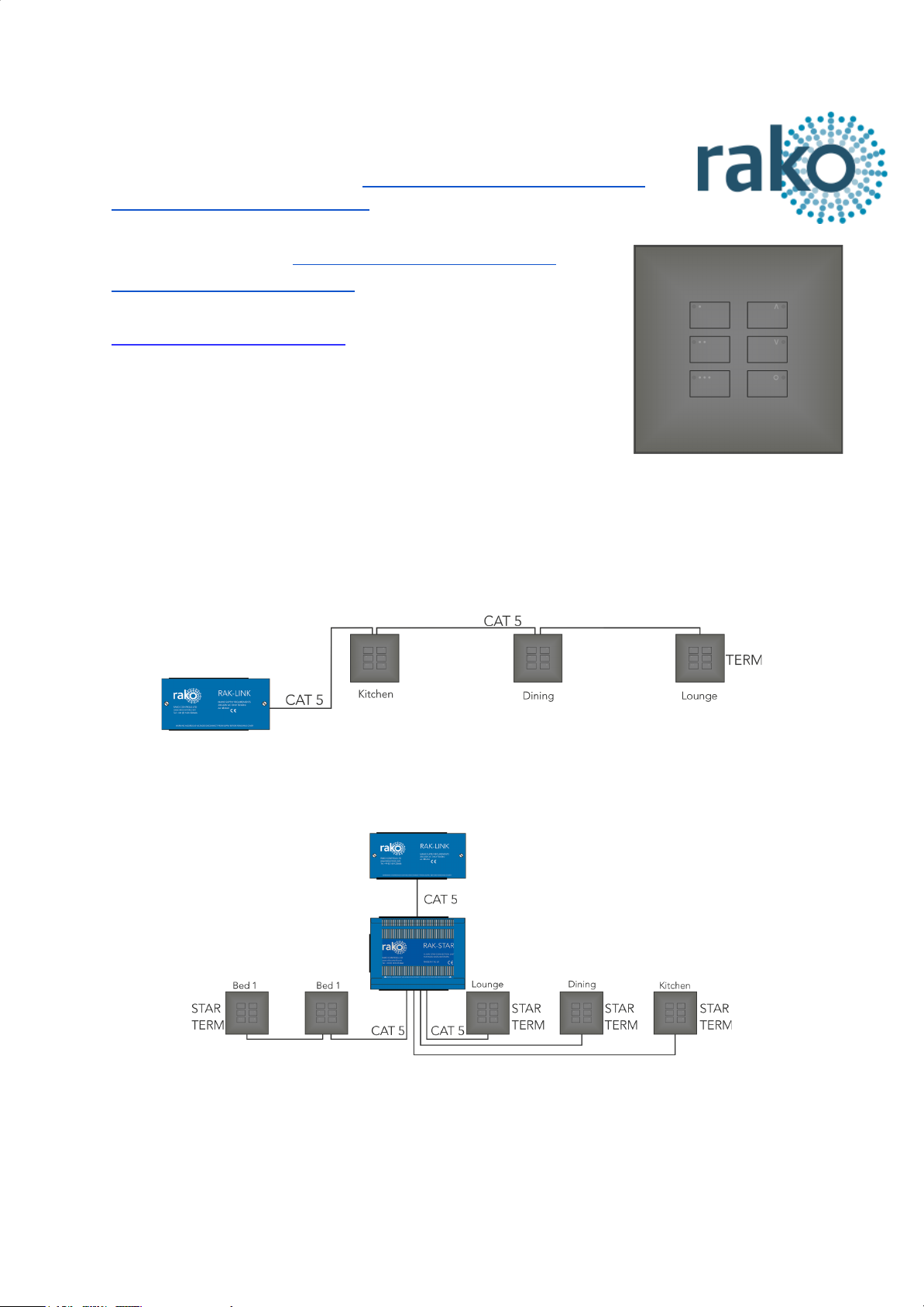
WK-EOS-6 (as part of the wired network generally) can be wired in two ways:
“Daisy Chain” configuration - A single run of keypads runs from the RAK-LINK and to an
end point. It is still usually advisable to run a return leg back to the RAK-LINK as a spare.
“STAR” configuration - Cables are all run back to a central point: a RAK-STAR usually
located with the RAK-LINK. Each cable can be from a single keypad or a leg of keypads.
Installation Note:
The WK-EOS-6 comes in two sections “Front” and “Back” they are referred to as such in the following
installation guide. The “Back” section is just a connection board for the CAT5/6 cable. The “Front”
section contains all memory and programming.
WK-EOS-6 Manual Version 1.0.1
Page 2
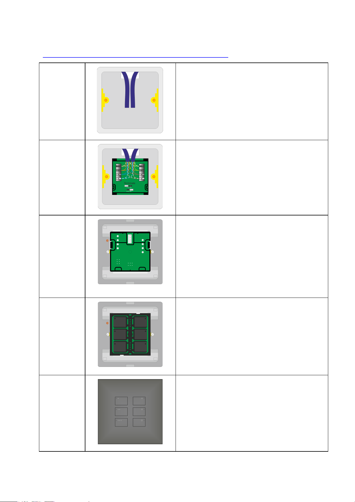
Installation of the WK-EOS-6 with WP-EOS-60-xx:
Step 1
Prepare cable(s) in backbox ready for connection.
Separate the two halves of the WK-EOS-6 ready
for installation. The “back” section (with the
punchdown connections) will be installed first.
TIP:
Leave plenty of slack if possible to allow for
re-punching down at a later date if required.
Step 2
Punch down cable(s) matching cable colours to
colours written on the circuit board.
There may be either one or two sets of cables to
punch down.
Step 3
Terminate the WK-EOS-6 as required. See
“Terminating the WK-EOS-6” on page 3 of this manual.
The back section of the WK-EOS-6 is now
installed and is ready for the front section and
cover plate.
TIP:
Take care when preparing and installing to not disturb
the punchdown connections. Loops are provided on
the back section to cable tie the cable(s) if desired.
Step 4
Clip the front section of the WK-EOS-6 into the
grid and connect the front section of the
WK-EOS-6 to the back section of the WK-EOS-6.
Screw the grid for the screwless cover plate into
the backbox.
TIP:
If the wired network is powered then the backlit LEDs
on the keypad will illuminate.
Step 5
Clip the cover plate into the grid to complete
installation.
WK-EOS-6 Manual Version 1.0.1
Page 3

Coverplates (WP-EOS-60-xx)
To mount the WK-EOS-6 to the wall a WP-EOS-60-xx is required as shown above. This is
available in a variety of finishes including:
- Satin Chrome (Silk) - WP-EOS-60-SC
- Polished Chrome - WP-EOS-60-PC
- Antique Brass WP-EOS-60-AB
- Matt Black - WP-EOS-60-MB
- Polished Brass - WP-EOS-60-PB
- Matt Bronze - WP-EOS-60-BM
- White (Matt) - WP-EOS-60-WH
Terminating the WK-EOS-6
It is important to terminate WK-EOS-6 correctly otherwise the wired
system will not function. The termination that is required depends
on the nature of the installation and the position of the RAK-LINK
within the system.
No Term - Both Jumpers removed
Used when the WK-EOS-6 is not at the end of line. This is usually
identifiable by two cables being punched down to the WK-EOS-6.
Term - Jumper fitted across 1+2 & 4+5
Used when the WK-EOS-6 is end of line in a daisy chain
configuration. For example the WK-EOS-6 marked “TERM” shown
in “Typical Wired Installation layout” on page one.
Star Term - Jumper fitted across 2+3 & 5+6
Used when the WK-EOS-6 is end of line in a STAR wire
configuration. For example the WK-EOS-6 marked “STAR TERM”
on page one.
Programming the WK-EOS-6
The WK-EOS-6 is programmed using the Rasoft Pro programming software. A
WA/WTC-Bridge or WK-HUB is required for any programming of a wired system.
Wired system Programming Guide - For information on how to programme the wired system
using Rasoft Pro.
WK-EOS-6 Manual Version 1.0.1
 Loading...