

Page 1
WCM-070 Instruction Manual
For programming information: Wired system Programming Guide
For general overview: Wired RAK Application Sheet
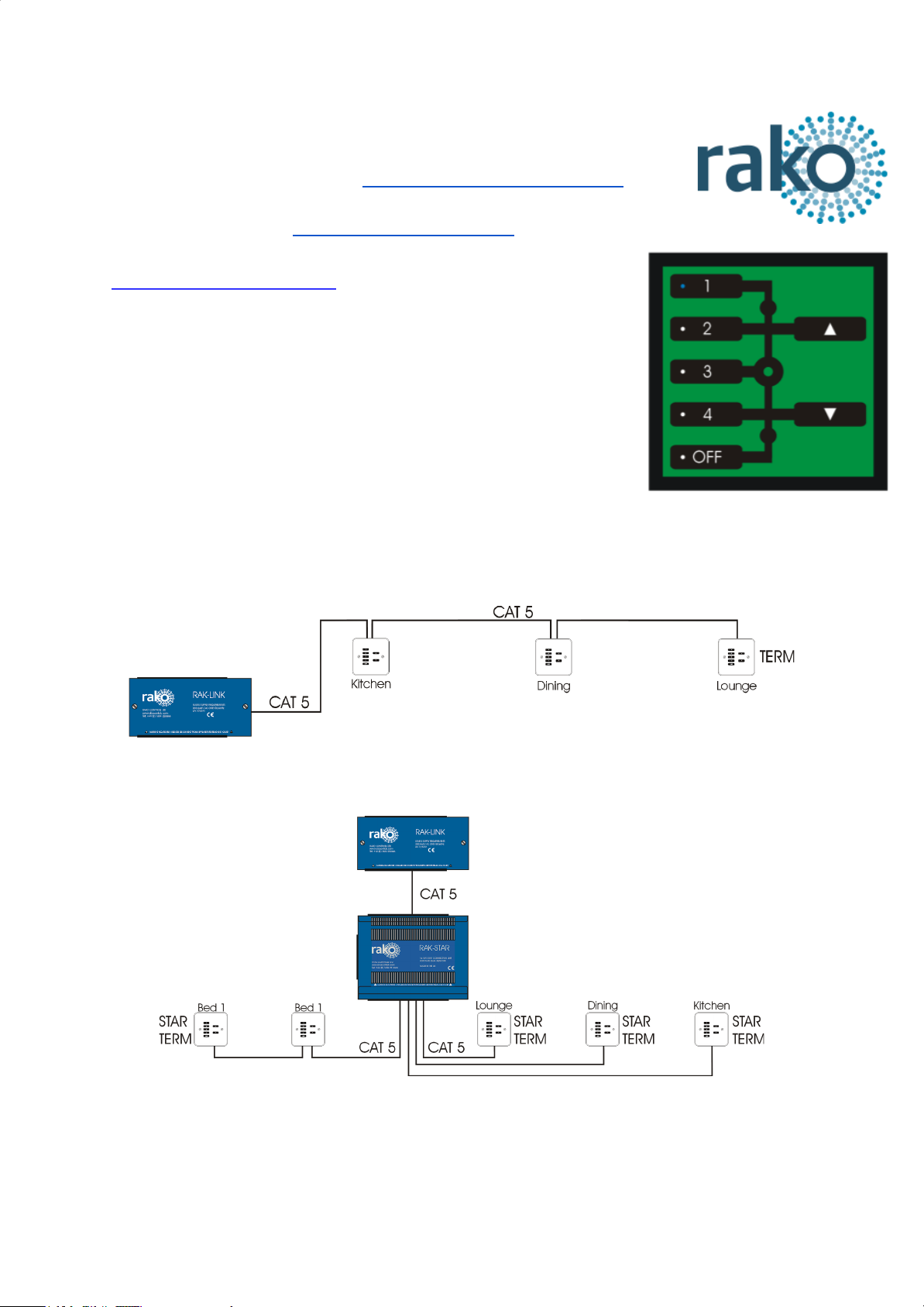
What is the WCM-070?
The WCM-070 wired keypad is a seven button keypad for use with
the wired system. It will transmit Scene 1-7, Off, Fade Up/Fade Down
in a single room before any custom programming is added.
WCMs require a RAK-LINK to operate as part of the system.
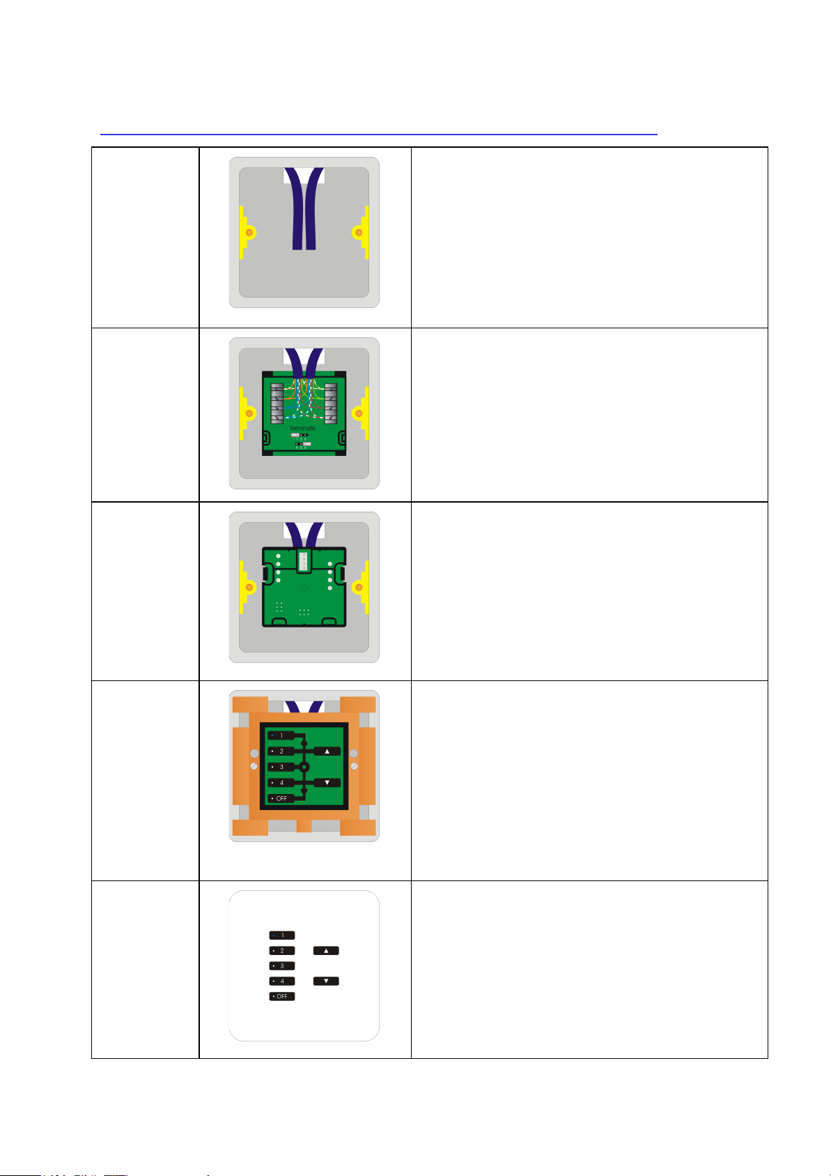
WCMs (as part of the wired network generally) can be wired in two
ways:
“Daisy Chain” configuration - A single run of keypads runs from the RAK-LINK and to an
end point. It is still usually advisable to run a return leg back to
the RAK-LINK as a spare.
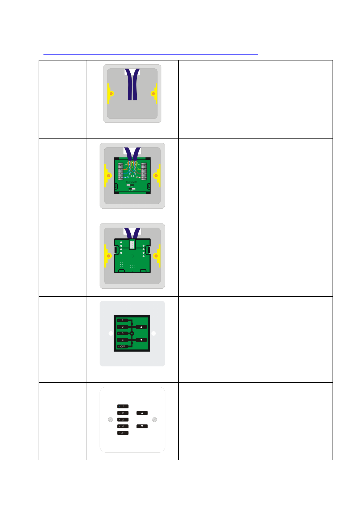
“STAR” configuration - Cables are all run back to a central point: a RAK-STAR usually
located with the RAK-LINK. Each cable can be from a single keypad or a leg of keypads.
Installation Note:
The WCM comes in two sections “Front” and “Back” they are referred to as such in the following
installation guide. The “Back” section is just a connection board for the CAT5/6 cable. The “Front”
section contains all memory and programming.
WCM-070 Manual Version 2.0.5
Page 2
Installation of the WCM with screwless finish plates (WLF/WLM):
Step 1
Prepare cable(s) in backbox ready for connection.
Separate the two halves of the WCM ready for
installation. The “back” section (with the
punchdown connections) will be installed first.
TIP:
Leave plenty of slack if possible to allow for
re-punching down at a later date if required.
Step 2
Punch down cable(s) matching cable colours to
colours written on the circuit board. There may be
either one or two sets of cables to punch down.
Step 3
Terminate the WCM as required. See
“Terminating the WCM” on page 4 of this manual.
The back section of the WCM is now installed and
is ready for the front section and cover plate.
TIP:
Take care when preparing and installing not to disturb
the punchdown connections. Loops are provided on
the back section to cable tie the cable(s) if desired.
Step 4
Clip the front section of the WCM into the grid and
connect the front section of the WCM to the back
section of the WCM.
Screw the grid for the screwless cover plate into
the backbox.
TIP:
If the wired network is powered then the backlit LEDs
on the keypad will illuminate.
Step 5
Clip the cover plate into the grid to complete
installation.
WCM-070 Manual Version 2.0.5
Page 3
Installation of the WCM with screwed finish plates (WVF):
Step 1
Prepare cable(s) in backbox ready for connection.
Seperate the two halves of the WCM ready for
installation. The “back” section (with the
punchdown connections) will be installed first.
TIP:
Leave plenty of slack if possible to allow for
re-punching down at a later date if required.
Step 2
Punch down cable(s) matching cable colours to
colours written on the circuit board. There may be
either one or two sets of cables to punch down.
Terminate the WCM as required. See
“Terminating the WCM” on page 4 of this manual.
Step 3
The back section of the WCM is now installed and
is ready for the front section and cover plate.
TIP:
Take care when preparing and installing not to disturb
the punch down connections. Loops are provided on
the back section to cable tie the cable(s) if desired.
Step 4
Clip the transparent surrounding mounting plate
and the WCM front board together.
Fit the WCM front board and attached surround to
the WCM back board.
TIP:
If the wired network is powered then the backlit LEDs
on the keypad should illuminate once the two halves
are connected together.
Step 5
Finally screw the cover plate into the back box
through the screw holes in the transparent
surround.
Installation of the WCM is now complete.
WCM-070 Manual Version 2.0.5
Page 4
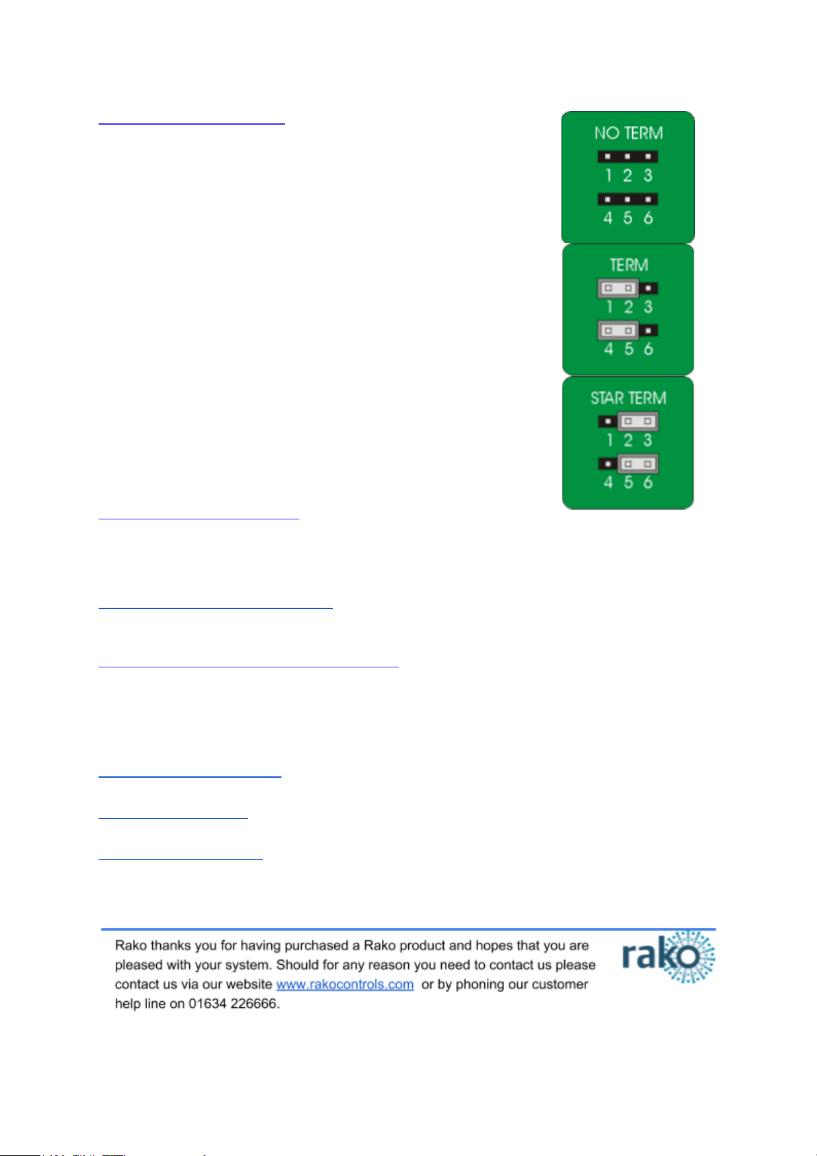
Terminating the WCM
It is important to terminate WCMs correctly otherwise the wired
system will not function. The termination that is required depends
on the nature of the installation and the position of the RAK-LINK
within the system.
No Term - Both Jumpers removed
Used when the WCM is not at the end of line. This is usually
identifiable by two cables being punched down to the WCM.
Term - Jumper fitted across 1+2 & 4+5
Used when the WCM is end of line in a daisy chain configuration.
For example the WCM marked “TERM” shown in “Typical Wired
Installation layout” on page one.
Star Term - Jumper fitted across 2+3 & 5+6
Used when the WCM is end of line in a STAR wire configuration.
For the example the WCMs marked “STAR TERM” on page one.
Programming the WCM
The WCM is programmed using the Rasoft Pro programming software. A WA/WTC-Bridge
or WK-HUB is required for any programming of a wired system.
Wired system Programming Guide - For information on how to programme the wired system
using Rasoft Pro.
Troubleshooting the Wired Network
Sometimes cabling problems or incorrectly punched down cables means a degree of fault
finding needs to be done on the wired network. The WCMs use backlit LEDs to provide fault
codes and this can be used in combination with the guides below to resolve problems.
WCM Diagnostic Feedback - For fault finding “Daisy Chain” and “Star” configuration.
RAK-LINK diagnostics - For fault finding “Daisy Chain” and “Star” configuration.
RAK-STAR diagnostics - For fault finding “Star” configuration.
WCM-070 Manual Version 2.0.5
 Loading...