

Page 1
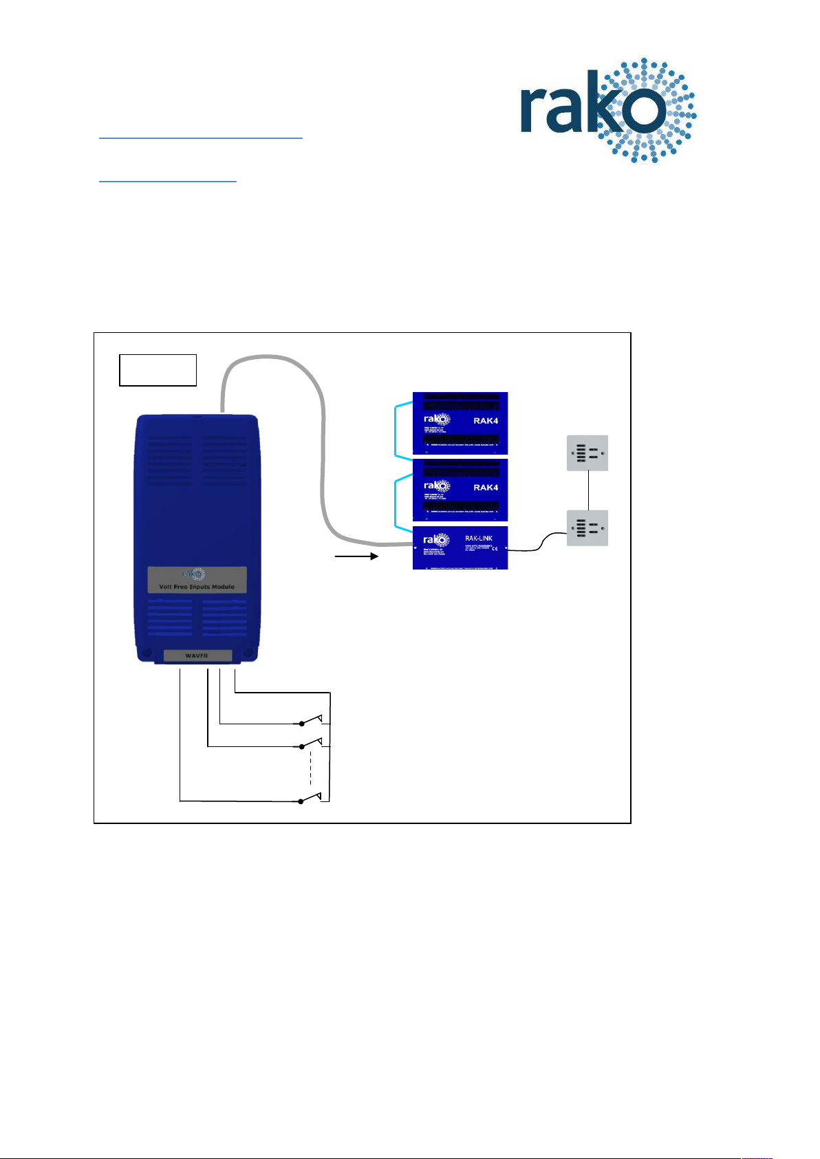
Send Commands to
Rako Wired system
Up to Ten Volt
free switches or
Logic Level Inputs
Figure 1
WAVFR User Manual
What is WAVFR
WAVFR allows mechanical switches and logic levels to add additional control of a Rako Wired
system.
This includes inputs from Alarm sensors, PIR modules, Thermo sensors, Light detectors. In fact
anything that can provide an electrical contact or a DC logic output.
Issue A Nov 2011 Page 1 of 5
Page 2
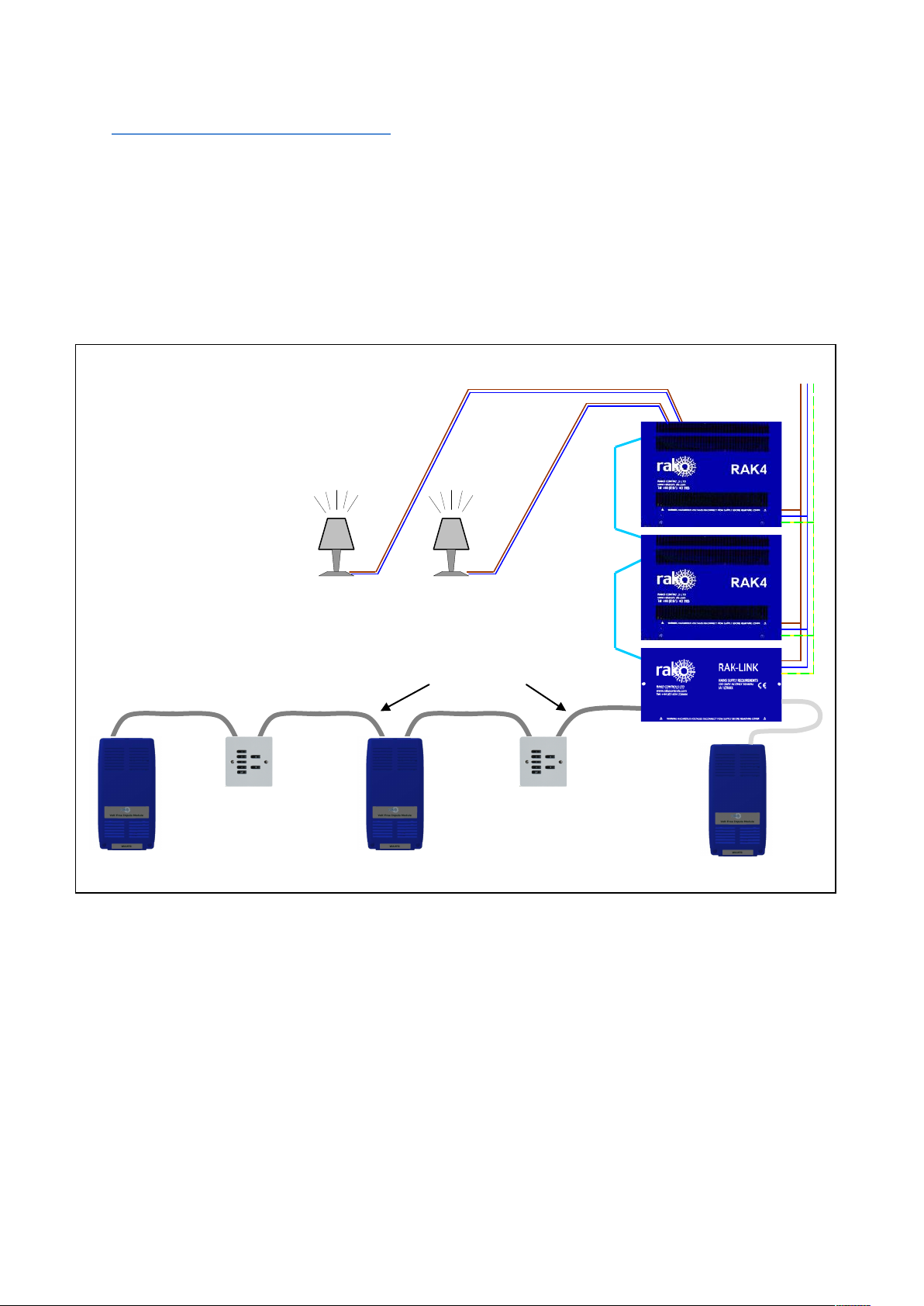
WAVFR 1
Wallplate1
WAVFR 2
Wallplate 2
RAKLink
A WIRED INSTALLATION
INCLUDING WAVFR MODULES.
Figure 2
230v ac
Cat5 data cable
Internal
RJ45 RAK4 cables
Lighting Circuits
WAVFR 3
Getting started with WAVFR
Connect WAVFR to system
WAVFR must be connected to A RAKO Wired System. The simplest method is by connecting the RJ11
patch lead from the WAVFR to one of the RJ11 sockets on a system RAK-Link or RAK-Star. The RJ11
patch lead may also be plugged into a WA-Con access point.
If the WAVFR cannot be mounted near to a RAK-Link etc then the connection may be made by CAT5
cable to the Punch Down Daughterboard. The normal rules apply for terminations when connecting
the CAT5 cable in this way, as on a Wired Wallplate.
In Figure 2 above:
WAVFR 1 is connected using Punch Down Daughterboard. It is at the end of the CAT5 cable so the
Term Jumper is set on its daughterboard.
WAVFR 2 is connected using Punch Down Daughterboard. It is in middle of the CAT5 cable so No
jumpers are set on its daughterboard.
WAVFR 3 is connected directly to a RAK-Link using RJ11 Patch Lead. The Daughterboard is unused
and No jumpers should be set on that daughterboard.
Issue A Nov 2011 Page 2 of 5
Page 3

Connect each remote input to one
of the terminals A-J.
Connect a return/ground wire
from each remote input to one of
the COM terminals
CAT5 Cable to Rako Wired system
RJ11 socket for direct connection
to a RAK-Link, RAK-Star or WP-Con
Inputs Indicator LED’s
Volt Free/Logic Inputs
Punch Down Daughterboard
Pushbutton Setup Switch
Figure 3
Apply Power to the system
The WAVFR takes its power from the RAKO wireless network. No other power supply is required.
Connect WAVFR by CAT5, or RJ11 to the wired system and power up.
Two LEDs will light on the WAVFR circuit board. The “Power” LED next to the RJ11 indicates that
correct volts are being received from the system. The LED “D25” near the terminal blocks shows that
the WAVFR on-board supplies are healthy.
Configure the WAVFR using RASOFT
For WAVFR to operate correctly with a RAKO system some initial setup must be performed. This is
done using a PC running RASOFT software and communicating with the Wired System via a RAKO
Bridge Product (WRE-Bridge, WA-Bridge of WTC-Bridge).
Open the Project File for the installed Rako system. Make sure that Rasoft is talking to the system
through a Bridge – Do not try to use RAUSB, RAH-Smart, RAV232 to make the connection. (Refer to
the Bridge User Instructions or the Wired System Programming Guide for assistance).
Press and Hold the WAVFR Setup Switch. After a few seconds the WAVFR will enter Setup Mode
and LED’s A,B,C,D,E on the WAVFR will start to blink.
Issue A Nov 2011 Page 3 of 5
A Message will pop up in Rasoft to acknowledge
that the WAVFR is in Setup Mode.
Press the Yes button to continue.
Page 4

Wired Volt Free Setup screen will be shown:
Add the WAVFR to the system. Give the
WAVFR a room number and name. Then press
Add button followed by Quit
The room number itself is not too important. Much more
important is that the WAVFR has its own unique identity.
It must not exist with the same Device Number as a
different device (WallPlate, RakLink etc) that is in the
same logical room. The Advanced Options check box will
allow manual setting of Device Number if this is proving
to be a problem
Press Update List Button to make the new WAVFR appear on list at bottom LH Corner. (The Default
WAVFR can be deleted from the list).
The new WAVFR should now appear as On-line. If it does
not, try Updating the List again, or even closing &
reopening this setup screen (Under Controls-Wired-
WAVFR tab)
Issue A Nov 2011 Page 4 of 5
Page 5

Input Enable Buttons
The current Map
being Edited
Program the WAVFR functions
The WAVFR is programmed in a similar way to a Rako Wired Wallplate.
The edit screen includes Input Enable buttons. Press in the buttons that correspond to WAVFR
inputs that have switches or logic inputs connected. Leave the buttons for any unused inputs
unpressed. Compare the Input Enable buttons on this screen with figure 3. In each case only inputs
A,B,C are in use.
Each Map has a Source and Action.
In this example the Source is that Input A is Made (Logic Low) for any time greater than zero
seconds. Each of the Source Buttons has a check box. This is used to set which inputs are used to
determine when this particular Map get triggered.
The Action for this map is that a Room 6, Scene 1 command is sent.
Other Maps will have different (or the same) source and will send appropriate commands.
________________________________________________________________________________
Technical Support
For more information contact Rako Controls Ltd 01634 226666 www.rakocontrols.com
Issue A Nov 2011 Page 5 of 5
 Loading...