

Page 1
RTC-Bridge User Manual
For an overview of Bridges: "Bridge Application Sheet"
For programming a wireless system: “Wireless Module Programming
Guide”/”Wireless RAK Programming guide”
Contents:
1 Functions of the RTC-Bridge
2 Installing the RTC-Bridge
3 Discovering the Bridge and Setting the House Number
3.1 Discovering the Bridge
3.2 To set the Bridge House number
3.3 If you cannot connect to the Bridge
4 Adding the Bridge as a device
5 Uploading the project file
6 Downloading the project file
7 Events
7.1 Setting Events using Rasoft Pro
7.2 Setting Events using the Rako App.
8 Mappings
8.1 Mapping wireless commands to give multi-room functionality
8.2 Triggering Macros from Maps
9 Macros
9.1 Writing Macros
9.2 Triggering Macros
10 Holiday Mode
11 UDP Feedback
11.1 Live feedback
11.2 UDP feedback log
12 Performing a Firmware upgrade
1 Functions of the RTC-Bridge
RTC-Bridge will add the following features to a RAKO wireless system:
- Network interface: including remote control via mobile devices.
- Storing Project file information: Room, Channel and Scene information can be
stored.
- Timed Events: Automatic functions at fixed times including dawn & dusk times.
- Mapping: Commands can be redirected to perform other tasks.
Page 2
2
- Macros. Series of commands that are triggered by a single command or event.
Specific steps can be enabled and disabled giving conditional functionality.
- Holiday Mode. Replays recorded scene activity, creating an occupied look to a
property.
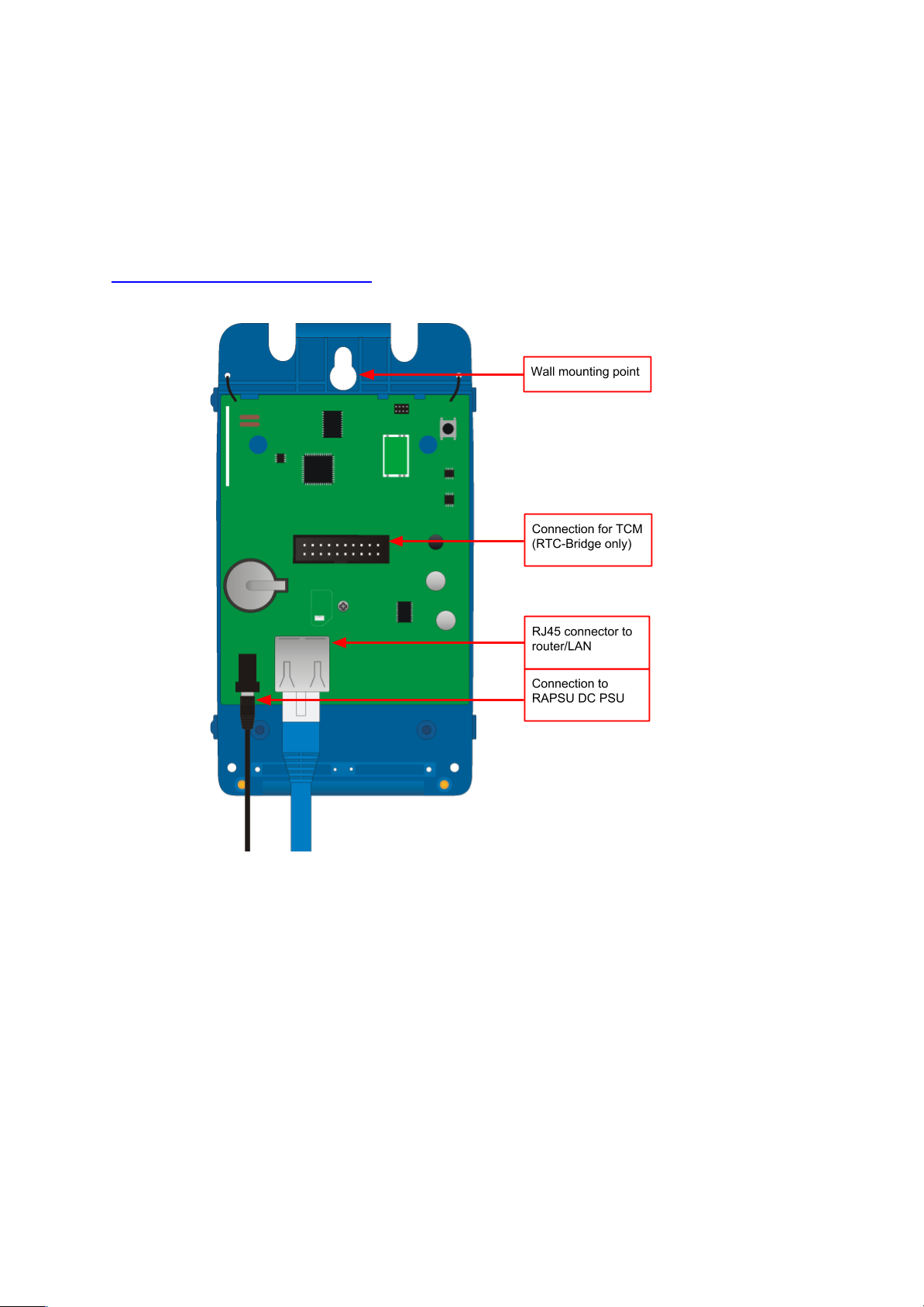
2 Installing the RTC-Bridge
- Step 1: Loosen the two screws and the bottom of the casing and remove lid.
- Step 2: Plug the power supply provided into the RTC-Bridge and an available 13A
socket.
- Step 3: Plug the Ethernet patch cable from the RTC-Bridge to a spare port in a router
or network switch.
- Step 4: Mount the Bridge to a wall using fixing point at top of case if desired.
- Step 5: Replace lid to complete installation.
RTC-Bridge Manual Version 2.1.4
Page 3
3
3 Discovering the Bridge and Setting the House Number
Before proceeding with any programming the Bridge needs to be discovered and the House
number set.
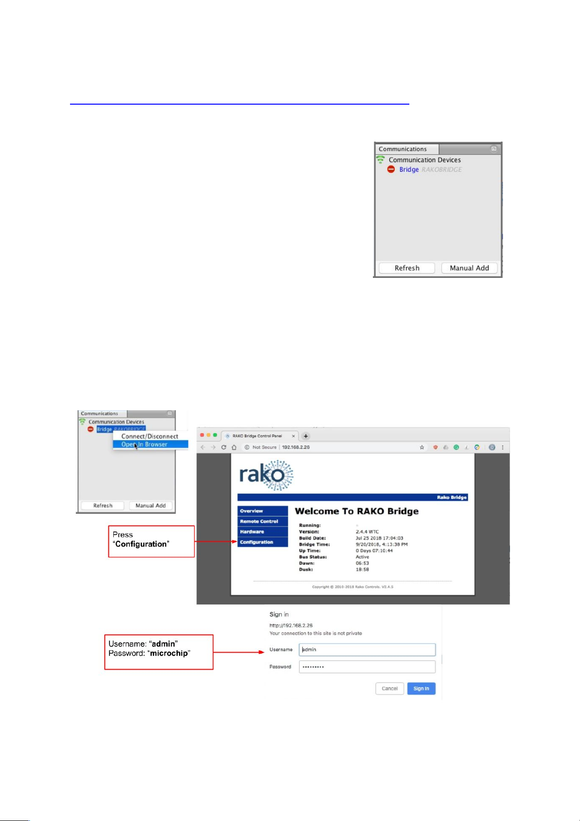
3.1 Discovering the Bridge
Open Rasoft Pro programming software. Ensure that the
laptop is connected to the same network as the Bridge.
The Bridge should appear in the “Communication” window in
the bottom right of the software with a red stop sign. If it does
not appear press “Refresh”.
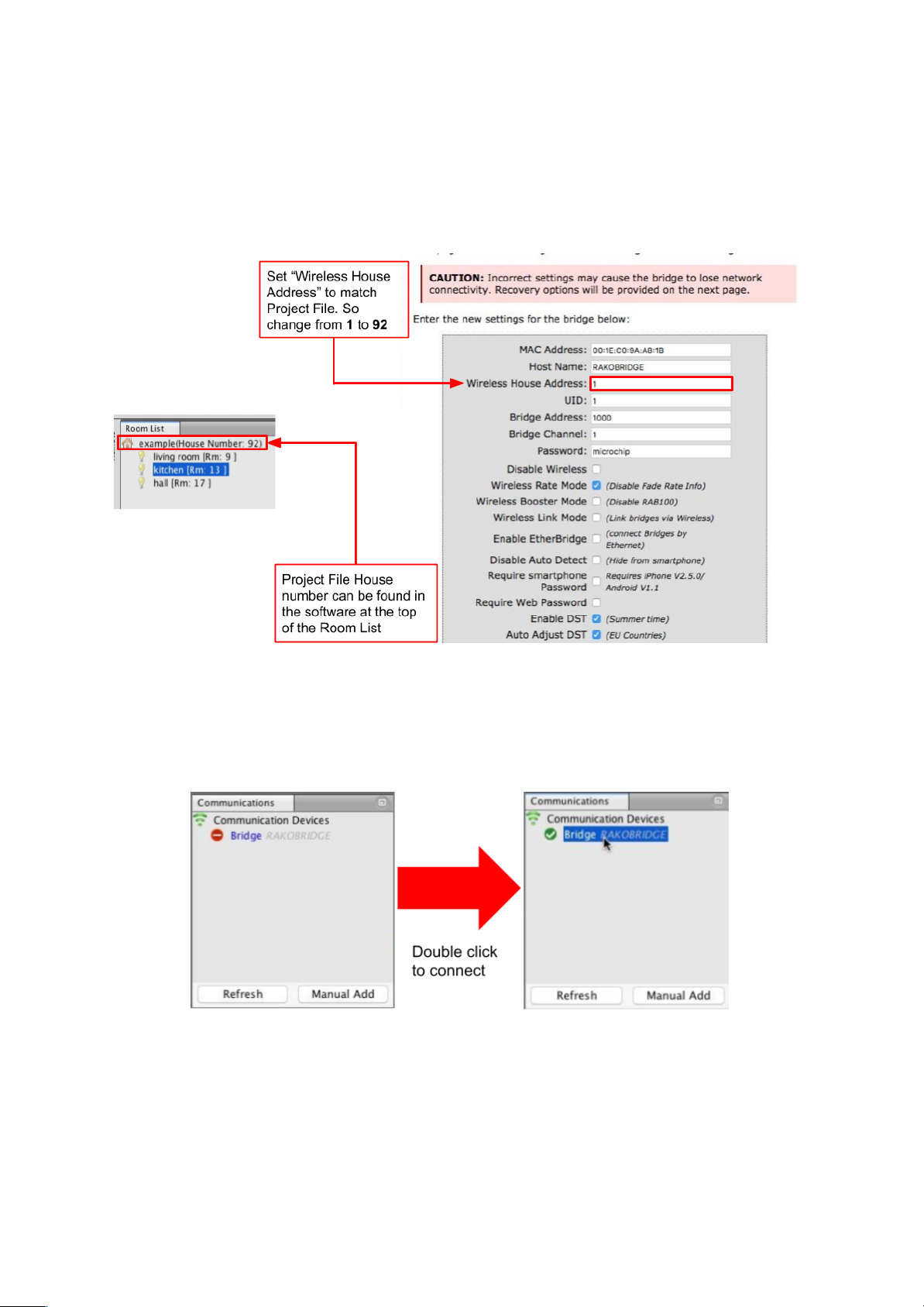
3.2 To set the Bridge House number
The Bridge always has a default House Number of 1. Before beginning any programming
using the Bridge it is important to first set the House number to match the one used when
creating the Project File. Failure to do so may result in interference with other systems.
- Step 1: Right click on the Bridge in the communications window in the bottom right of
the software. Select “Open in Browser” to open the Bridge webpages.
RTC-Bridge Manual Version 2.1.4
Page 4
4
- Step 2: Click “configuration” and enter the username and password.
- Step 3: Fill in the “Wireless House Address” to match the project file
- Step 4: Scroll down and press “Save config” to upload the new House Number to the
Bridge.
The Bridge is now ready to be connected. Do this by double clicking on the Bridge as below.
WARNING
If a pop up box appears with a warning about the House number click “Cancel”. This means
there is a conflict between the “Project File House Number” and “Bridge House Number”.
Do not continue programming. Return to Step 1 of this section and resolve the conflict
before continuing.
RTC-Bridge Manual Version 2.1.4
Page 5
5
3.3 If you cannot connect to the Bridge
If the software cannot connect to the Bridge first restart the software and ensure that it is
fully updated. If the Bridge still does not appear it is most likely a networking issue. If this
problem cannot be solved then the Bridge can be connected to point to point using a
standard ethernet cable.
NB
By default the Bridge is connected via DHCP, this and other network settings can be edited via the
Bridge webpages. It is possible to clear all network settings from a Bridge. Please call Rako technical
support for information on how to do this.
4 Adding the Bridge as a device
Once the Bridge has been successfully connected it will need to be added into the software
as a device.
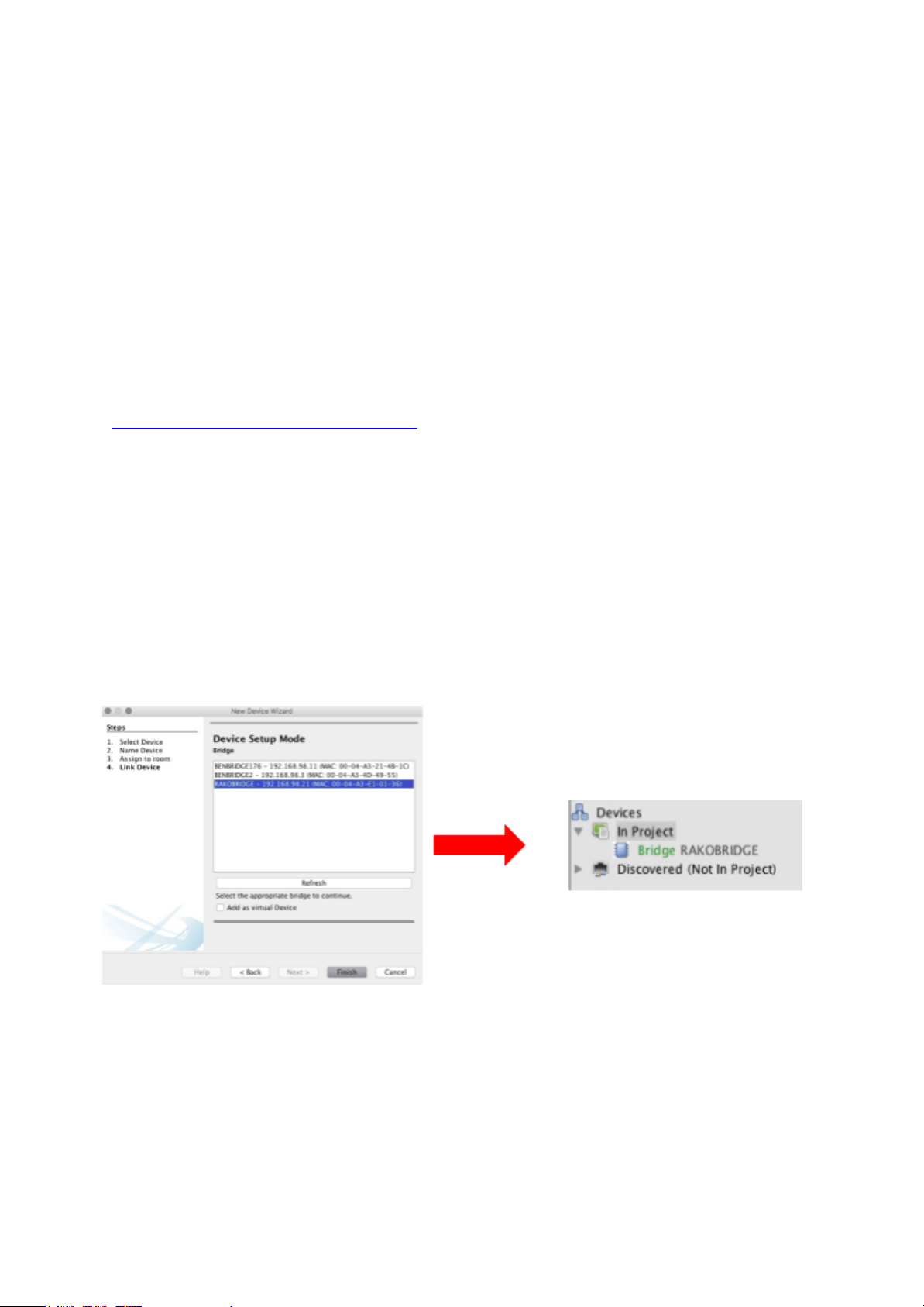
- Select “File”- “New Device” to open the new device wizard. Choose “Bridge” as the
device to be added.
- Select “Next” on the “Assign to Room” step. No room or channel needs to be
associated to the Bridge.
- Select the Bridge from the list, it will appear if you are successfully connected in the
communications window. Click “Refresh” if it does not appear.
- The Bridge should now appear in the device list with green text and a blue icon. The
device is now assigned.
- Press the “Update Now” button in the centre of the screen to complete setup. If this
does not appear click on the Bridge in the device list.
RTC-Bridge Manual Version 2.1.4
Page 6

6
5 Uploading the project file
Once the entire system has been completed the project file should be uploaded to the
Bridge. The Bridge stores the Room, Channel and Scene information for the system. This
information is required for the App. to operate correctly.
The “Smartphone/Web Data” tab is used to upload the Project File to the Bridge. Once
selected it will open the page as below. Press “Save & Upload Room Data To Bridge” to
upload.
Type - This will change the appearance of the icon used at the top of the room screen on the
App. It will also affect the keypad that appears. For example a room set to “switch” will show
two buttons: “on” and “off” whereas a “blind” type room will show three buttons: “open”,
“stop” and “close”.
Mode - The mode of the room is only set when “lighting” is selected as the type. It will set the
variety of “keypad” that will appear in the App. Typically it is best to make this match the
physically keypad in the room.
NB
1) If a number of scenes that is not 4, 7 or 16 is desired then “named scenes” should be
selected. Give custom names to the scenes in the room editor and any number of scenes can
be made to appear on the App.
2) While the order of the rooms can be changed from this screen the order of the channels is
always fixed. To get channels in a specific order they must be addressed or mapped in the
desired order.
RTC-Bridge Manual Version 2.1.4
Page 7

7
6 Downloading the project file
If information has been uploaded to the Bridge then it is possible to import the Room,
Channel and Scene data into a blank project file.
The tab used for downloading information from the Bridge is called “Room Import” select it
to open the page below.
- Step 1: Press the “Download Data” at the top of this page. This will open the data for
preview on this page.
- Step 2: Press “Refresh List” if the rooms do not appear. If no rooms appear or only
“default room” or “test bench” then there is no information to be downloaded from the
Bridge.
- Step 3: Press “Import Data” to write the Room and Channel information in to the
Project File.
- Step 4: Press “Refresh Channel Levels” to write the Scene data in to the Project File.
RTC-Bridge Manual Version 2.1.4
Page 8
8
7 Events
Events can be viewed, added and changed using either Rasoft Pro or the Rako App.
The Bridge can generate automated Events that trigger commands at specific times.
For example it is possible to automatically turn on the Garden lights on at Dusk and turn off
the Garden lights at Dawn.
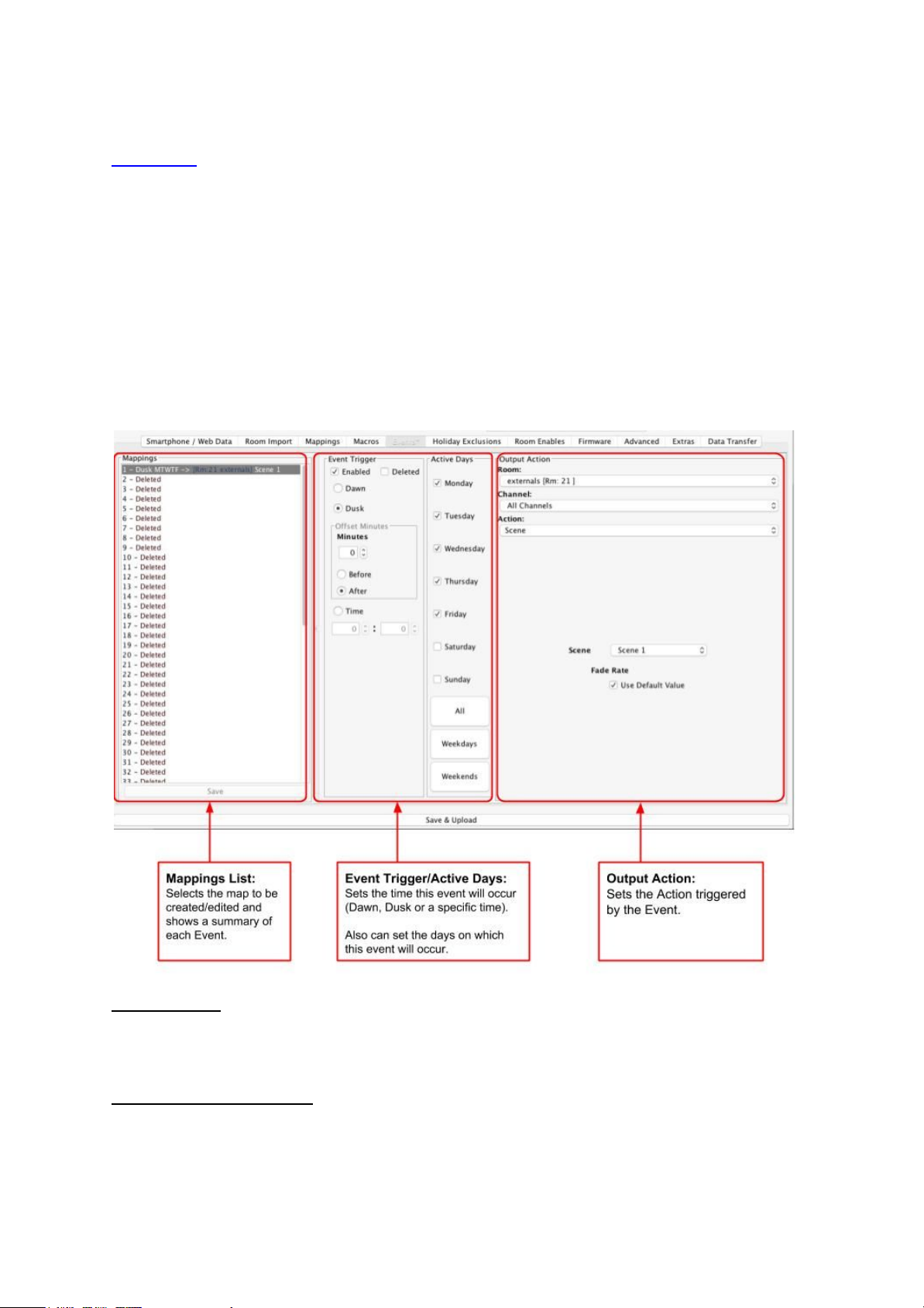
7.1 Setting Events using Rasoft Pro
Bridge Events can be viewed and edited using Rasoft Pro. To open the events page in the
software select the Bridge in the device editor and select the “Events” tab from the top of the
window.
Mappings List:
All Events are listed down the left hand side of the screen. Select it such that it is highlighted
to edit the “Event Trigger/Active Days” and “Output Action” sections for this Event.
Event Trigger/Active Days:
The “Event Trigger” and “Active Days” are the timing conditions that define when the event
will occur.
RTC-Bridge Manual Version 2.1.4
Page 9

9
NB
The dawn and dusk settings can be changed via the location settings in the webpage interface. An
offset from this value can be set from this screen if desired.
Output Action
The Output action section on the right hand of the screen will define the command to be sent
when the conditions in “Event Trigger”/“Active Days” are met.
NB
The “Action” drop down menu is used to select the command sent when the event is triggered.
Typically these will be scene commands but it is possible to trigger and control Macros, Holiday
settings etc.
7.2 Setting Events using the Rako App.
Events can also be created via the Rako App. The method to create events in the App is
essentially the same as detailed above.
NB
It is also possible to set Events from the Bridge webpages if required
8 Mappings
When Mapping are used the Bridge can “listen” to a Rako command (Source) and perform a
certain action (Output Action) every time it is “heard”.
NB
It is usually preferable to use a programmable keypad rather than Bridge Mapping when possible.
Where WCMs are RNCs are used in the system use Keypad Mapping rather than Bridge Mapping.
RTC-Bridge Manual Version 2.1.4
Page 10

10
8.1 Mapping wireless commands to give multi-room functionality
Wireless commands can be mapped to additional wireless commands to make multiple
rooms turn on at once. In the example below the “Hall Scene 1” is mapped to also trigger
“Kitchen Scene 1”.
8.2 Triggering Macros from Maps
When a Macro is used it must be triggered from a map (this could also be from a WCM map,
WAVFR map etc.). Below Mapping 2 is an example of a map being used to trigger a macro:
in this case “Start Macro 2”.
NB
It is also possible to “Enable” and “Disable” maps from other commands via the “Mapping Control”
Action.
RTC-Bridge Manual Version 2.1.4
Page 11

11
9 Macros
Macros allow a sequence of actions to take place when triggered by an Event or Map. The
Bridge can store up to 60 Macros each of which can have a maximum of 32 Steps.
The Bridge Macro screen is located from the tab in the Bridge device editor.
There are 3 steps in this example Macro:
- Room 9, All Channels, Scene 2
- Room 17, All Channels Scene 1
- Room 49, All Channels Scene 2
With this simply Macro the Bridge will just run through the three commands listed. More
complex functionality can be achieved by using commands in the tables outlined below.
9.1 Writing Macros
Macro steps can be one of 4 types:
Action
Pause
Delay
Goto
Can be a simple
command including
Scenes, Fades etc.
Can also include
“Macro Control”,
“Mapping Control” for
more complex
programming.
A running Macro will
stop at a Pause and
remain there until it
hears a Continue.
The Macro can wait at
this step for a defined
period of time. Useful
when programming
PIR timeouts etc.
The Macro can be
sent to a defined step
in this or another
Macro.
RTC-Bridge Manual Version 2.1.4
Page 12

12
9.2 Triggering Macros
Macros can be triggered in several ways. Most commonly:
- Wired device direct Map (WCM/WAVFR/etc.)
- Bridge Mapping
- Bridge Event
Once a macro trigger is sent it will perform one of four different functions to a Macro:
Start
Stop
Pause
Continue
This will cause the
Macro to start from the
beginning (Step 1)
regardless of its
current position in the
Macro.
This will cause a
Macro that is already
running to Stop
running and return to
Step 1.
This will cause a
Macro to Pause at
whatever step it is
currently running.
This will cause the
Macro to continue
from a Pause state,
performing the step
immediately after this
and proceeded.
NB
It is also possible to “Enable” and “Disable” Macros (or parts of Macros) via the “Macro Control”
Action.
10 Holiday Mode
Holiday mode allows the Bridge to record normal lighting activity in a property over a period
of time. This can then be replayed whilst the property is empty in order to give a realistic
impression that it is occupied.
Holiday mode has three states:
- Record: Used to create a log of the used of the system.
- Playback: Used when the house is unoccupied to replay the information gathered in
“Record”.
- Idle: Used when the system is in normal occupied operation and no recording is
being made.
Holiday mode is most easily controlled from the App. However it is also possible to change
the holiday mode state from a keypad map, Bridge map and by pressing buttons directly on
the Bridge.
NB
For how to control Holiday mode via the App. see “App user Guide”.
RTC-Bridge Manual Version 2.1.4
Page 13

13
11 UDP Feedback
It is possible to monitor commands received and transmitted by the Bridge. This can be done
using the UDP Feedback feature.
11.1 Live feedback
In the very bottom right of the software (below the communications window) is the Live
feedback section. Each command received or transmitted by the Bridge will appear here and
it is useful for checking commands have been programmed as desired.
11.2 UDP feedback log
When more detailed or long term feedback is required then a log of commands
received/transmitted by the Bridge can be opened. In the toolbar select “Window” - ”Output” ”Output” (as shown below).
NB
With a timeclock Bridge it is also possible to monitor UDP feedback using “monitor mode” on the
Bridge itself.
RTC-Bridge Manual Version 2.1.4
Page 14

14
12 Performing a Firmware upgrade
To ensure continued access to all features of the Bridge it is advised that it is updated with
the latest firmware if possible. This requires an active internet connection.
Click “Refresh” to see if updates are available. Select “Update All” if updates are available to
perform a firmware upgrade on the Bridge.
RTC-Bridge Manual Version 2.1.4
 Loading...