

Page 1
RSR-DLI User Manual
For an overview of the wireless systems: Wireless Module
Application Sheet / Wireless RAK Application Sheet
For programming a wireless system: Wireless Module
Programming Guide / Wireless RAK Programming guide
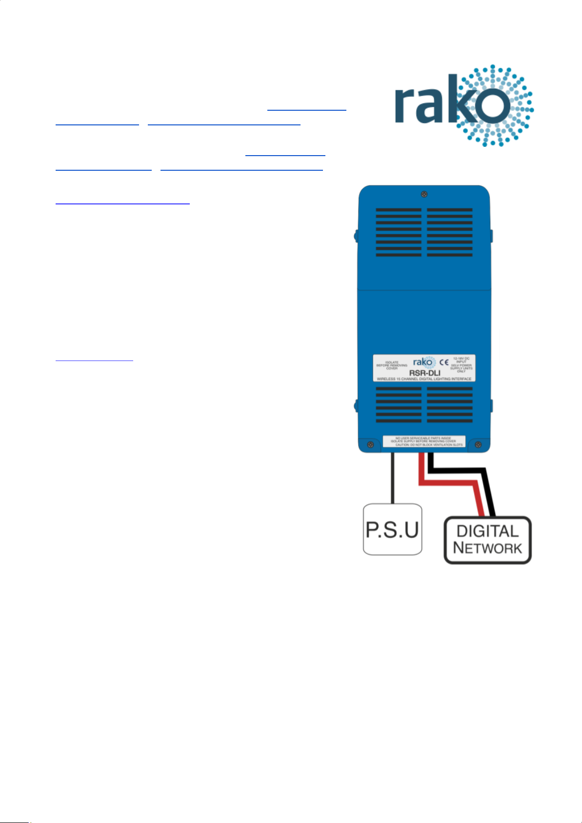
What is the RSR-DLI?
The RSR-DLI allows the integration of an addressable DLI
network into a Rako system. Up to 64 DLI ballasts can be
assigned to 15 different channels in a single room either by
DLI short addresses or by DLI groups. Auto-heal
functionality for easy replacement of faulty ballasts is also
available.
What is DLI?
DLI is a protocol by which a network of compatible ballasts
can communicate with each via bi-directional data
exchange. Ballasts are assigned a unique address
between 0 and 63 (called a Short Address) so they are
identifiable to the DLI controller (RSR-DLI).
Three different types of commands can be sent across the
DLI network.
Direct – A command sent to a single ballast (short
address).
Group – Ballast can be associated to one another within a
network by using DLI groups. A group command will be
sent to all Ballasts within the DLI group.
Broadcast – A command sent to every ballast on the DLI
network.
RSR-DLI Manual Version 3.0.3
Page 2

Installing the RSR-DLI
The RSR-DLI works off a 12V DC, a suitable power supply attached to a 13A plug is provided with
the product. When successful powered up LED 2: the “Power LED” will illuminate.
Note that this power supply is to power the circuit board and DLI output of the RSR-DLI only. The
power for the fittings themselves is provided directly to the ballast, the output from the RSR-DLI is
a control signal only.
Adding the RSR-DLI as a device
For the RSR-DLI to operate correctly with a Rako system some initial
setup must be performed. This is done using a PC running Rasoft Pro
(RSR-DLI is not supported by RASOFT classic) and communicating via
a RAKO Bridge/HUB or RAMPI programming device.
Open the Project File for the installed Rako system and make sure that
Rasoft is connected to a communication device.
NB
The communication window at the bottom right should indicate whether a device is connected or not. In this
case a RAMPI is connected. For instructions on how to connect to a communication device see Rasoft Pro
programming guides and applicable instruction manuals.
- Select “File” - “New device” to bring up the “New device Wizard” and choose “RSR-DLI” from the
list.
- Choose a suitable device name (if you have multiple RSR-DLIs make sure it is identifiable from
this description). Leave “Device ID” blank with the “Automatic ID” box checked.
- Associate the RSR-DLI to a room from the drop down menu. The room selected here will set the
“Local Room” for this device.
RSR-DLI Manual Version 3.0.3
Page 3

- Once this screen appears press and hold the blue button on the RSR-DLI. After a few seconds it
will enter Setup Mode and the status LED will start to blink. Release the button and the status LED
should continue to cycle.
-Press “Device is in setup” and then “Finish” to send the addressing signal to the device. The LEDs
should stop cycling and flash on if the addressing signal is successfully received.
The RSR-DLI is a multi-channel device and will occupy the entire room. By default Short Address 0
will be addressed to Channel 1 in the Rako Room, DLI Short Address 1 to Channel 2 and so on for
all 15 Channels.
Addressing the DLI Ballasts
At this stage the RSR-DLI has been addressed and the Rako channels are associated to DLI short
addresses. However the ballasts themselves do not have DLI short addresses assigned to them.
To address the DLI ballasts open the “DLI Setup” tab in the RSR-DLI device editor (select the
RSR-DLI in the device list to open the device editor).
RSR-DLI Manual Version 3.0.3
Page 4

Force Readdress:
This will delete all current short addresses and replace them with an entirely new set. It is
advisable to use this button when initially addressing the DLI ballasts in a new system.
Automatically Readdress:
This button will assign DLI short addresses to any Ballast that is unaddressed. If additional ballasts
are added this will assign addresses to the new ballasts while leaving the previous addresses
unaffected.
Mapping the DLI ballasts
To use the Circuits mapping page “Use group mapping” must be selected. When in “Use
Direct mapping” mode Rako channels will always be set as DLI short addresses -1 (DLI
short address 0 = Rako channel 1, DLI short address 1 = Rako channel 2 etc.) regardless of
how the mapping page appears.
Sometimes it may not be desirable to have the DLI channels arranged in the order they have been
auto-assigned using “Automatically Readdress” or “Force Readdress”. This is achieved using the
Circuits (Mapping) tab in “Use Grouped Mapping”.
When “Use Grouped Mapping” is selected the Rako channels become mapped to DLI groups. This
means that any number of DLI short addresses can be mapped to a single Rako channel and in
any order. This is useful if more than 15 DLI short addresses need to be assigned to a single
RSR-DLI or if the ballast(s) are not set to the desired Rako channel.
It is possible to test which ballast is associated to which short address by using the test column on
the mappings page. Double click on “test” to send and “on” to this ballast, double clicking again will
send an “off.” When an “on” is successfully sent the row will appear as below.
Shortcut commands exist for testing individual DLI short addresses, select the column of the short
address to be tested first
The <, key = Send on
The >. key = Send off
The ?/ key = Toggle on/off
RSR-DLI Manual Version 3.0.3
Page 5

Auto Heal Data
When programming is complete press this button to store DLI network information. Failure
to do so will mean in the event of lamp failure the entire DLI network will need to
re-programmed.
This button will store the current state of the DLI network within the RSR-DLI. This means that if a
single ballast is removed and replaced the new ballast will have the same short address
automatically uploaded to it. If more than one DLI ballast needs to be replaced the entire network
must be re-addressed using the “Force Readdress” button.
Extra features of RSR-DLI
Swap Channels
The Swap Channels tile in the DLI setup tab allows for custom readdressing of the DLI short
addresses themselves. Individual short addresses can be moved on to or swapped with each other
by using this interface.
This will readdress the DLI ballast to the short address as set in each box, “Perform Swap” will
directly switch the position of the two ballast. “Perform Move” will result in both ballasts having a
the short address of “DLI Short Address 2”.
Visible Channels
Sometimes not all 15 channels in the room will be required by the RSR-DLI (less than 15
separately controllable sets of DLI ballasts required). When this is the case then the “Visible
Channels” tab can be used to reduce the number of channels the RSR-DLI occupies in the
software.
Slide the “channels used” slider to match the number of Channels required by the RSR-DLI and the
remaining channels are freed up to be used by other devices.
RSR-DLI Manual Version 3.0.3
 Loading...