

Page 1
RMR-VF User Manual
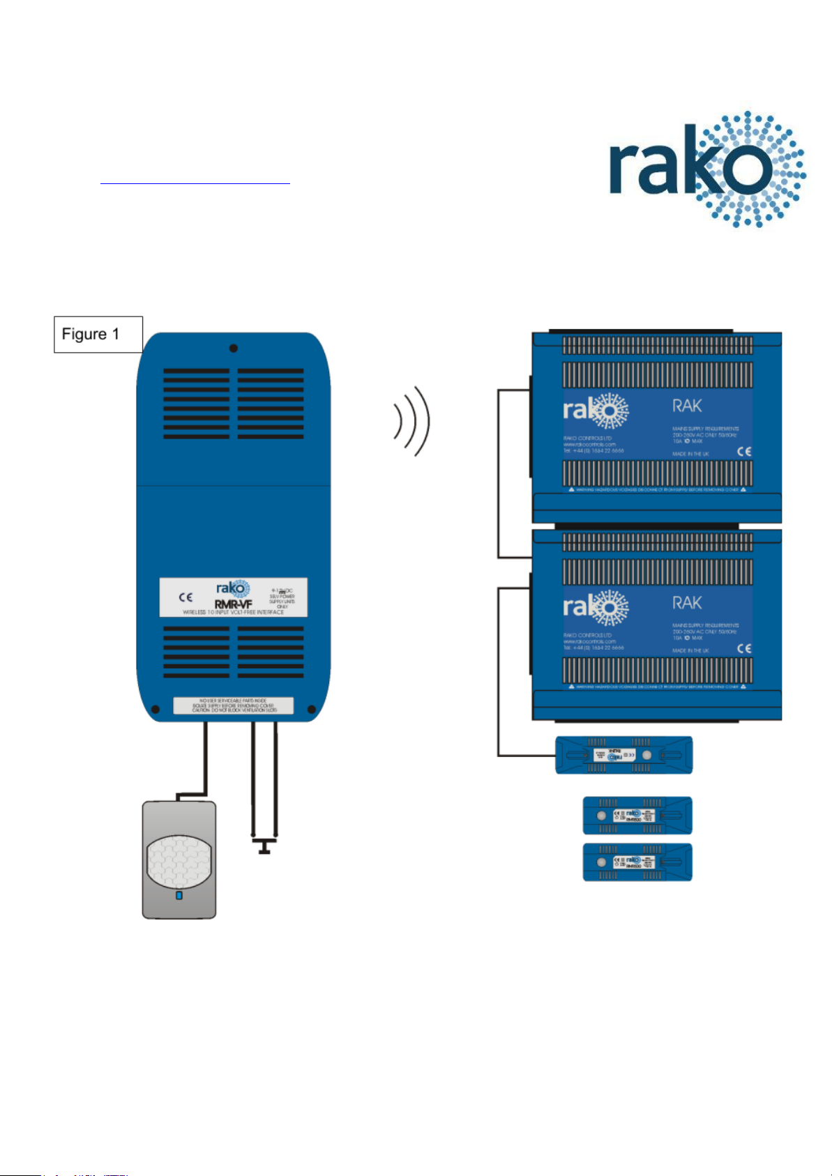
What is the RMR-VF?
The RMR-VF allows mechanical switches and logic levels to add
additional control of a Rako Wireless system. Signals can be taken from
anything that can provide a contact or DC logic output such as m Alarm
sensors, PIR modules, Thermo sensors, Light detectors etc.
RMR-VF Manual Version 2.0.0
Page 2
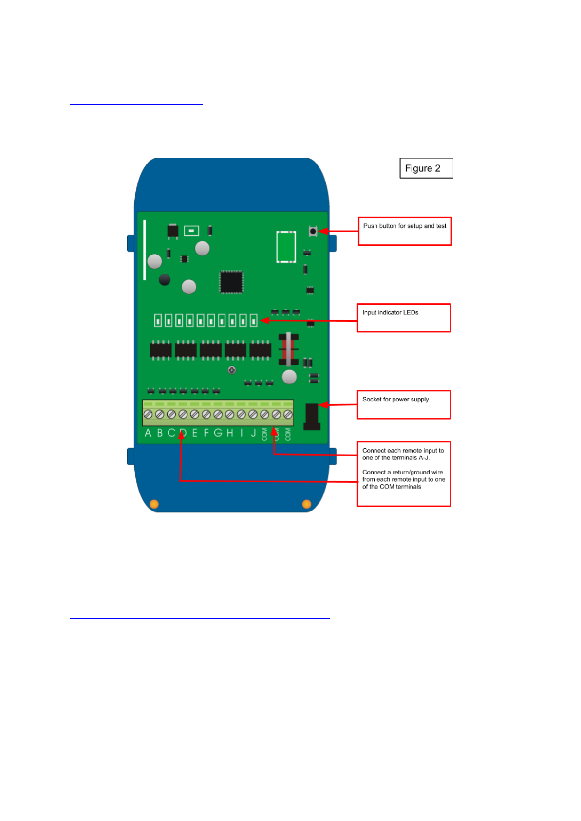
Installing the RMR-VF
The RMR-VF requires an AC power adaptor and should be plugged directly into a 13A plug
using the supplied power adaptor.
NB
Two LEDs will light on the RMR-VF circuit board. The “Power” LED in the top left of the board
indicates that correct volts are being received from the power adaptor. The LED “D25” near the
terminal blocks shows that the RMR-VF on-board supplies are active (power to the terminal blocks).
Configure the RMR-VF using RASOFT Pro
For the RMR-VF to operate correctly with a RAKO system some initial setup must be
performed. This is done using a PC running RASOFT Pro (or Rasoft classic) software and
communicating via a RAKO Bridge or RAMPI programming device.
RMR-VF Manual Version 2.0.0
Page 3

Open the Project File for the installed Rako system.
Make sure that Rasoft is connected to a programming device.
The communication window at the bottom right should indicate
whether a device is connected or not. In this case a RAMPI is
connected.
Add the RMR-VF as a device.
- Select “File” - “New device” to bring up the “New device Wizard”
and choose “RMR-VF” from the list.
- Choose a suitable device name (if you have multiple RMR-VFs make sure it is identifiable
from this description). Leave “Device ID” blank with the “Automatic ID” box checked.
- Associate the RMR-VF to a Room from the drop down menu. The room selected here will
set the “Local Room” for this device. Which room this is is relatively unimportant as a
command can be sent to any room in the project using the “Mappings” for this device.
- Once this screen appears press and hold the blue button on the RMR-VF. After a few
seconds it will enter Setup Mode and the LED’s A, B, C, D, E on the RMR-VF will start to
blink. Release the button and the Input LEDs should continue to cycle.
- Press “Device is in setup” and then “Finish” to send the addressing signal to the device.
The LEDs should stop cycling and flash all on if the addressing signal is successfully
received.
NB
Once “Finish” is pressed the software will assume that the RMR-VF has been set up successfully and will appear
as an addressed device in the device list. This will be the case regardless of whether or not the unit was actually
addressed. It is a good idea to verify that the RMR-VF has been addressed, do this by right clicking it in the
device list and selecting “Ident Device”. The RMR-VF should pulse solid once for around two seconds on all the
input LEDs if addressed successfully.
Programming the RMR-VF functions
A RMR-VF has a maximum of 24 maps that can be set. Each is programmable by selecting
it in the mappings list and then editing the three sections: “Inputs”, “Mapping Options” and
“Output Action”.
Inputs
The ten inputs of the RMR-VF “A-J” are represented by these buttons and correspond
directly to the lettered terminal blocks on the circuit board. Each can be set to, “Normal”,
“Ignore” or “Invert” by clicking on the tile.
Normal – Used to select this input as the trigger for the map.
RMR-VF Manual Version 2.0.0
Page 4

Ignore – The state of an input set to “Ignore” for a particular map will not affect whether the
output action occurs or not.
Invert – Use only when combined inputs are required: see Application sheet (LINK)
“Combing Volt free inputs” for further information.
Take the example map shown in Figure 4. This map has a very standard configuration, as a
single input is causing a single command to be outputted. The input is “A” so this is set to
normal and all other inputs are set to ignore.
Mapping options
The mapping options are used to define additional parameters that must be met for the
“Output action” to occur.
Trigger on Make/Break:
Sets the type of signal the RMR-VF will respond to. Typically normally open devices will be
set up as “Trigger on make” normally closed as “Trigger on Break”. A map set up as trigger
on Break will have “RLS” after the letter in the mapping list (see map 2 in figure 4).
Input longer/shorter than:
Allows the RMR-VF to differentiate between inputs applied for different lengths of time. Use
the slider below the drop down menu to set the time condition that the longer/shorter than
will apply to.
RMR-VF Manual Version 2.0.0
Page 5

Don't update previous room:
If this box is ticked this map will not update the “last used” flag for both room and channel.
When a “last used” is sent from this device the most recent room and channel sent which
doesn't have “don't update previous room” selected will be sent.
Set Scenes only if lights are OFF:
Ticking this box means that if the command sent in the “output action” section is a scene it
will only take effect if the lights are currently off. This is often used when the device
interfacing with the RMR-VF is a presence sensor.
Any input Trigger (OR Logic):
Use only when combined inputs are required: see Application sheet (LINK) “Combing Volt
free inputs” for further information.
Output action
This tile is used to set the command sent from the input defined in the other two sections.
Before being altered the room will be the local room for that keypad. All the rooms in the
project will be in the drop down menu as will an option for “previous room”.
The next drop down menu can be used to change the channel affected by this command.
Usually “all channels” is selected so that the entire room will be affected by this map. All the
channels added in the room editor will appear in this drop down menu as will “last used” and
“custom”.
NB Previous room/channel will set the room number to that which was last sent by this device. It will
not track commands sent by any other device.
The last used function sets the channel to the most recent previous command sent from that
device. This is commonly used when a WCM is set up to toggle individual channels. In this
case “last used” is used for the fade buttons so that the user can adjust the brightness of the
channel they have just turned on.
The action sections sets which command will be sent to the room and channel that have
been set.
RMR-VF Manual Version 2.0.0
 Loading...