

Page 1
Rako RLED20CC3 Installation, Programming and Operating Instructions
General
Rako RLED20CC3 modules are three channel, constant
current dimmers with a maximum rating of 20W per
channel for use with 3 colour constant current LEDs. The
module is designed to directly control LEDs with no
additional drivers. The output current rating can be set to
give 350, 500, 600, or 700mA. They are designed to
accept DC power from a suitably rated power supply up to
a maximum of 48V DC. The RLED20CC3 can be used with
fittings with either separate or common negatives.
Important
Do not connect directly to a 240V mains supply.
Installation should only be carried out by a competent
electrician.
Never attempt to connect a Rako module or remove the
terminal cover without first isolating the circuit at the
fuse/MCB board.
The circuit supplying a Rako module should always be
protected by either a 5A fuse or 6A MCB.
Mounting
Rako modules should be mounted in areas that are
adequately ventilated, dry and outside of any enclosed
metal casings that may interfere with the wireless signal.
Wherever possible the mounting bracket should be used.
Modules should be mounted vertically or horizontally with
the ventilation slots at the top.
Whilst Rako modules are designed to be completely
maintenance free the units should be mounted in an
accessible location should there be a fault or re-addressing
of the unit be necessary (see 'Set-up and Addressing')
Loadings
The permissible loadings depend on several criteria
keeping within the maxima for the unit of 20W per channel
and a forward voltage of 45V. For the purposes of
calculating the total forward voltage of an LED fitting refer
to the manufacturer's data.
Channel Addressing
When giving the RLED20CC3 a Rako channel address the
next 2 channels are automatically assigned, sequentially
from this point. For example, a module controlling an RGB
fitting and addressed as channel 3 will control Red on
channel 3, Green on channel 4 and Blue on channel 5.
Connections
Connect the RLED20CC3 module according the wiring
diagram overleaf. Note the supply should be from a
suitable DC power supply with an adequate power and
voltage rating. The power supply should have a minimum
voltage of 24V and a maximum of 48V and needs to give
adequate forward voltage to drive the lamps connected.
The internal voltage drop is approximately 3V giving an
effective maximum output forward voltage of 45V.
As with all constant current LEDs fittings should be wired in
series.
Use the header connector to select the required output
current. The default with no header connected is 350mA.
Do not use loop In/Out connections within the module. A
junction box should be used if required.
Ensure the cable clamp bar securely clamps the cables and
that the terminal cover is fitted before switching the supply
on.
Initial Checks
When power is initially connected to the module the unit
should switch the load ON. The load can then be manually
switched using the clear button on top of the module.
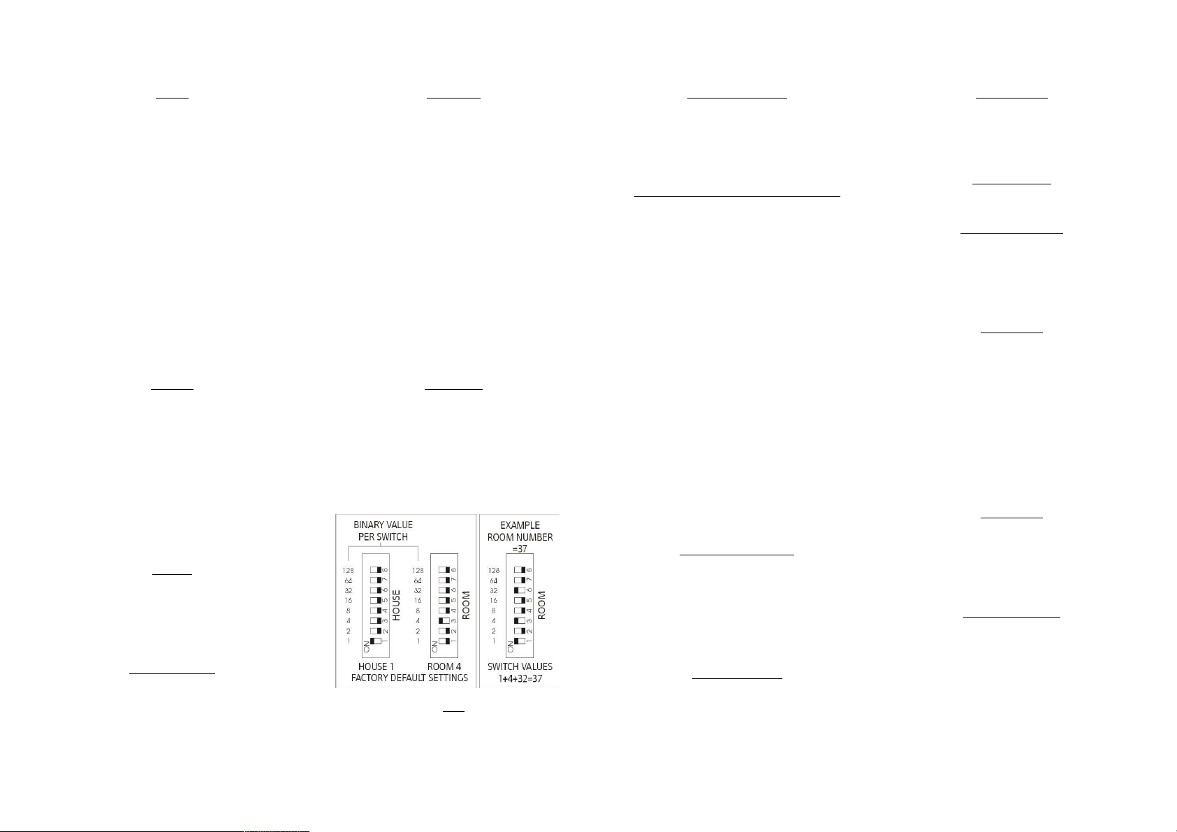
The factory set address for both modules and transmitters is
House 1 Room 4 (See Fig 1 for further information). A
Rako wireless wallpanel set as address House 1 Room 4 will
control and dim the module.
Should the module not respond as above then further
investigation should be made before proceeding further.
Fig.1
Set-Up and Addressing
RLED20CC3 modules can be programmed manually or by
using RASOFT programming software. For software
programming refer to the appropriate programming guide
supplied as a PDF with the programming interface (RA or
RTC-Bridge etc.) or download from our website:
www.rakocontrols.com.
Manual Addressing from Wallplate or Handheld
Before any lighting scenes can be programmed (see the
wall-panel or hand-held manual) the RLED20CC3 module
needs to be addressed.
To avoid interference between neighbouring installations
choose a House address other than the factory default of
House 1 and set this on the transmitters using the House
address switches. Keep the House address the same
throughout the project (for master functions).
Choose a Room address for each separate room or area to
be controlled independently and set this on the appropriate
transmitters using the Room address switches. Note: Any
control panels set with the same address will act as two or
multi-way controls for the same Room.
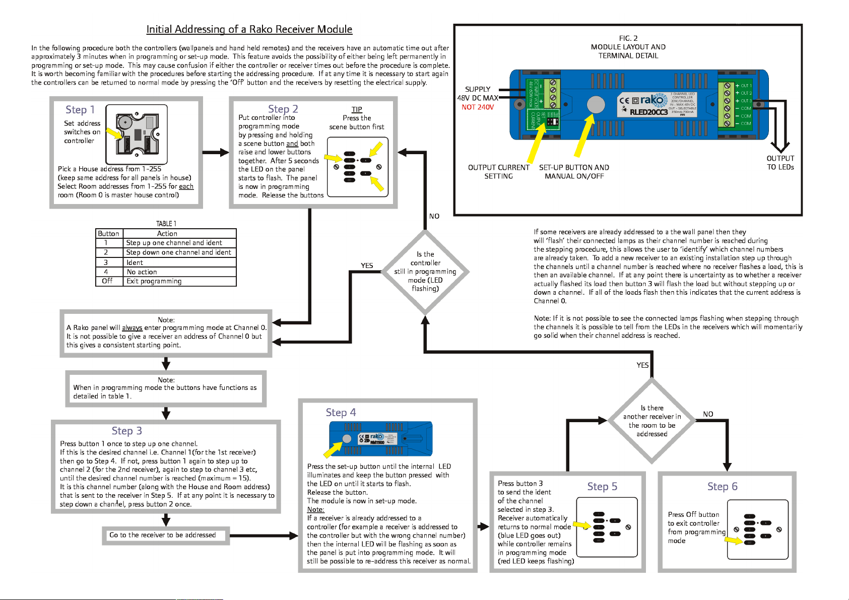
The module now needs to be sent its new House and Room
address from the appropriate keypad. For rooms with
multiple modules each module needs to be also assigned a
separate Channel number from 1-15 within each Room.
The House and Room addresses are set using the switches
on the back of a Rako transmitter (see Fig 1) and the
Channel addresses are selected by putting a transmitter in
programming mode and ‘stepping’ through the channel
numbers (see Step 3 overleaf). This number is then 'sent'
(along with the House and Room address) to a receiver
(Step 5).
Notes on address switches
The address numbers are set using the switches on the back
of a Rako transmitter. Binary coding is used and a
diagrammatic explanation is given in Fig 1. It is not
however necessary to understand binary just set the House
switches to a different setting than the factory default and
use a different combination of Room switch settings for
each room or area to be controlled separately.
Notes on Addressing
A dimmer cannot be set to an address of House 0 (All
switches set to off)
A dimmer will respond to, but not receive an address of
Room 0 (All switches set to off). This Room 0 address is
used for ‘Master House’ control
A dimmer cannot be set to channel 0.
To program a lighting scene see Wall panel or Hand held
manual.
Power-Up Mode
With the factory address setting of House 1 an
RLED20CC3 will turn ON when power is applied. When
the House address is changed the Power-Up mode
becomes 'OFF' which is generally preferred, for instance
if there is a power cut during a holiday.
Manual Operation
The clear button can be used as a manual On/Off
switch.
Multiple Control Panels
If the module is to be controlled by two wall or handheld transmitters it is only necessary to address the
module to one of these transmitters. Set the other
transmitters to the same House and Room address and
they will transmit exactly the same message as the first
transmitter and the module will respond accordingly.
LED functions
The internal LED behind the clear button will flicker
when the module receives ANY Rako wireless message
and is a useful diagnostic indicator. This function
becomes inactive after 20 minutes to avoid nuisance
light spill but can be re-activated by pressing the clear
button.
If an RLED20CC3 module has already been addressed to
a wall-panel the internal LED will start to pulse as soon
as that transmitter (or any other transmitter with the
same address) is put into programming mode. The
module can still be re-addressed in the normal way, for
example when changing its Channel address within the
same Room.
Colour Cycling
As a default setting the RLED20CC3 module will not
dim from Fade Up/Down commands from a Rako
transmitter but instead will start a colour cycle through
the colours programmed for Scenes 1–4 when it
receives a Fade Up command. A Fade Down command
will stop the cycling
Care and Maintenance
A Rako module contains no user serviceable parts.
Should for any reason you need to contact us please
contact us via our website www.rakocontrols.com or by
phoning our customer help line on 01634 226666.
Page 2
 Loading...