

Page 1
RAVFR Rako Volt Free Switch to Rakom RF Interface – Installation and Operating Instructions.
General
The Rako RAVFR is a volt free contact to Rakom RF interface. Volt-free
contacts can be used to select 4 scenes and off plus the master raise and
lower functions. The volt-free inputs could be from contact closures of an
alarm system, entry gates, passive infra red device etc, allowing simple
wireless interfacing to the Rako control system.
Basic configuration can be achieved using standard Rako control panels
or hand controllers but the Rasoft software package and PC node are
required for access to more advanced user functions.
Fixing Screws
Terminal
Protective
Interface
Housing
Ext aerial &
Fig 1.
Front View of Components
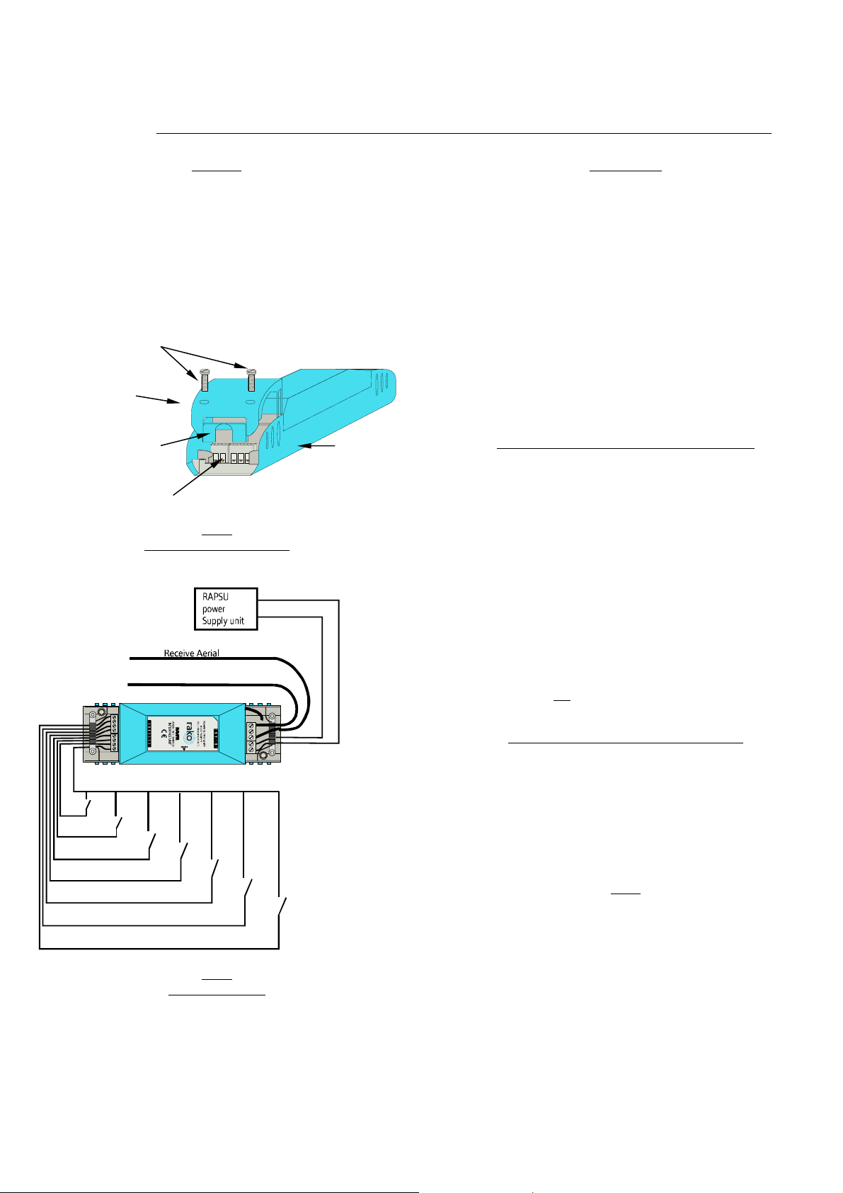
+12V DC
0V
To be mounted at 90° to the direction of the transmitters
External Transmit Aerial
To be mounted at 90° to the direction of the receivers
1
2
3
4
Off
Raise
Lower
Common
Master
Lowe r
Master
Raise
Off
Tx
Gnd
Rx
0v
+12v
Scene
4
Scene
3
Scene
2
Fig 2.
Connection Detail
Scene
1
Before commencing installation of the Rako RAVFR interface module first
read this instruction manual carefully.
Rako Controls Ltd accepts no responsibility for any damage or injury
caused by incorrect installation of a Rako product.
The RAVFR is designed to interface volt-free contacts to the Rako control
system. Up to 7 contact closures can be connected to the RAVFR
allowing selection of the four scenes, raise, lower and off functions. As
standard switch inputs should be normally open although this can be
altered if the user has access to the Rasoft software package.
The RAVFR unit requires the use of the RAPSU external power supply or
other 12V d.c. power supply conforming to SELV requirements. Connect
the power supply and the volt free switch inputs as required and as shown
in Fig. 2 opposite.
Setting the RAVFR House and Room addresses.
In order for the RAVFR unit to control the appropriate Rako receiver
modules it is necessary for the unit to be set to the same House and
Room address as those receivers.
The procedure for setting the address is as follows: (Refer to individual
sections for details on each procedure).
• Put a wall plate (or RAH07 hand controller) that currently
controls the appropriate receivers into programming mode.
• Put RAVFR module into set–up mode using the magnet
provided.
• Press the ident button.
• Exit programming mode on wall plate.
(The above Ident function is also available from the RASOFT software
package, allowing the unit to be addressed without using a wall panel.
Simply select the relevant house and room address on the main screen,
ensure the channel is not
receiver must be in set-up mode.)
Putting Wall plate into programming mode.
Press and hold a scene button (one of the four numbered buttons on the
left hand side of the plate) and at the same time press and hold both the
raise and lower buttons (the right hand buttons). After 3 seconds the
LED will start to flash, the plate is now in programming mode. To exit
programming mode press the Exit button (see Fig. 4).
To select an appropriate channel, press button 1 at least once and not
more than 15 times (this selects a channel address other than 0, which is
not valid).
If the Exit button is not pressed or any other buttons pressed the panel
will exit from programming mode automatically after 3 minutes.
Installation
set to ‘ALL’ and then hit the Ident button. The
Note:
Issue 1 – October 2003 Page 1
Page 2
Scene buttons
p
prog
LED indicator
Master raise and
lower buttons
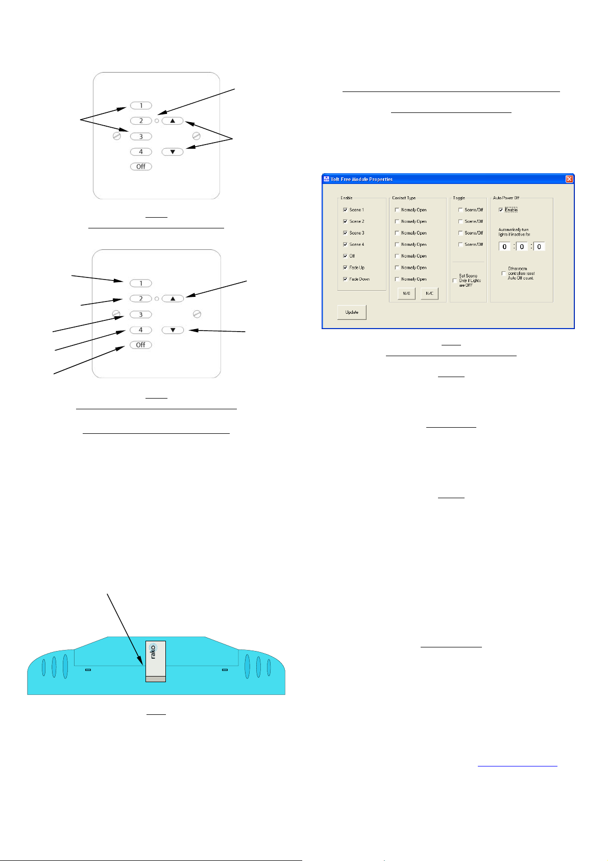
Advanced Functions (requires Rasoft software package)
Configuration of switch inputs.
Open the RASOFT program and on the main screen select the Controls
menu then Volt free setup. This opens the screen as shown in Fig 6.
below. Having selected the appropriate settings for the module clicking
the Update button will then download the settings to the RAVFR module.
Fig 3.
Channel
scroll u
Channel
scroll down
Ident
Store
Exit
Wall-plate buttons in normal mode
Fig 4.
Wall-plate buttons in programming mode
Putting the RAVFR into set-up mode.
The RAVFR is put into set-up mode as follows:
Firstly ensure that the unit has been connected correctly, then, using the
small magnet provided with each receiver, press the magnet against the
receiver casing just over halfway down (see Fig.5). The approximate
position for this is indicated by the ‘magnet point’ legend on the top
label. When the magnet is in the correct position an internal LED will
illuminate. The LED will stay on with a steady illumination all the time
that the magnet is in the correct position. Hold the magnet in this
position for 3 seconds until the LED starts to flash. The receiver is now in
set up mode.
Approximate position for Rako
ramming magnet.
Level up
Level down
Fig 6
Volt free setup screen in RASOFT
Enable
As standard all of the inputs are enabled but un-checking the Enable
check box disables an input.
Contact type
The default setting for a RAVFR unit is to accept normally open switch
inputs. This can be changed to normally closed either for all inputs by
clicking the main N/C button at the bottom of the Contact type panel or
for individual inputs by checking each inputs check box.
Toggle
Each of the four scene inputs can be activated to toggle between their
respective scenes and Off. Ticking the relevant scene box activates this
function which could be used for connecting momentary push switches to
the Rako system.
The other check box in this section is “set scene only if lights are off”.
This feature will only allow an inputs to trigger a scene change if the
lights are in the off state. This is particularly useful if, for example, the
switch input is from an occupancy sensor and it is not desirable to have
the sensor continuously trying to turn the lights to ‘full’ while someone is
in the room. As the unit continuously monitors other devices in the room,
it is aware of the current state of the lighting and can thus correctly
sequence the above functions.
Auto power Off
Magnet
Fig 5
To send a valid address to the RAVFR unit press button 3 on the control
panel (with the panel in programming mode and a valid channel
selected). This will now send the House and Room address of the control
panel to the RAVFR module, which once it receives the Ident command
the RAVFR module will automatically drop out of set-up mode.
If the auto power off is enabled the Off scene will be selected after the
time specified in the time box. The timer is reset whenever an input is
received on the RAVFR. The timer is in HH:MM:SS with a maximum delay
time of 35:59:59 allowed.
By selecting the check box ‘other room controllers reset auto off count’
then the selection of a scene from any other device in that room will also
reset the delay counter.
Rako thanks you for having purchased a Rako product and hopes that
you are pleased with your system. Should for any reason you need to
contact us please contact us via our website www.rakocontrols.com
phoning our customer help line on 01634 226666
or by
Page 2
 Loading...