

Page 1
RAK-LINK Instruction Manual
For programming information: Wired system Programming Guide
For further installation information: Wired RAK Application Sheet
What is the RAK-LINK?
The RAK-LINK is a required element of any wired system.
The RAK-LINK powers the wired network and also provides a link between the keypads and
RAK dimmers.
Up to 32 RAK circuits can be used per RAK-LINK. These 32 circuits can be designated in
any combination of RAK8s and RAK4s.
The RAK-LINK supports up to approximately 40 wired devices communication devices in a
typical installation of 1000m of data cable. “Wired communication devices” refers to WCMs
(keypads), WAPIR (motion sensor) etc.
For a more exact calculation of power requirements please refer to “RAK-LINK diagnostics”
application sheet.
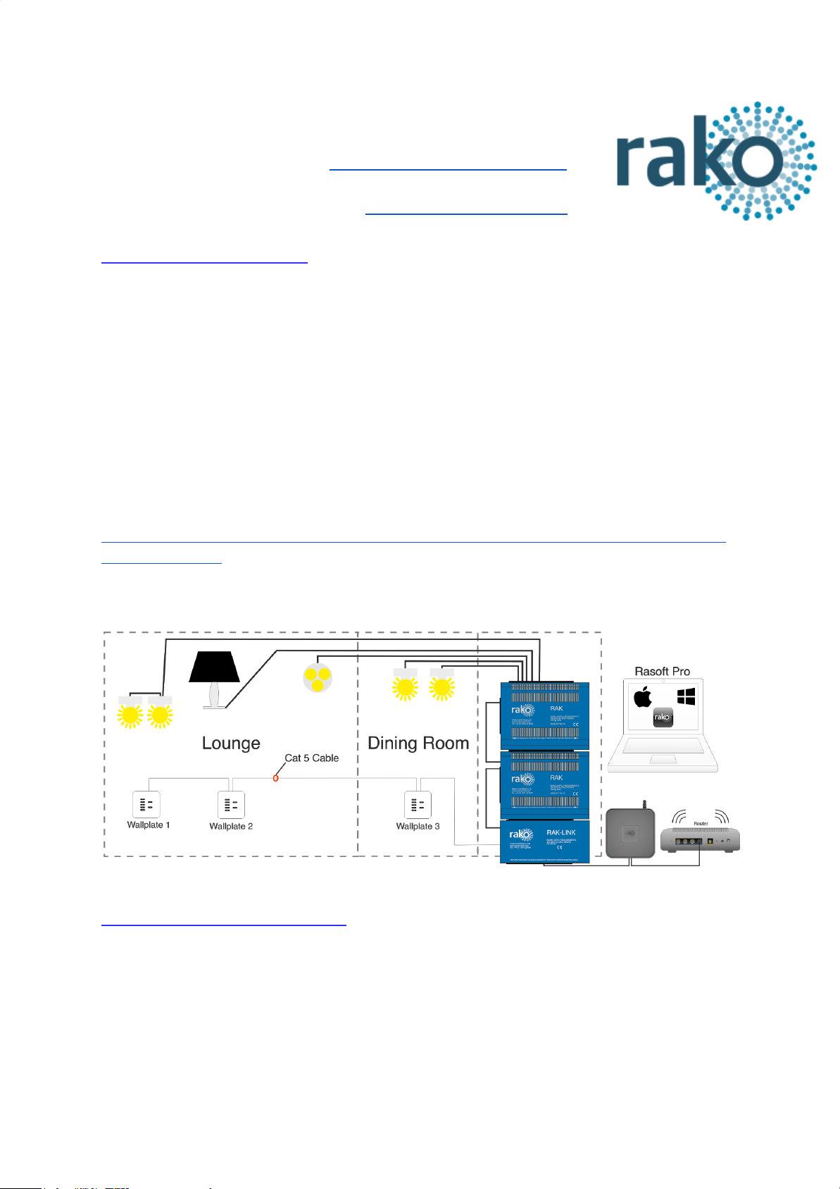
Typical Wired Installation layout:
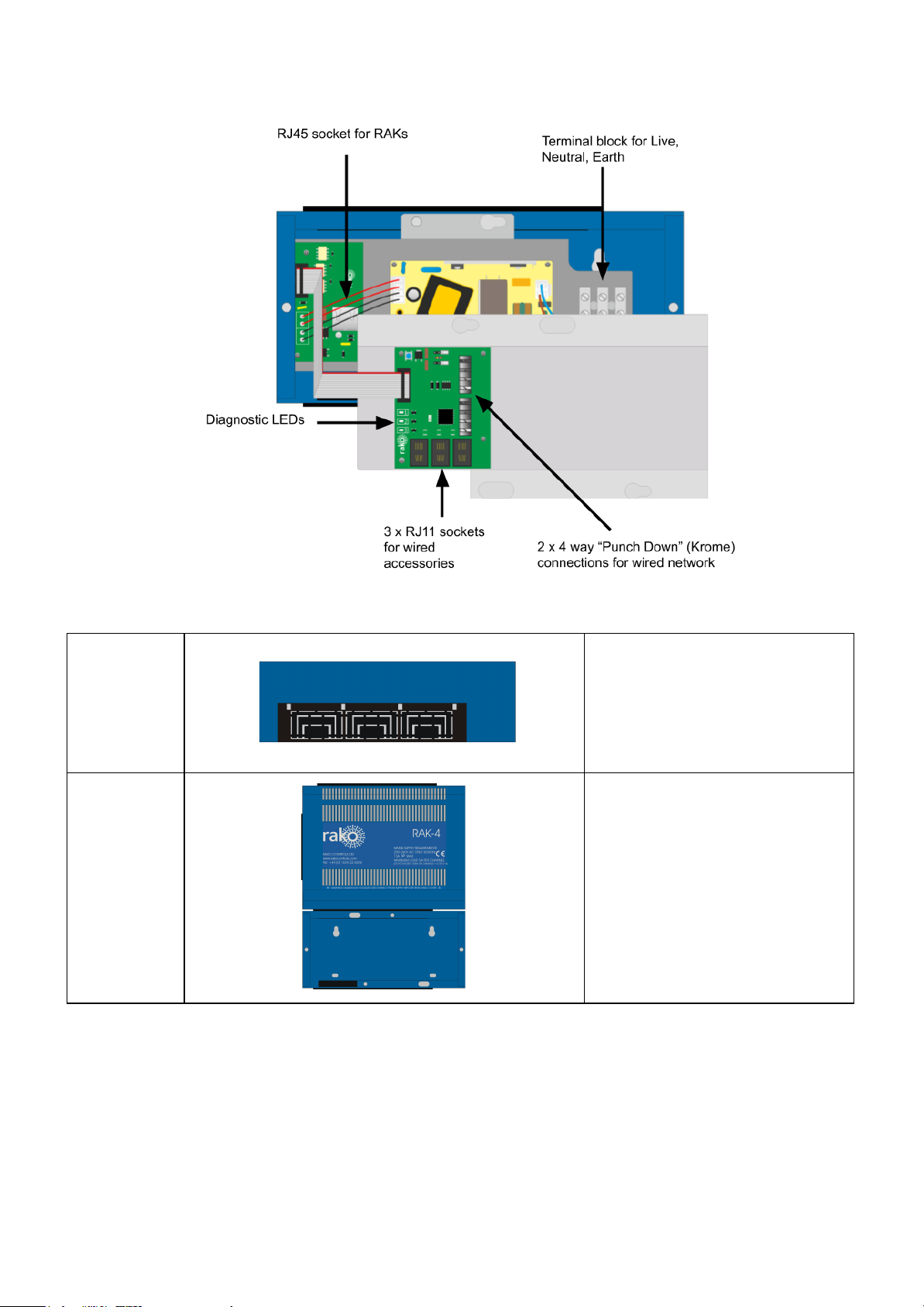
Installation of the RAK-LINK
The connections to the RAK-LINK, as shown below are:
1) Mains AC connection to power supply
2) RJ45 patch lead to RAK stacks
3) Krone connector punchdowns and RJ11 sockets to wired network
4) Optional 3 x RJ11 sockets for wired accessories
RAK-LINK Manual Version 3.1.2
Page 2
Step 1
Remove lid.
Remove plastic knockouts to
allow cables to pass in and out of
RAK-LINK.
Step 2
Slot the RAK-LINK housing into
the RAK metal work
Screw RAK-LINK to wall and
prepare mains supply cable.
RAK-LINK Manual Version 3.1.2
Page 3

Step 3
Remove the top tray by
disconnecting the ribbon cable
and screws
Fix the lower tray into the wall
mounted metal housing using the
screws indicated in the diagram.
Step 4
Wire the mains supply into the
terminal block.
Insert the RJ45 cable that links
the RAK-LINK to a stack of
RAKs.
Prepare two remaining screws to
be slotted into top tray
Step 5
Reattach the ribbon cable
between the top and bottom
board
Slot the top tray into the bottom
tray and screw down
Step 6
Punchdown the CAT5 to wired
network to complete installation.
If required plug devices (for
example HUB or Bridges) into
the RJ11 ports
RAK-LINK Manual Version 3.1.2
Page 4

Terminating the RAK-LINK
The final step in the installation process is to terminate the RAK-LINK. The termination that
is required depends on the nature of the installation and the position of the RAK-LINK within
the system.
Termination Jumper settings:
No Term - Both Jumpers removed
Used when the RAK-LINK is not at the end of line. This is usually identifiable by two cables
being punched down to the RAK-LINK.
Term - Jumper fitted across 1+2 & 4+5
Used when the RAK-LINK is end of line in a daisy chain configuration (such as the
RAK-LINK shown in “Typical Wired Installation layout” on page one).
Star Term - Jumper fitted across 2+3 & 5+6
Used when the RAK-LINK is end of line in a STAR wire configuration.
Programming the RAK-LINK
The RAK-LINK is programmed using the Rasoft pro programming software. A WK-HUB or
WA/WTC-Bridge is required for any programming of a wired system.
For more information on how to programme a RAK-LINK please refer to “Wired System
Setup Guide”
RAK-LINK Manual Version 3.1.2
Page 5

Appendix: RAK-LINK diagnostics
Requires ISSUE B circuit board and firmware version 0.4.6
RAK-LINK Blue LED Status
Number
Colour
Indicates
Uses/example
1
Blue
Device activity
● Device in setup
● Network looping poll
2
Blue
Power/ CAN bus
activity
● Solid Power detected
● Flashing CAN Bus Transmitting or
receiving
3
Red
CAN Diagnostics
● CAN warning
● CAN error
Red LED Status
Troubleshooting (Potential causes)
Warning: RED LED Fast flash
Continuously checked
Cause: Incorrect voltages measured
on the RAK-LINK data lines. The
system may still function.
● One or more data line(s) have been
shorted to a power line.
● RAK-LINK put into setup mode with no
network attached.
● The network is very busy (LED 2 will also
be flashing fast).
Warning: RED LED Slow flash
Continuously checked
Cause: Power supply detected to be
below 12V
● Power Supply failing.
● Power is supplied from another source.
Error: RED LED solid
Checked on power-up and attempted transmission
Cause: CAN Transmission failure.
The RAK-LINK has repeatedly failed
to transmit a message.
● RAK-LINK put into polling mode with no
network attached or CAN bus shorted
together.
When the suspected fault has been resolved a power cycle is required to refresh the
diagnostic LED.
NB
Caution should be exercised while using this table for diagnostic purposes. The suggested possible
cause is the most likely of many possible outcomes but is not a guaranteed solution.
RAK-LINK Manual Version 3.1.2
 Loading...