

Page 1
RAK4-T Instruction Manual
For programming information: Wireless RAK Programming
guide or Wired system Programming Guide
For general system information: Wireless RAK Application
Sheet or Wired RAK Application Sheet
Overview:
A four channel dimming RAK, designed to be wall mounted in an electrical cupboard. The
dimmer has 4 separate dimming channels that can control a total of 2400W/2000VA of
trailing edge dimmable lighting loads. In parallel with the 4th dimmer channel is a separate
switched relay channel for LEDs or Fans or other non-dimmable loads.
The RAK4-T is used for mains dimmable LEDs, tungsten and all other trailing edge
dimmable loads.
RAK4s, combined with a Link device (RxLINK or RAK-LINK) can either be used as a single 4
channel unit or formed into a “stack”.
RAK4s can be also be used in combined stacks with RAK8-MB units on the same “Link”
device. Up to 8 RAK4s can be used per RAK-LINK and up to 4 RAK4s per RxLI
Before commencing installation of a Rako product first read this instruction manual carefully. Rako Controls Ltd.
accepts no responsibility for any damage or injury caused by incorrect installation of a Rako product. Installation
should only be carried out by a qualified electrician. Always install RAK units in a well-ventilated room, with a
minimum clearance of 50mm at the sides in the correct orientation i.e. vents top and bottom. Each RAK unit
must be earthed.
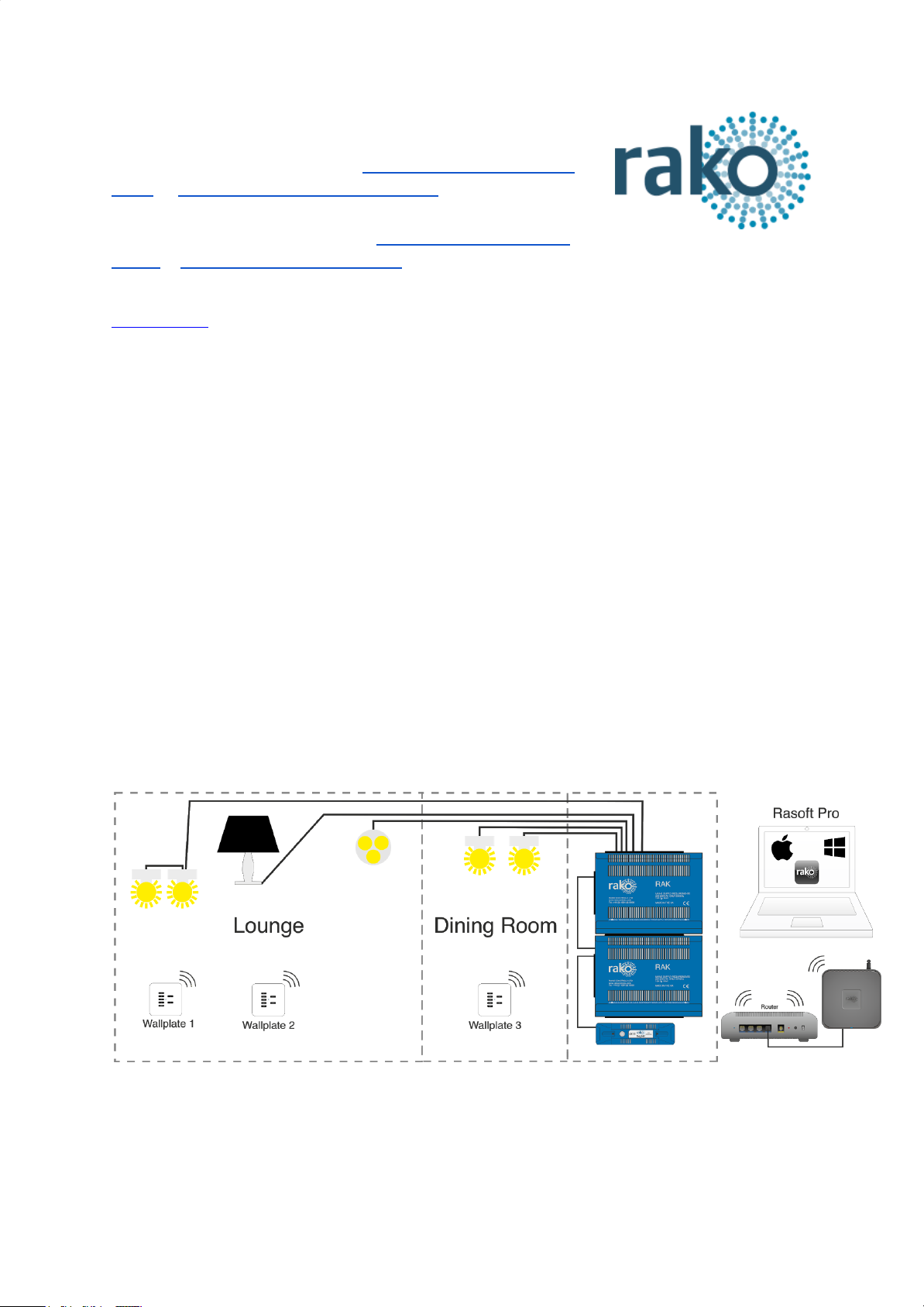
Wireless system (RxLINK):
The RxLINK is used to integrate the RAK(s) into the wireless system and can support a total
of 16 circuits. For example two RAK8s or one RAK8 and two RAK4s.
RAK4-T Manual Version 2.3.9
Page 2
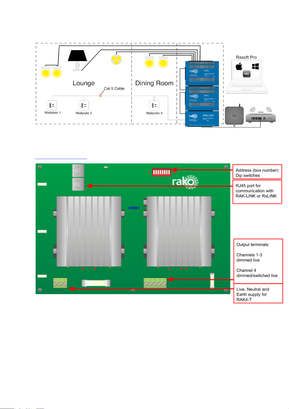
Wired system (RAK-LINK):
The RAK-LINK is used to integrate the RAK(s) into the Rako Wired Network and can support
a total of 32 circuits. For example 4 RAK8s or 3 RAK8s and 2 RAK4s.
The circuit board:
RAK4-T Manual Version 2.3.9
Page 3
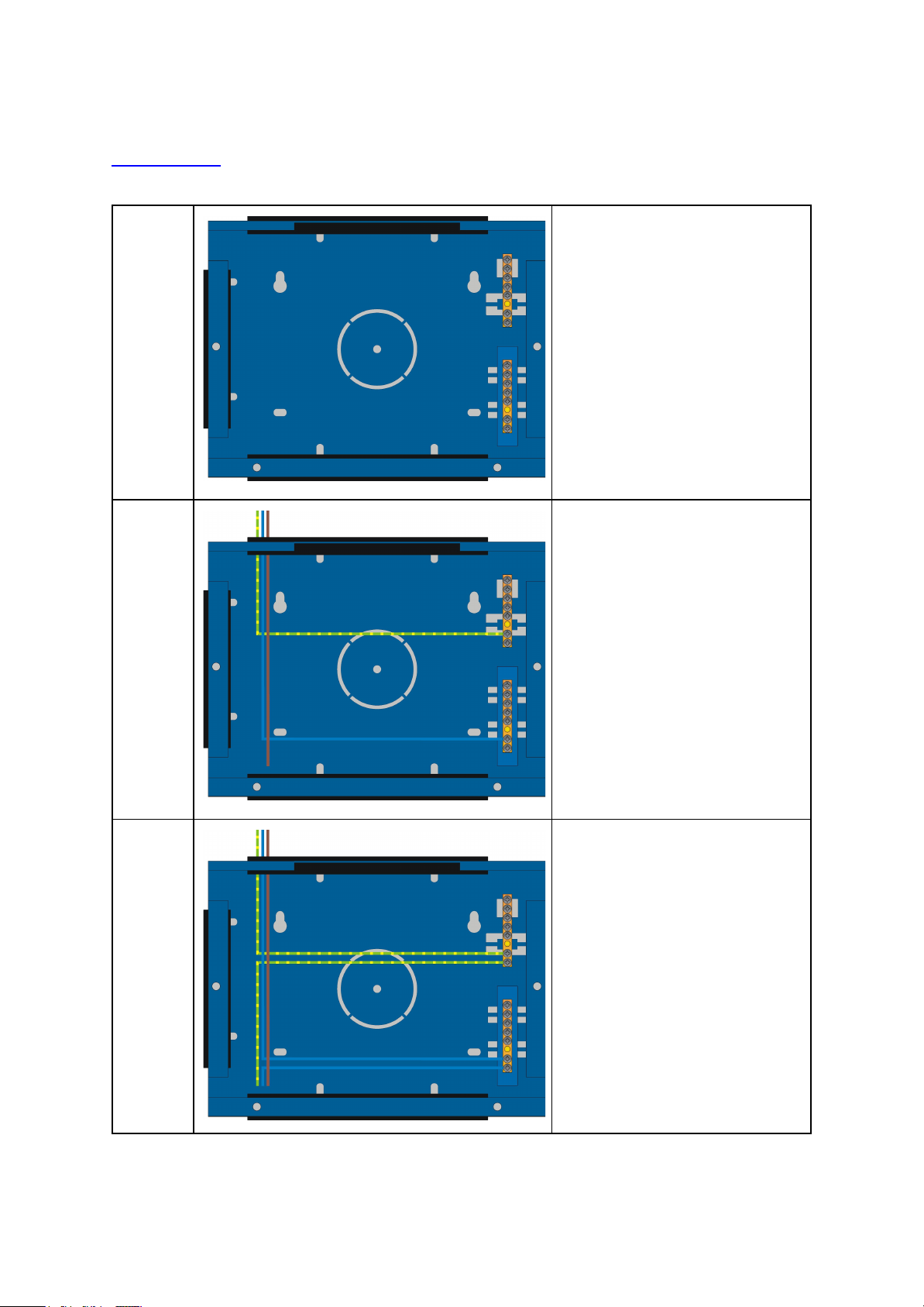
Installation:
POWER SHOULD BE ISOLATED THROUGHOUT THE INSTALLATION PROCESS
Step 1
Secure metal box housing to
wall or secure mounting
position.
The RAK system relies on
being vertically mounted to
allow the ventilation system to
work properly.
Step 2
Bring a separate 10A protected
supply to each RAK case.
Connect the Neutral and Earth
to the busbars as shown.
Bring the Live to the front of the
metalwork ready for connection
to the circuit board.
Step 3
Bring a single Neutral and Earth
from the busbars to the front of
the metalwork.
Prepare screws on either side
of metalwork ready to hold the
circuit board. They should be
present and screwed loosely in
to the case.
RAK4-T Manual Version 2.3.9
Page 4

Step 4
Place the circuit board on the
two screws on either side of the
metalwork.
Do not screw down at this stage
as the busbars need to be
accessible for Neutral/Earth
connections of lighting circuits.
Connect Live, Neutral, Earth for
board supply as indicated.
Step 5
Begin connecting lighting loads.
Connect Neutral and Earth to
appropriate busbars in the back
of the casing.
Make Live connections to the 5
way terminal block as shown or
for as many circuits as used.
Step 6
Insert the RJ45 cable from the
RAK-LINK/RxLINK into the port
on the RAK and from there
another RJ45 cable to each
RAK in the “stack”.
Screw down the circuit board to
secure it to the case and fit lid
to complete installation.
RAK4-T Manual Version 2.3.9
 Loading...