

Page 1
RAK4-R Instruction Manual
For programming information: Wireless RAK Programming
guide or Wired system Programming Guide
For general system information: Wireless RAK Application
Sheet or Wired RAK Application Sheet
Overview
The Rako RAK4-R is a four channel controller which can be used to operate most types of
Curtain, Blinds and Screen motors.
Each of the four outputs comprise two uncommitted volt-free relays. The relays can be wired
or switched to suit the specific motor connected to them. The RAK4-R provides aux Live
outputs that can be used to drive AC motors.
RAK4s, combined with a Link device (Rx-LINK or RAK-LINK) can either be used as a single
4 channel unit or formed into a “stack”. RAK4s can be also be used in combined stacks with
RAK8-MB units on the same Link device.
Before commencing installation of a Rako product first read this instruction manual carefully. Rako Controls Ltd.
accepts no responsibility for any damage or injury caused by incorrect installation of a Rako product. Installation
should only be carried out by a qualified electrician. Always install RAK units in a well ventilated room, with a
minimum clearance of 50mm at the sides in the correct orientation i.e. vents top and bottom. Each RAK unit
must be earthed.
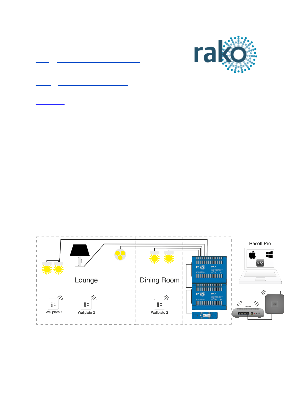
Wireless system (RxLink):
The RxLINK is used to integrate the RAK(s) into the wireless system and can support a total
of 16 circuits. For example two RAK8s or one RAK8 and two RAK4s.
RAK4-R Manual Version 2.3.8
Page 2
Wired system (RAK-LINK):
The RAK-LINK is used to integrate the RAK(s) into the Rako Wired Network and can support
a total of 32 circuits. For example 4 RAK8s or 3 RAK8s and 2 RAK4s.
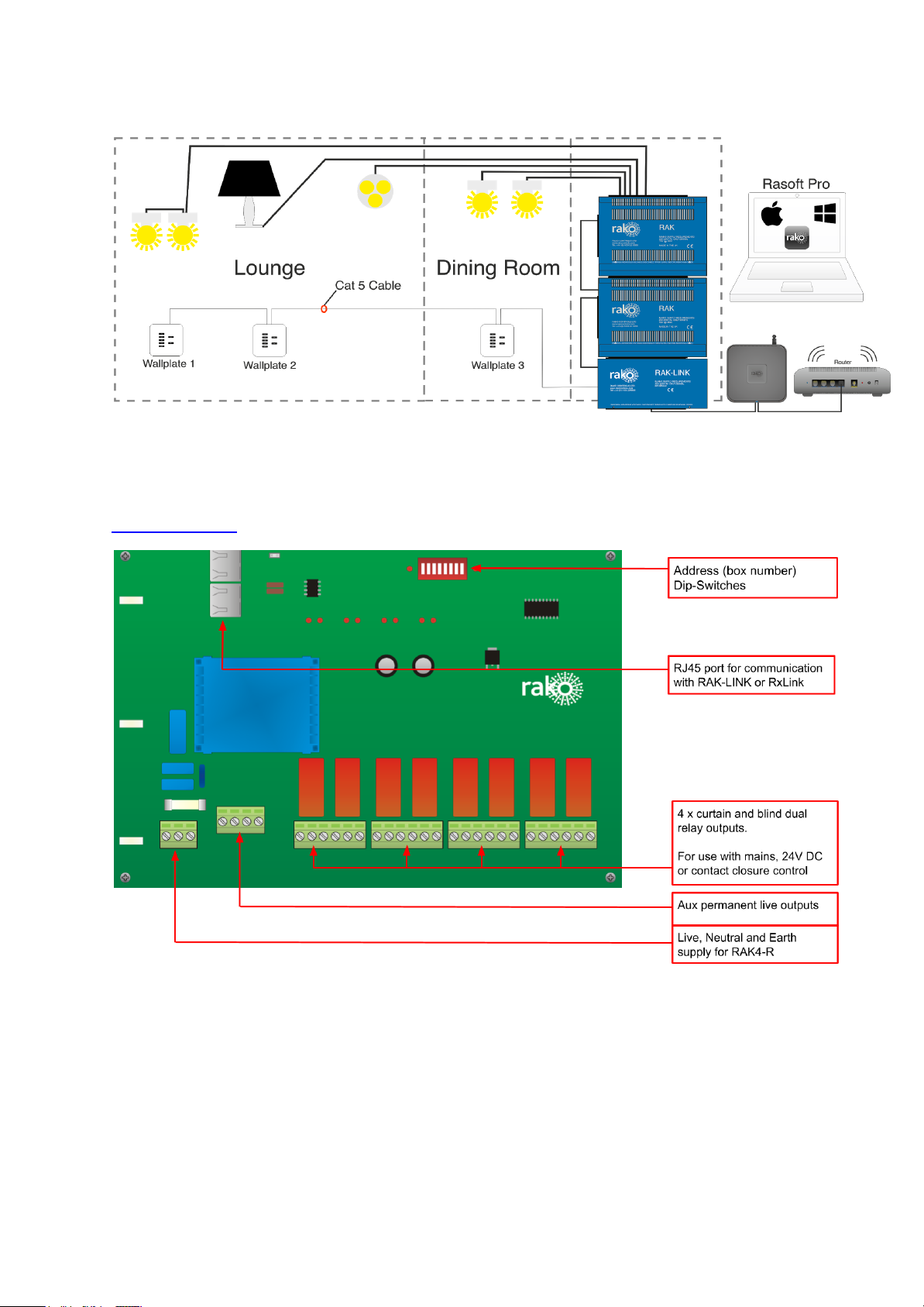
Circuit Board
RAK4-R Manual Version 2.3.8
Page 3

Installation
POWER SHOULD BE ISOLATED THROUGHOUT THE INSTALLATION PROCESS
Step 1
Secure metal box housing to
wall or secure mounting
position.
The RAK4 system relies on
being vertically mounted to
allow the ventilation system to
work properly.
Step 2
Bring a separate 10A MCB
protected supply to each RAK
case.
Connect the Neutral and Earth
to the busbars as shown.
Bring the live to the front of the
metalwork ready for connection
to the circuit board.
Step 3
Bring a single Neutral and Earth
from the busbars to the front of
the metalwork.
Prepare screws of either side of
metalwork ready to hold the
circuit board. They should be
present and screwed loosely in
to the case.
RAK4-R Manual Version 2.3.8
Page 4

Step 4
Insert the circuit board on to the
two screw on either side of the
metalwork.
Do not screw down at this stage
as the busbars need to be
accessible for Neutral/Earth
connections of curtain/blind
circuits.
Connect Live, Neutral, Earth for
board supply as indicated.
Step 5
Insert the RJ45 cable from the
RAK-LINK/RxLink into the port
on the RAK4-F.
See “Wiring for different motor
types” for load connections
Wiring for different motor types:
Mains switching
The RAK4-R is most commonly used with “mains switching blinds”. The six way terminal
block is fed with permanent mains and has two switched outputs. A three core and earth
cable should be run from the RAK4-R to the blind.
24V Polarity switching
The RAK4-R can also be used to control 24V polarity switching blinds. In this case a
separate 24V power supply is required and a two core cable should be run from the RAK4-R
to the blind.
Contact Closure
The RAK4-R can be used to provide a control signal to the blinds. In this case a 3 core cable
is run from the RAK4-R to the blind control box.
RAK4-R Manual Version 2.3.8
Page 5

Mains Blinds wiring:
Terminal
Mains
1
Permanent Mains
2
Relay A Output (Open)
3
Linked to 4
4
Linked to 3
5
Relay B Output (Close)
6
Not used
24V Blind wiring:
Terminal
24V
1
Relay A Output (Open)
2
+24V from PSU
3
0V from PSU
4
Relay B Output (Close)
5
+24V from PSU
6
0V from PSU
RAK4-R Manual Version 2.3.8
Page 6

Contact closure blind wiring diagram:
Terminal
Contact Closure
1
Common
2
Relay A Output (Open)
3
Not used
4
Common
5
Relay B Output (Close)
6
Not used
RAK4-R Manual Version 2.3.8
 Loading...