

Page 1
RAK4-F Instruction Manual
For programming information: Wireless RAK Programming guide
or Wired system Programming Guide
For general system information: Wireless RAK Application Sheet
or Wired RAK Application Sheet
Overview:
A four channel dimming RAK, designed to be wall mounted in an electrical cupboard. The
RAK4-F has four switched mains outputs and four “digital signal” outputs. These “digital
signal” outputs can be configured to control 0-10V, DLI and DSI fittings.
NB
DLI signals from the RAK4-F are broadcast only. For addressable DLI the RSR/WSR-DLI is required.
The RAK4-F has a maximum loading of 5A per channel and 10A for the entire unit.
RAK4s, combined with a Link device (RxLINK or RAK-LINK) can either be used as a single 4
channel unit or formed into a “stack”. RAK4s can be also be used in combined stacks with
RAK8-MB units on the same Link device.
Before commencing installation of a Rako product first read this instruction manual carefully. Rako Controls Ltd.
accepts no responsibility for any damage or injury caused by incorrect installation of a Rako product. Installation
should only be carried out by a qualified electrician. Always install RAK units in a well ventilated room, with a
minimum clearance of 50mm at the sides in the correct orientation i.e. vents top and bottom. Each RAK unit
must be earthed.
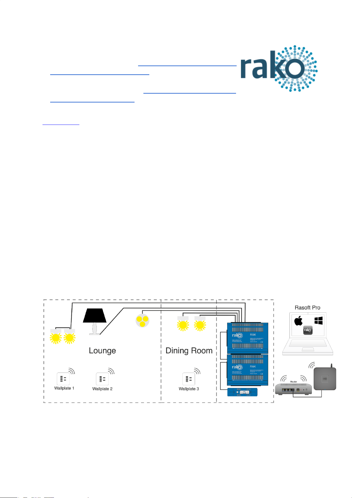
Wireless system (RxLINK):
The RxLINK is used to integrate the RAK(s) into the wireless system and can support a total
of 16 circuits. For example two RAK8s or one RAK8 and two RAK4s.
RAK4-F Manual Version 3.1.1
Page 2
Wired system (RAK-LINK):
The RAK-LINK is used to integrate the RAK(s) into the Rako Wired Network and can support
a total of 32 circuits. For example 4 RAK8s or 3 RAK8s and 2 RAK4s.
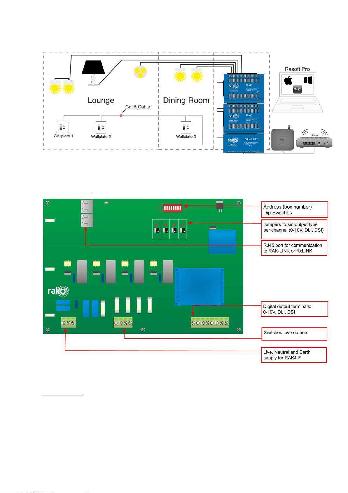
Circuit Board:
Installation:
POWER SHOULD BE ISOLATED THROUGHOUT THE INSTALLATION PROCESS
RAK4-F Manual Version 3.1.1
Page 3

Step 1
Secure metal box housing to
wall or secure mounting
position.
The RAK system relies on
being vertically mounted to
allow the ventilation system to
work properly.
Step 2
Bring a separate protected
supply to each RAK case.
Connect the Neutral and Earth
to the busbars as shown.
Bring the Live to the front of the
metalwork ready for connection
to the circuit board.
Step 3
Bring a single Neutral and Earth
from the busbars to the front of
the metalwork.
Prepare screws on either side
of metalwork ready to hold the
circuit board. They should be
present and screwed loosely
into the case.
RAK4-F Manual Version 3.1.1
Page 4

Step 4
Place the circuit board on the
two screws on either side of the
metalwork.
Do not screw down at this stage
as the busbars need to be
accessible for Neutral/Earth
connections of lighting circuits.
Connect Live, Neutral, Earth for
board supply as indicated.
Step 5
Begin connecting lighting loads.
Connect Neutral and Earth to
appropriate busbars in the back
of the casing.
Make Live connections to the 4
way terminal block as shown or
for as many circuits as used.
Make Digital Output
connections to the 8 way
terminal block as shown for as
many circuits as used.
Step 6
Insert the RJ45 cable from the
RAK-LINK/RxLINK into the port
on the RAK4-F.
Screw down the circuit board to
secure it ot the case and fit lid
to complete installation
Select Digital output type by
setting the jumpers on the
circuit board.
NB
See “Setting Digital Output Type”
section below.
RAK4-F Manual Version 3.1.1
Page 5

Setting Digital Output Type:
Each channel of RAK4-F can be configured for either 0-10V, DLI (broadcast) or DSI
operation. Default factory setting is 0-10V. The digital output type is edited by either setting
the jumpers on the circuit board or by using the software depending on the age of the
RAK4-F.
Issue C Boards (jumpers fitted)
When jumpers are fitted they MUST be used to set the output type, the method using
Rasoft Pro will not work.
The digital output type is set by using the jumpers on the circuit board. Output type can be
set separately for each channel of the RAK4-F. If all jumpers are removed then the RAK4-F
will default to 0-10V mode.
NB
For example in the picture above Channels 1, 2 and 3 are set to “0-10V” and Channel 4 is set to “DLI”.
Issue A/B Boards (no jumpers fitted)
For older board types the output setting is set via Rasoft Pro. Before setting the output type
the software must:
- Be connected to an appropriate programming device (Bridge or RAMPI)
- Have programmed the RAK4-F such that it has been assigned a Room and a
Channel.
Select “RAK-CIRCUIT” within the device editor and then edit the “Output Options” tab. Press
“Save and Upload” to upload this change to the RAK4-F.
RAK4-F Manual Version 3.1.1
 Loading...