

RAK RAK475 UART Instruction Manual

1
RAK475 Instruction manual
RAK475 UART WiFi Module
Instruction Manual V1.1
Shenzhen Rakwireless Technology Co., Ltd.
www.rakwireless.com
info@rakwireless.com
© RAK copyright. All rights reserved.
Companies and product names referred in
the instruction belong to trademarks of
their respective owners.
Any part of this document may not be
reproduced, and may not be stored in any
retrieval system, or delivered without RAK's
written permission.
The document will be updated without
prior notice.
Copyright © Shenzhen Rakwireless Technology Co., Ltd
ETDX1602241830

2
RAK475 Instruction manual
Content
1. Rapid usage.................................................................................................................................... 4
1.1 Introduction to the development board..............................................................................4
1.2 The method for the module to reset to Factory Defaults................................................. 5
1.3 Inspection prior to powering on
1.4 The status after powering on.............................................................................................. 6
1.5 Transparent transmission data test.....................................................................................8
2. Function features
.........................................................................................................................
2.1 Overview........................................................................................................................... 10
2.2 Application fields..............................................................................................................10
2.3 Product features.................................................................................................................10
3. Instruction encyclopedia............................................................................................................. 12
3.1 Network configuration method........................................................................................12
3.2 Web page configuration....................................................................................................13
3.2.1 Module status
........................................................................................................
3.2.2 Network settings................................................................................................... 15
3.2.3 Communication settings....................................................................................... 19
3.2.4 Certificate management........................................................................................21
3.2.5 Equipment management....................................................................................... 22
3.2.6 Firmware upgrading..............................................................................................22
3.3 App wireless configuration.............................................................................................. 23
3.4 Instant configuration
.........................................................................................................
4. Aided AT commands................................................................................................................... 26
4.1 Basic flow chart................................................................................................................ 26
4.2 AT command set
................................................................................................................
4.3 Command Format............................................................................................................. 28
4.4 Enter into aided commands..............................................................................................29
4.5 Module management instruction..................................................................................... 31
4.5.1 Open ASCII display
4.5.2 Query the module’s MAC address.......................................................................31
4.5.3 Enter into the transparent transmission mode.....................................................32
4.5.4 Query the software version.................................................................................. 33
4.5.5 Reset to restart the module
4.5.6 Reset to Factory Defaults..................................................................................... 35
4.6 Parameter configuration instruction................................................................................ 36
4.6.1 Write user configuration
4.6.2 Read the user configuration................................................................................. 37
4.6.3 Reproduce the user configuration........................................................................38
4.6.4 Read Factory Defaults.......................................................................................... 39
4.6.5 Read Factory Defaults
4.7 AP STA operating instruction.......................................................................................... 41
4.7.1 Query the connection status of STA....................................................................41
4.7.2 Query the connection status of AP
4.7.3 The wireless signal intensity of STA...................................................................43
4.7.4 Scan the wireless network.................................................................................... 44
4.7.5 Get the wireless network...................................................................................... 46
4.7.6 EasyConfig networking........................................................................................48
4.7.7 WPS networking................................................................................................... 49
4.7.8 Query IP inFormation...........................................................................................50
.........................................................................................
..............................................................................................
...................................................................................
.......................................................................................
..........................................................................................
......................................................................
Copyright © Shenzhen Rakwireless Technology Co., Ltd
ETDX1602241830
10
13
24
27
31
34
36
40
42
6

3
RAK475 Instruction manual
4.7.9 Ping command.......................................................................................................51
4.7.10 Query the connected network inFormation...................................................... 52
4.8 Instruction for receiving and sending the data................................................................53
4.8.1 Send data
................................................................................................................
53
4.8.2 Receive data.......................................................................................................... 54
4.9 Read and write NVM data................................................................................................56
4.9.1 Write data to NVM............................................................................................... 56
4.9.2 Read NVM data.....................................................................................................57
4.10 Command for setting the certificate..............................................................................58
4.10.1 Set ssl security certificate...................................................................................58
4.11 InFormation storage commands for the user networking list
......................................
60
4.11.1 Read the number of current list..........................................................................60
4.11.2 Read the networking inFormation in the indicated lists.................................. 60
4.11.3 Write the networking inFormation to the indicated lists
..................................
62
4.11.4 Delete the networking inFormation in the indicated lists................................63
4.12 Upgrading of serial port firm ware................................................................................64
4.12.1 Enter into the upgrading mode.......................................................................... 64
5. Appendix-configuration parameter encyclopedia
.....................................................................
66
6. Version..........................................................................................................................................71
Copyright © Shenzhen Rakwireless Technology Co., Ltd
ETDX1602241830
4
RAK475 Instruction manual
1. Rapid usage
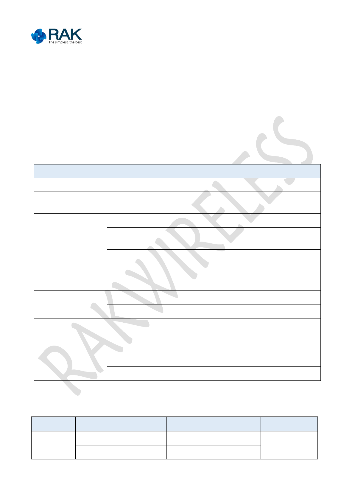
1.1 Introduction to the development board
RAK475 serial port transparent transmission module focuses on transparent
Function
Name
Description
Module
U3
RAK475 transparent transmission WIFI module
External Interface
Micro USB
Input power supplied DC5V, communication interface
of USB to serial port
Key
Reset
Module reset key
WPS/MODE
WPS function is to instantly configured to the network
(match with the router’s WPS)
Default
1. Press the “greater than 3 seconds” module to
recover to the Factory Defaults parameters
2. Press the “less than 1 second”, instantly configure
the easyconfig mode
Pin
P2
UART and 232 interface
P6
Reset, Link and other pins
Power Consumption
pin
J1
Power consumption measurement interface
LED Indicators
POWER
Power Lamp
STATUS
Start Running Indicator Lamp
LINK
Network Indicator Lamp
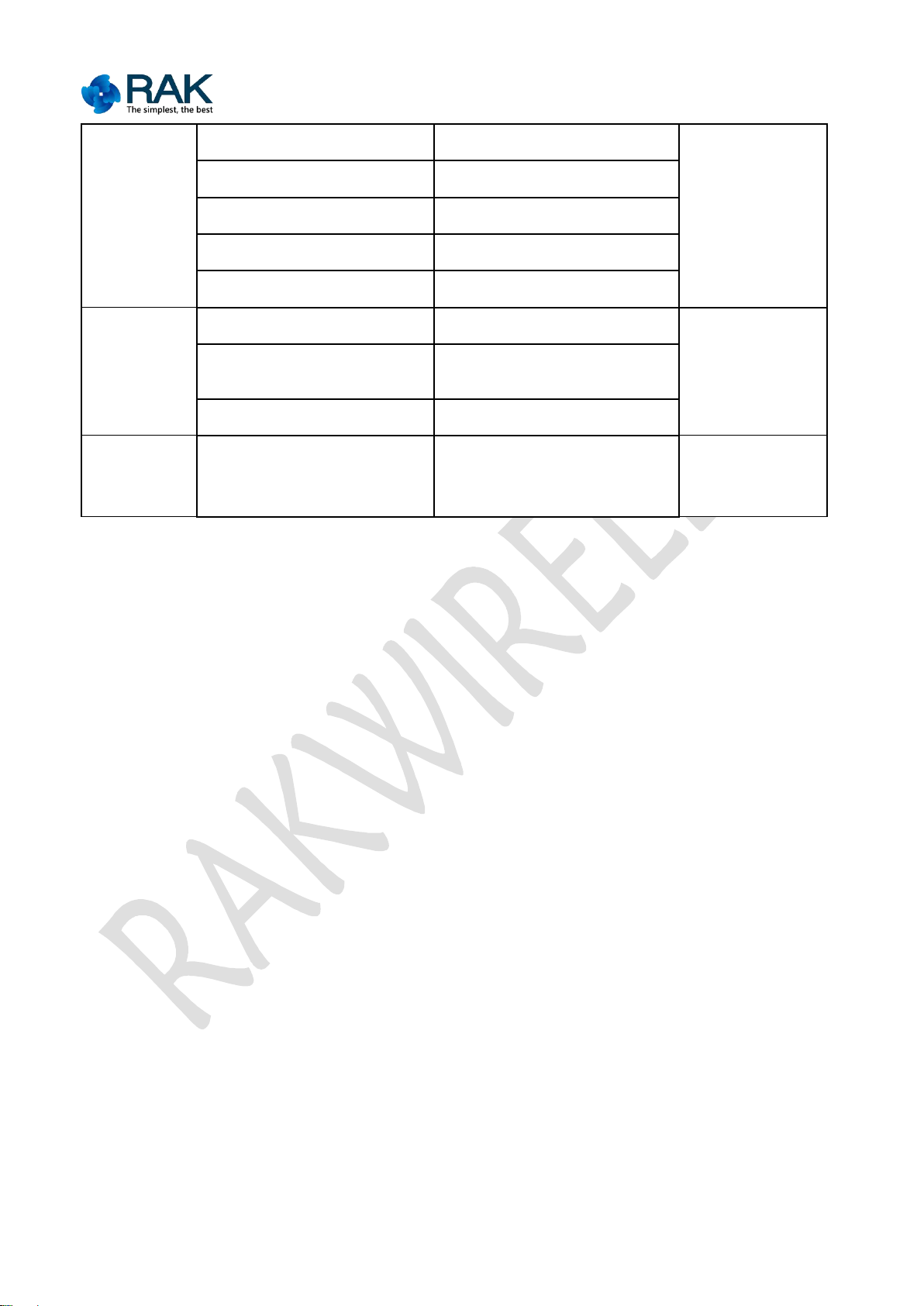
Status
Link
Status
Function
Instant configuration
Flash interval of 200ms
Normally on
Upgrading of hard wares
Flash interval of 50ms
transmission supported by AT Command; it has the advantages of simple operation
and rich functions and can meet the requirements of various kinds of customers.
First, let's see the usage of RAK475 evaluation suits.
Table 1-1: Development board source
Table 1-2: LED Definition
Copyright © Shenzhen Rakwireless Technology Co., Ltd
ETDX1602241830
5
RAK475 Instruction manual
Note:
“Status” light is a start light, which is in the normally on status after the
After pressing the instant configuration key for less than 1 second, “Link” light
After pressing the recovering Factory Defaults key for more than 3 seconds,
Coexistence of AP and SAT mode, the indicator lamps indicate jointly
1.2 The method for the module to reset to Factory Defaults
STA Mode
Unconnected
Normally off
Normally on
Connecting to the network
Flash interval of 1 second
Getting IP
Flash interval of 2 seconds
The network is connected
Normally on
Socket event
Flash for three times
AP mode
AP is not established
Normally off
Normally on
AP is established, and not
connected
Periodically on and off in 1
second
STA is connected
Normally on
Factory
Defaults
Mode
Recovering Factory Defaults
takes effect
Periodically on and off in
500ms
Periodically on
and off in 500ms
module starts regularly.
flashes until the configuration is successful or of timeout.
“Link” and “Status” are on and off at the same time, and automatically reset
after 3 seconds.
There is a “Default” key on the development board, which is used to reset to
Factory Defaults for the module when the configuration is made by mistakes or the
current configuration parameters are forgotten:
Press the “Default” key for over 3 seconds, the indicator lamp “Link” and
“Status” are on and off at the same time, at this time, loose the “Default” key for
3 seconds, the module will reset to the Factory Defaults mode (establish AP by
default, and the customer can modify the defaults parameters).
Copyright © Shenzhen Rakwireless Technology Co., Ltd
ETDX1602241830
6
RAK475 Instruction manual
1.3 Inspection prior to powering on
The evaluation suits mainly include: antenna of Micro USB line, development board,
1.4 The status after powering on
1. Double click to join the network (at this time, “Link” will be normally on), wait
IPEX connector interface. If the module is external antenna module, please plug in
the antenna. Connect the module’s serial port and computer’s serial port (the USB
to serial port of the computer).
Normal phenomenon
After the module is powering on, the power indicator lamp (power lamp) lights on,
next, the “Status” light is on (the “Status” pins output the low level), it shows
that the module starts regularly.
If the “status” light is not on after powering on, please try to press the “Reset”
key. If the light is always off, please contact the After-Sale Service.
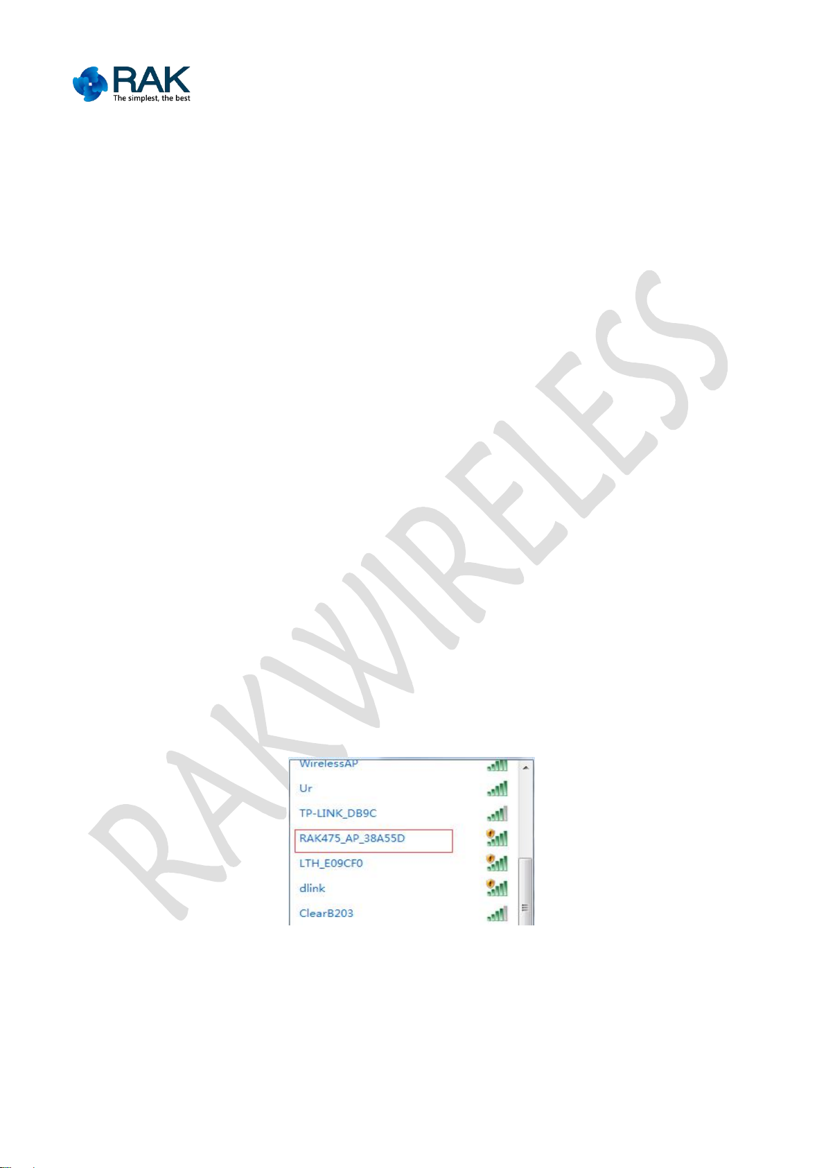
Under the Factory Defaults mode of the module, an open AP network will be
established after powering on, with the name of RAK475_AP_XXXXXX (XXXXXX is the
rear six digits of the module's MAC address), IP address of 192.168.7.1, default
opening of DHCPSever (the Factory Defaults can be modified). After the “Status”
light is on, open the computer's wireless network, RAK475_AP_XXXXXX will be found
in the wireless list, as shown below:
Figure 1-1: Factory Defaults AP scanning
for well distributed IP address. Open the browser and input the gate address of
the module-192.168.7.1, the web page pops up an authentication interface,
Copyright © Shenzhen Rakwireless Technology Co., Ltd
ETDX1602241830

7
RAK475 Instruction manual
inputs the authenticated user name and PIN (“admin” by default).
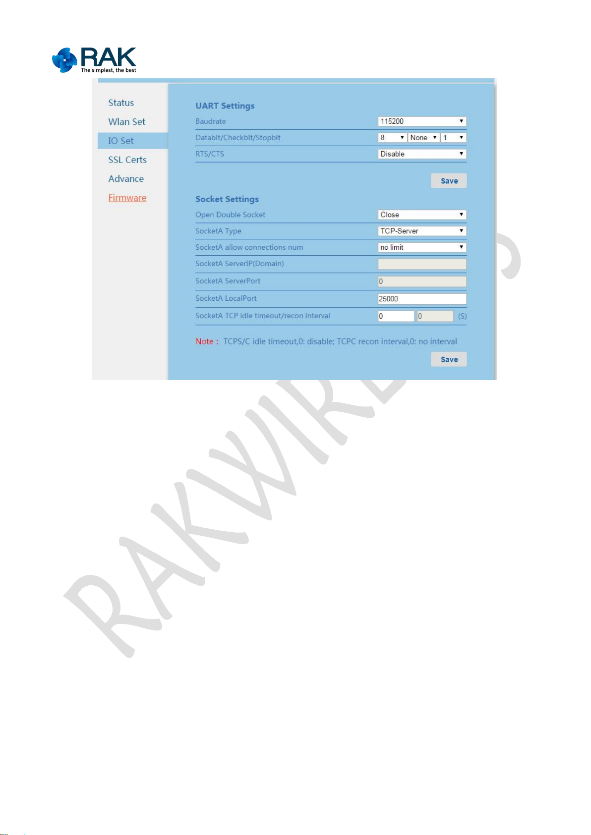
2. You can see the WEBSever interface with the built-in module.
3. The serial port communication and socket communication settings of the
Figure 1-2: WEB webpage authentication
Figure 1-3: WEB webpage- module status
module by default are as shown below:
Copyright © Shenzhen Rakwireless Technology Co., Ltd
ETDX1602241830
8
RAK475 Instruction manual
Figure 1-4: Default IO communication page
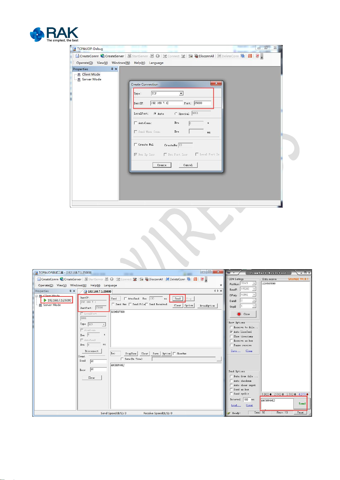
1.5 Transparent transmission data test
1. Open the serial port tools, select the COM port connected to the module. The
default baud rate is 115200, data bit is 8, stop bit is 1, with no parity, no flow
control. Open network debugging tools (TCP/UDP tool), establish TCP client to
connect the IP and port of the other party (the default IP of the module is
192.168.7.1, the server port is 25000).
Copyright © Shenzhen Rakwireless Technology Co., Ltd
ETDX1602241830
9
RAK475 Instruction manual
Figure 1-5: Establish TCP Client
2. After TCP is connected, the data can be sent to each other. At this time, the serial
port of the module is changed into the virtual serial port of the network, and the
serial port data and network data is interconnected.
Figure 1-6: Factory Defaults mode transparent transmission test
Copyright © Shenzhen Rakwireless Technology Co., Ltd
ETDX1602241830

10
RAK475 Instruction manual
2. Function features
2.1 Overview
RAK475 module is an ultra-low power consumption WIFI module which fully
2.2 Application fields
Portable products
Household appliance
Industrial sensor
POS terminal
Building automation
Logistics and freight management
Household security and automation
Medical field, for example, patients monitoring, medical diagnosis
Measurement (parking meter, metering instrument, ammeter and the like)
2.3 Product features
Meet 802.11b/g/n wireless protocol
Built in TCP/IP protocol stack
Support OPEN, WEP, and WPA/WPA2-PSK encryption
Support SoftAP, Station, and coexistence of SoftAP and Station mode.
supports IEEE802.11b/g/n wireless protocol, and has the advantages of small
packaging and easy usage. The module is completely serial port transparent
transmission module, inside which integrates TCP/IP protocol stack and driver, the
usage is convenient, after simple configuration, it can be used regularly, the module
connects the physical serial port and network, and access the connected equipment
into the network.
RAK475 module has the advantages of stable perFormatnces, ultra-low power
consumption, flexible usages, it can meet various customer’s requirements, provide
various test reports, allow the customer to quickly start so as to reduce the research
and development period.
RAK475 module also provides various kinds of customized services, such as user
WEB page, production configuration tools, mobile phone APP and the like.
Copyright © Shenzhen Rakwireless Technology Co., Ltd
ETDX1602241830

11
RAK475 Instruction manual
Support TCP, UDP, SSL and other communication protocols
Support DHCP SERVER、DHCP CLIENT
Support giving priority to the transparent transmission supplemented by AT
commands
Support the UART communication with the data flow, the maximum baud rate is
Support various configuration tools, and the module can be configured in one
Support the wireless upgrading module firm ware
Board antenna or U.FL antenna connector
Working voltage: 3.3V
Support the automatic power saving work mode
Meet FCC, RoHs and CE authentication
921600bps
step
Copyright © Shenzhen Rakwireless Technology Co., Ltd
ETDX1602241830

12
RAK475 Instruction manual
3. Instruction encyclopedia
3.1 Network configuration method
The transparent transmission module aims at data communication in the end, WIFI
Access the Web server with the built-in module via the browser to carry out
Use WPS function to connect with the router rapidly
Use EasyConfig function to realize the connection with the router
communication is carried out under the preconditions of parameter configuration,
the important thing is the network configuration (network name, PIN and IP address)
and which kind of communication protocol socket set (TCP, UDP and SSL security) to
use. The module defines the following two concepts for the parameters.
At first, the module defines two parts, namely, Factory Defaults parameters and user
parameters.
Factory Defaults parameters: the module maintains the parameters of the initial
status when it is not regularly used (generally acts as AP access point), at this time,
the module has independent network name, fixed IP address, etc. The Factory
Defaults mode ensures the recovery of the module, so as to avoid the problems
caused by users’ configuration mistakes. (Factory Defaults parameters can be
modified by customers)
User parameters: when the module was regularly configured, the module will enable
a new configuration to be user parameters as will be automatically loaded when the
module resets, the user parameters are the configuration of actual application of
customers. (can write once)
In order to transfer from the Factory Defaults mode to the user mode easily, the
transparent transmission module provides four kinds of flexible configuration
methods to connect to the user’s router:
parameters modification
Copyright © Shenzhen Rakwireless Technology Co., Ltd
ETDX1602241830

13
RAK475 Instruction manual
The module supports the coexistence of AP and STA mode, i.e. users can not only
3.2 Web page configuration
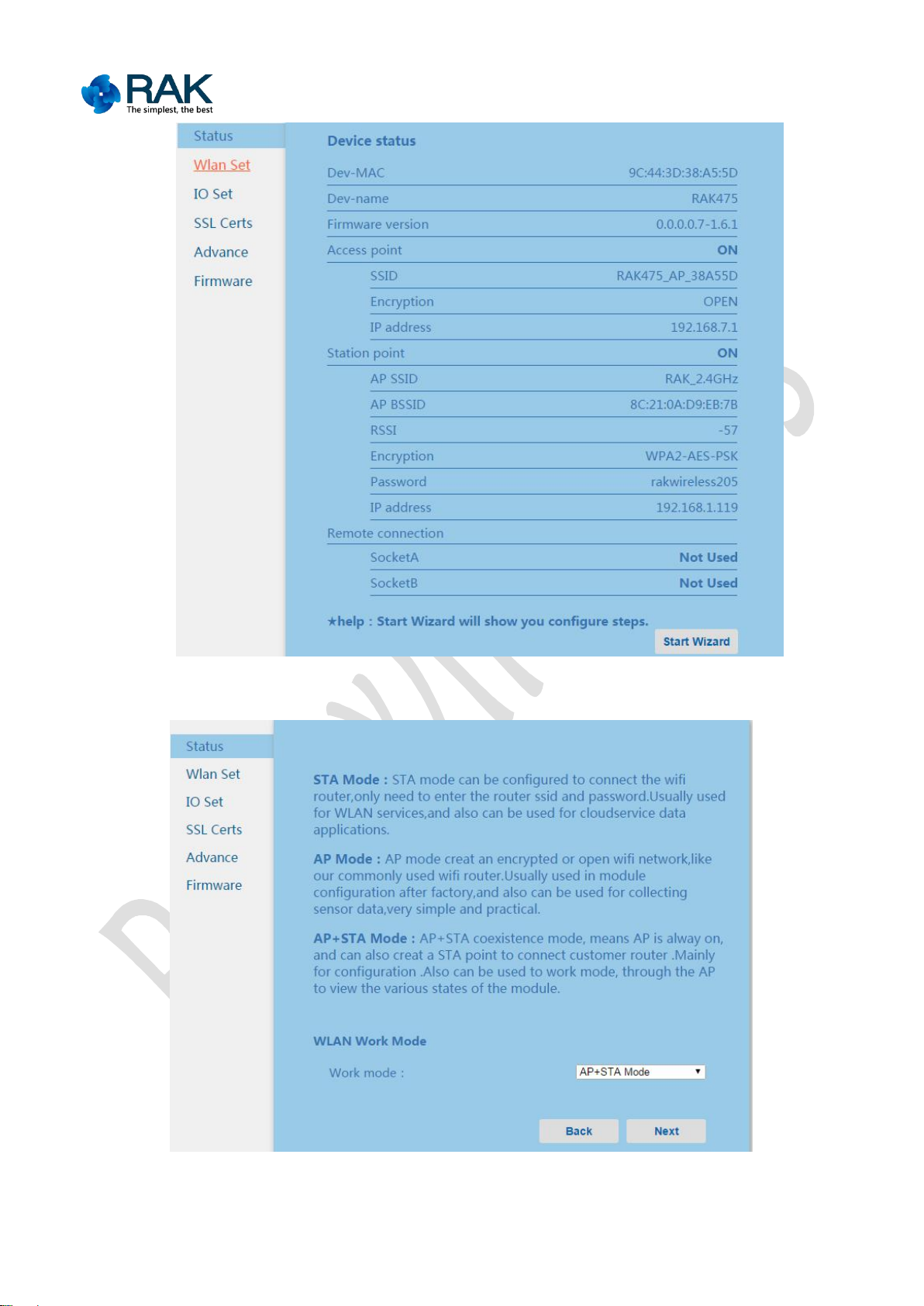
3.2.1 Module status
connect the module to the router (Internet), but also access and look up the module
and the like in the local net via the existing AP network, so as to be greatly
convenient for users and enhance the user's experiences.
After the module establishes AP or is added to the router, input the module's IP
address in the browser’s address column, then you can access. Under the AP mode,
IP address is gate address by default, for example, 192.168.7.1.Under the STA mode,
add the router, if IP address is automatically gotten, the module can get the address
from the home page's status bar via the coexisting AP, it can access WEB server as
well.
The module’s related inFormation is shown in the module’s status, for example,
the module’s MAC address, module name, software version; parameters in the AP
mode and STA mode.
Remote connection status means whether the module is successfully connected to
the server’s state inFormation when the two-way socket connection of the module
acts as a TCP client or SSL client.
The wizard button at the bottom of the page can be configured to navigate, so as to
help customers to complete the required configuration in turn. The following
configurations refer to the network settings section.
Copyright © Shenzhen Rakwireless Technology Co., Ltd
ETDX1602241830
14
RAK475 Instruction manual
Figure 3-1 Module status page
Figure 3-2 Module navigation page
Copyright © Shenzhen Rakwireless Technology Co., Ltd
ETDX1602241830

15
RAK475 Instruction manual
3.2.2 Network settings
WLAN settings are divided into: the choice of the work mode, AP parameters and
WLAN mode: AP, STA and AP+STA mode.
AP mode: AP mode settings produce an encrypted WIFI wireless network, which
STA mode: STA mode can be configured to add the home wireless router, the
AP +STA mode: coexistence means that when there is a AP hot spot, the module
AP SSID: The name length of AP is less than 32 bit.
whether to broadcast or not: You can select to open or close AP broadcast,
maximum STA connection number: 1 to 3 can be selected, if you don’t care,
STA parameter settings.
is similar to the commonly used wireless router. It is mainly used in the Factory
Defaults configuration of the module, and can also be used for data acquisition
points with the advantages of simple and practical.
name and password of the router can be filled in for general settings, select
DHCP. It is mainly used in local area network service, and can also carry out the
remote data application.
can also act as STA mode to connect to the router. It is mainly used for network
configuration and the actual work mode, and can see the status of the module,
etc. via the regular AP hot spot.
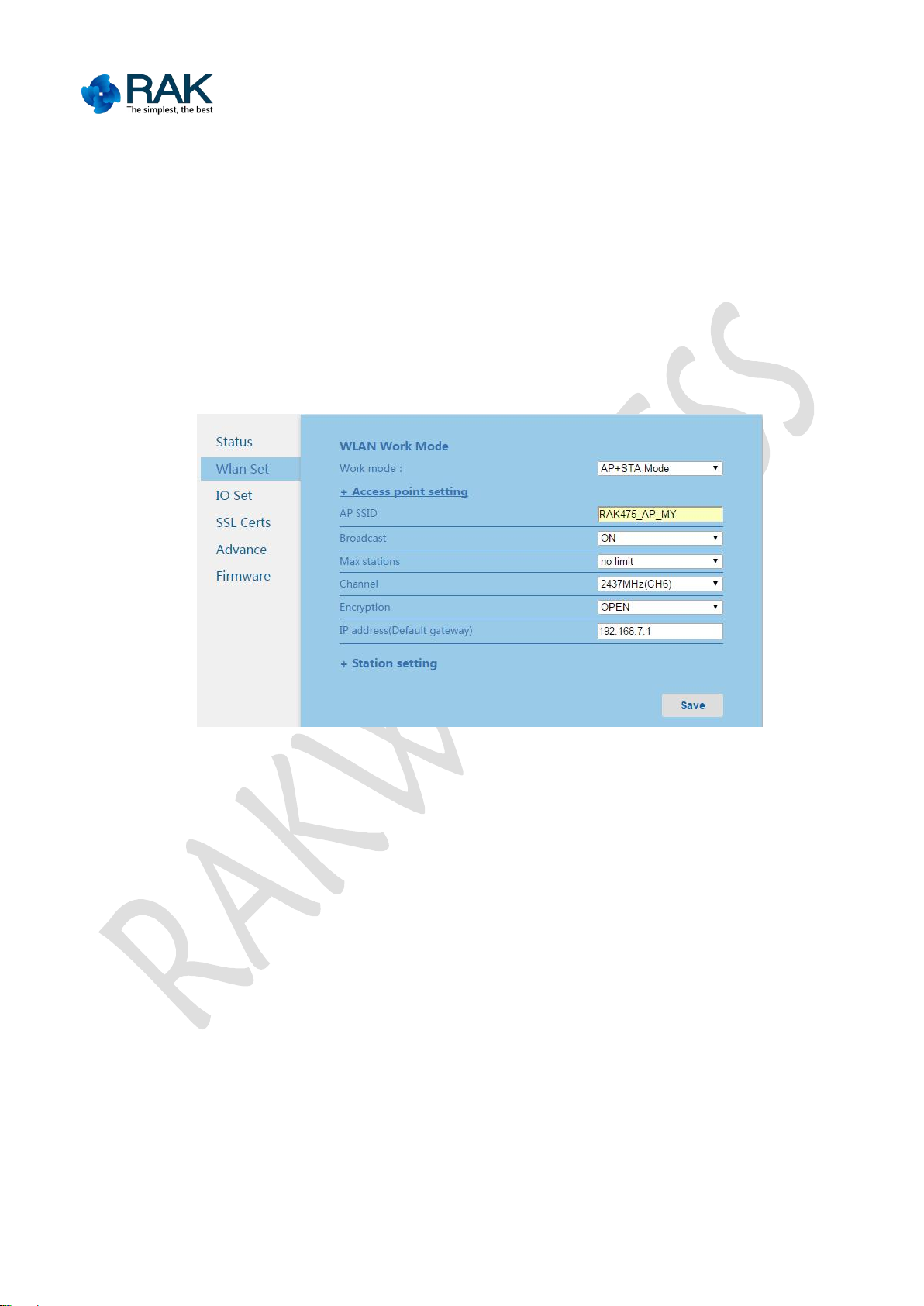
AP configurations:
closing AP broadcast can hide and increase the safety.
you may select unlimited, the maximum number (3 by default) can be set in the
module.
Copyright © Shenzhen Rakwireless Technology Co., Ltd
ETDX1602241830
16
RAK475 Instruction manual
Establish the channel: 1-13 can be selected, and you can select automation,
automatically select inside the module.
whether to encrypt or not: open, the encryption can be selected.
PIN: The length is less than 32 bit
IP address: Set the gate address of AP mode
Router SSID: The name length of the router is less than 32 bit.
Figure 3-3 Parameters page of the module AP
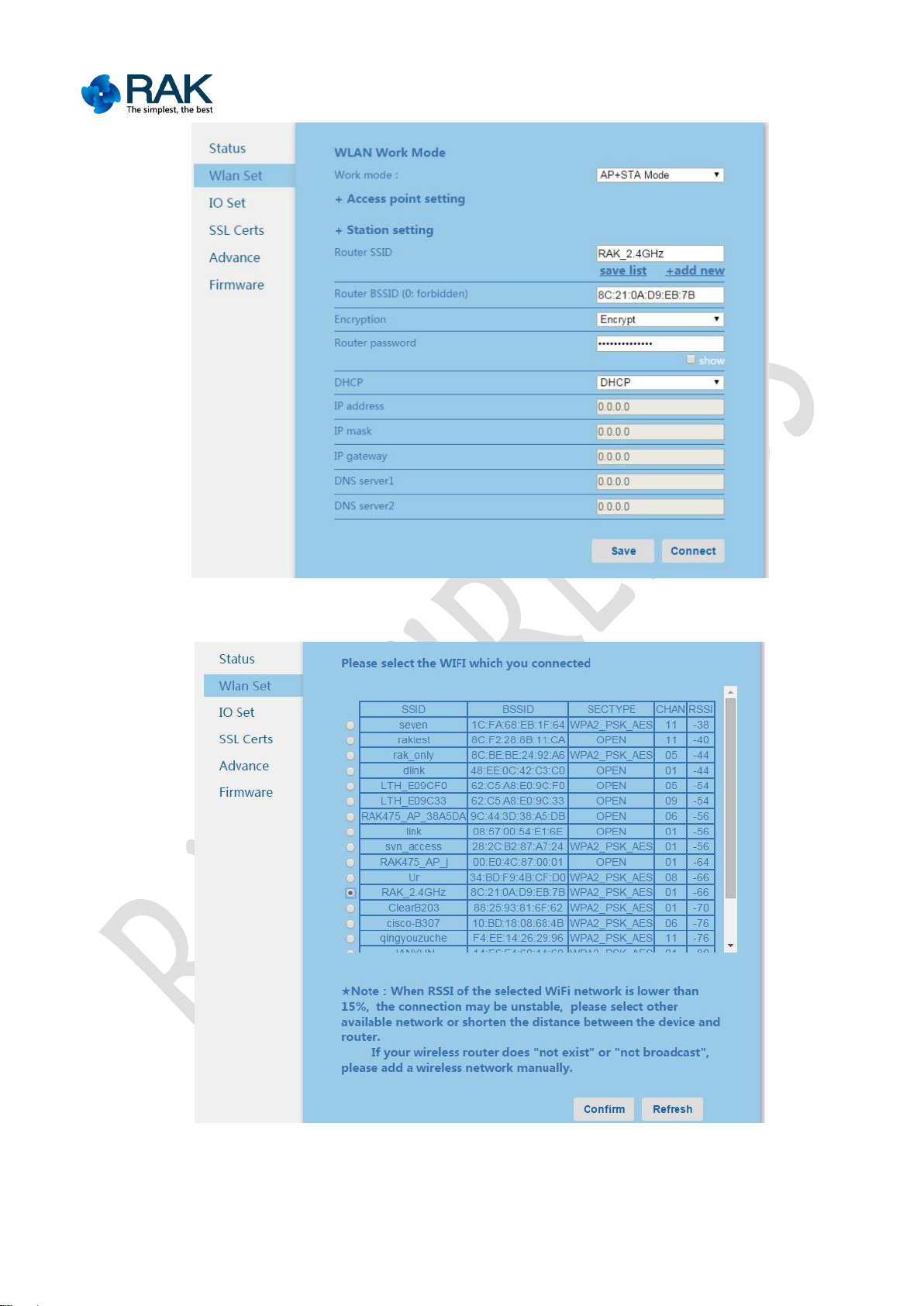
STA configurations:
Click “add network”, you can select router name to connect from the scanning list
sent back by the module, click "OK", then the web page will automatically fill in the
selected router name, if the router is encrypted, the prompt box will pop up to
prompt to input the password. You can manually enter the name from the router if
the router to add is hidden or not scanned.
Click "connected list", you can manage the list of connected networks, remove the
network that does not need to be used or no longer exists. This function can save the
Copyright © Shenzhen Rakwireless Technology Co., Ltd
ETDX1602241830

17
RAK475 Instruction manual
configuration of 5 sets of recently connected routers, after enabling the function, the
Router BSSID: The MAC address of the router is the only parameter to confirm
Whether to encrypt or not: open, the encryption can be selected.
Route encryption: The length is less than 32
DHCP option:You can select DHCP settings or static settings, namely, manually
IP address: The address which has the same network segment with the router
IP mask: It is the same with the router parameters
IP gate: It has the same parameters with the router; most of them are IP
Address of DNS server 1: gate address by default
Address of DNS server 2: it can fill in known DNS server address
module will firstly connect the router connected last time, if the router connection is
not successful, and the module will use the other routers in the list to try to connect.
If the connection fails, repeat the above mentioned connection. This feature is not
opened by default, it can be enabled via setting the "userlist_en" in FuncBitMap to
look the appendix - configuration parameters encyclopedia for details.
the router, which is used to differentiate the same router name, if you do not
specify the same router or not to use, it can be ignored, fill in 0.
input IP address
can be selected from the static IP distribution area of the router in the static
setting.
addresses of the router.
Copyright © Shenzhen Rakwireless Technology Co., Ltd
ETDX1602241830
18
RAK475 Instruction manual
Figure 3-4 Parameters page of the module STA
Figure 3-5 Module STA adds the network page
Copyright © Shenzhen Rakwireless Technology Co., Ltd
ETDX1602241830

19
RAK475 Instruction manual
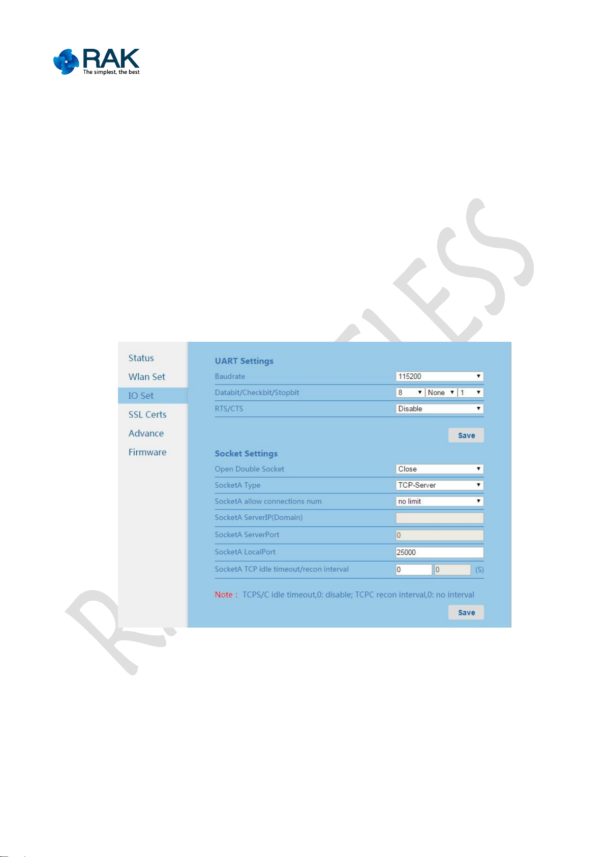
3.2.3 Communication settings
Communication settings includes: UART parameter settings and socket parameter
settings.
UART parameters configuration
The parameter settings of the serial port includes serial port baud rate, data bit,
check bit and stop bit, settings of the flow control. Serial port’s free split interval is
10ms, if the timeout for the byte received from the serial port is 10ms, the serial port
data with the interval greater than 10ms will be split and sent to the network.
Set the Socket parameters
Socket communication settings, socket parameter settings mainly include the
communication socket type, the server’s IP address, port number, the local
server’s port number, TCP timeout and other parameters.
The module supports two communication Sockets, SocketA can act as one of the five
secure connections, namely, the TCP server, TCP client, UDP server, UDP client,
TLS/SSL secure connection, SocketB does not support a secure connection.
While using the same serial port communication, add two bytes tips to the
communication data, "S0" indicates the transceiver data of SocketA, "S1" indicates
the transceiver data of SocketB.
IP or domain name of the server can be filled with a fixed IP address or domain name
length of less than 42 characters.
The number of connections that Local server supports can set the number of clients
connected to the local server, 1-3 can be selected, if you select unlimited, then the
default maximum value is 4. When there are multiple connections, the module
communication will realize one-to-many communication, the data received from the
module serial port will be forwarded to the connected multiple client, take care that
Copyright © Shenzhen Rakwireless Technology Co., Ltd
ETDX1602241830
20
RAK475 Instruction manual
the data of multiple client will be in turn sent from the serial port.
TCP idle timeout parameter indicates that if the TCP connection has not data
communication in the set time, the module will take the initiative to close the TCP
connection at first and then carry out connection again. This parameter ensures that
when the TCP connection is abnormally disconnected, the module can be
automatically restored. The time range of the parameter is 1 to 600 seconds.
TCP reconnection interval settings can set delay time for the second connection after
TCPC connection is off, the user can get a balance in terms of perFormatnce and
power consumption.
Figure 3-6 Communication settings page
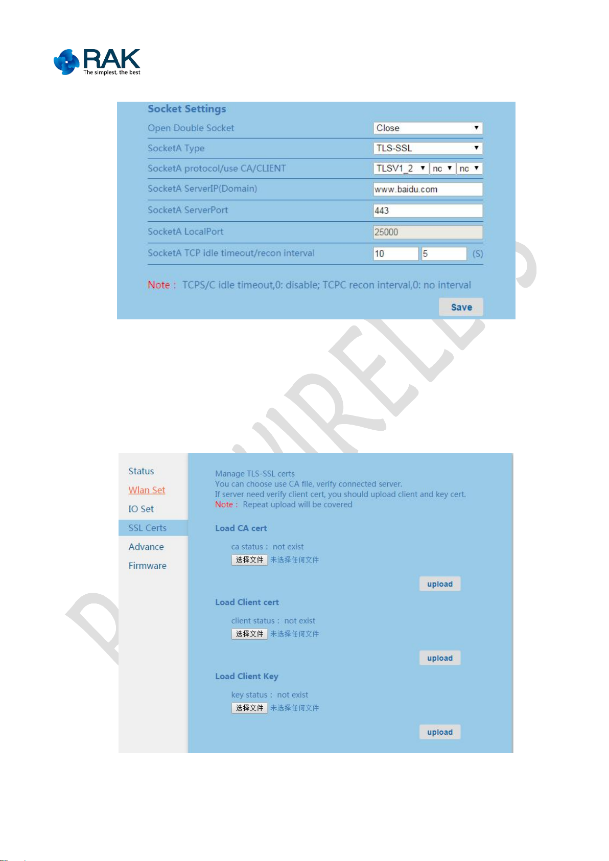
TLS/SSL secure connection, the protocol type can be optional, namely, SSLV3,
TLSV1, TLSV1_1, TLSV1_2, Auto is automatic type, namely, SSL_TLS mixture.
You can choose whether to use a CA certificate or a client certificate. Related
certificates can be set in the certificate management.
Copyright © Shenzhen Rakwireless Technology Co., Ltd
ETDX1602241830
21
RAK475 Instruction manual
Figure 3-7 TLS/SSL Set page
3.2.4 Certificate management
Certificate management interface can upload CA certificate, client certificate and
client private key file. The status of the certificate is divided into: does not exist, not
used and has been used.
Figure 3-8 IO Communication settings page of the module
Copyright © Shenzhen Rakwireless Technology Co., Ltd
ETDX1602241830
22
RAK475 Instruction manual
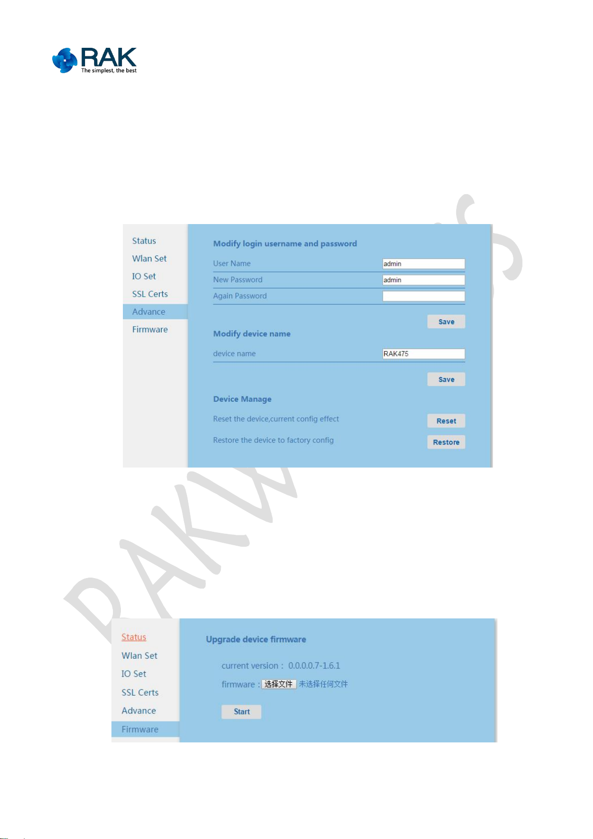
3.2.5 Equipment management
In the equipment management, the user name and password for logging on web
3.2.6 Firmware upgrading
1. WEB upgrading
page can be modified so as to improve the security of the module. Modify the
module name, as being the host name of the module can be displayed in the
connected router. In the equipment management, the restart and recovering Factory
Defaults parameters function buttons are provided.
Figure 3-9 Advanced management page of the module
The module supports the wireless upgrading function to facilitate customers to
assess. Please be careful in upgrading, contact RAK technological support if
required.
Figure 3-10 Module firm ware upgrading page
Copyright © Shenzhen Rakwireless Technology Co., Ltd
ETDX1602241830
 Loading...