

Page 1

www.raisecom.com
ISCOM2926 Hardware Installation
User Manual
Page 2

Legal Notices
Raisecom Technology Co., Ltd makes no warranty of any kind with regard to this manual,
including, but not limited to, the implied warranties of merchantability and fitness for a particular
purpose. Raisecom Technology Co., Ltd shall not be held liable for errors contained herein or direct,
indirect, special, incidental or consequential damages in connection with the furnishing, performance,
or use of this material.
Warranty.
A copy of the specific warranty terms applicable to your Raisecom product and replacement parts
can be obtained from Service Office.
Restricted Rights Legend.
All rights are reserved. No part of this document may be photocopied, reproduced, or translated to
another language without the prior written consent of Raisecom Technology Co., Ltd
. The
information contained in this document is subject to change without notice.
Copyright Notices.
Copyright ©2007 Raisecom
. All rights reserved.
No part of this publication may be excerpted, reproduced, translated or utilized in any form or by any
means, electronic or mechanical, including photocopying and microfilm, without permission in
Writing from Raisecom Technology Co., Ltd
.
Trademark Notices
is the trademark of Raisecom Technology Co., Ltd.
Java™ is a U.S. trademark of Sun Microsystems, Inc.
Microsoft® is a U.S. registered trademark of Microsoft Corporation.
Windows NT® is a U.S. registered trademark of Microsoft Corporation.
Windows® 2000 is a U.S. registered trademark of Microsoft Corporation.
Windows® XP is a U.S. registered trademark of Microsoft Corporation.
Windows® and MS Windows® are U.S. registered trademarks of
Microsoft Corporation.
Page 3

Contact Information
T echnical Assistance Center
The Raisecom TAC is available to all customers who need technical assistance with a Raisecom
product, technology, or, solution. You can communicate with us through the following methods:
Address: 2
nd
Floor, South Building of Rainbow Plaza, No.11 Shangdi Information Road,
Haidian District, Beijing 100085
Tel: +86-10-82883305
Fax: +86-10-82883056
W orld W ide Web
You can access the most current Raisecom product information on the World Wide Web at the
following URL:
http://www.raisecom.com
Feedback
Comments and questions about how the ISCOM2926 device works are welcomed. Please review the
FAQ in the related manual, and if your question is not covered, send email by using the following
web page:
http://www.raisecom.com/en/xcontactus/contactus.htm
.
If you have comments on the ISCOM2926 device specification, instead of the web page above,
please send comments to:
We hope to hear from you!
Page 4

CONTENTS
General Safety Instructions------------------------------------------------------------------------------ 1
Chapter 1 Overview ------------------------------------------------------------------------------------- 3
1.1 Overview of this manual-----------------------------------------------------------------------------------------------------3
1.2 Terms explanation-------------------------------------------------------------------------------------------------------------3
Chapter 2 Specification and Dimension---------------------------------------------------------- 4
2.1 Device hardware description -----------------------------------------------------------------------------------------------4
2.2 Device dimension -------------------------------------------------------------------------------------------------------------4
2.3 Device operating environment ---------------------------------------------------------------------------------------------4
Chapter 3 Device Appearance -----------------------------------------------------------------------5
3.1 Device front panel description----------------------------------------------------------------------------------------------5
3.2 Device rear panel description ----------------------------------------------------------------------------------------------6
Chapter 4 Installation and Application------------------------------------------------------------ 8
4.1 Device model-------------------------------------------------------------------------------------------------------------------8
4.2 Device installation-------------------------------------------------------------------------------------------------------------8
4.2.1 Environment requirement ----------------------------------------------------------------------------------------------------------------8
4.2.2 Install the device on to a rack-----------------------------------------------------------------------------------------------------------8
4.2.3 Grounding------------------------------------------------------------------------------------------------------------------------------------8
4.3 The connection of the switch-----------------------------------------------------------------------------------------------8
4.3.1 Connect to console ------------------------------------------------------------------------------------------------------------------------8
4.3.2 Connect to the Ethernet ---------------------------------------------------------------------------------------------------------------- 10
4.3.3 Connect to the power supply---------------------------------------------------------------------------------------------------------- 10
4.4 Cable making----------------------------------------------------------------------------------------------------------------- 11
4.5 Electrify the switch ----------------------------------------------------------------------------------------------------------12
Chapter 5
Notes -----------------------------------------------------------------------------------------13
Page 5
www.raisecom.com User Manual
1
General Safety Instructions
The following instructions serve as a general guide for the safe installation and operation of telecommunications
products. Additional instructions, if applicable, are included inside the manual.
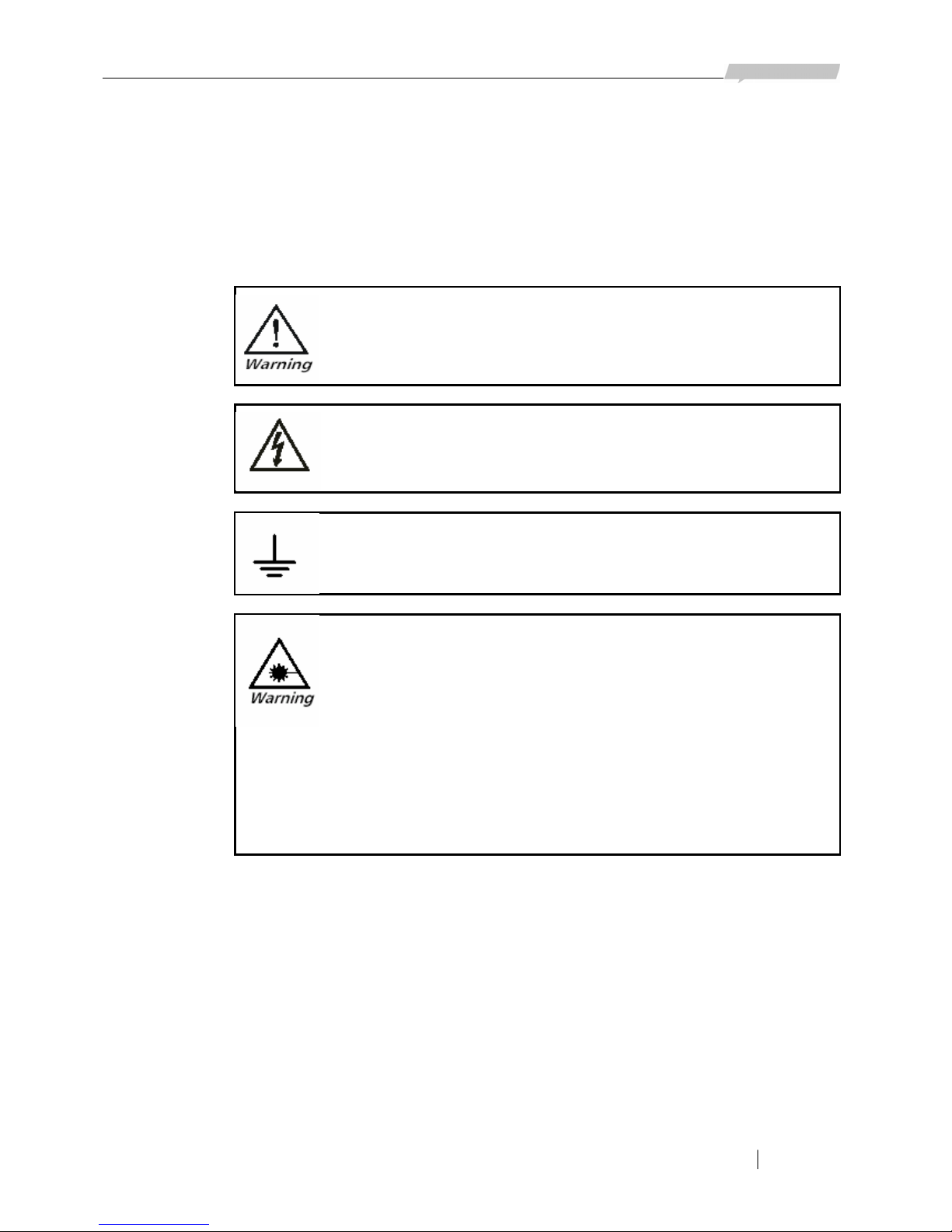
Safety Symbols
This symbol may appear on the equipment or in the text. It indicates potential
safety hazards regarding product operation or maintenance to operator or service
personnel.
Danger of electric shock! Avoid any contact with the marked surface while the
product is energized or connected to outdoor telecommunication lines.
Protective earth: the marked lug or terminal should be connected to the building
protective earth bus.
Some products may be equipped with a laser diode. In such cases, a label with
the laser class and other warnings as applicable will be attached near the optical
transmitter. The laser warning symbol may be also attached.
Please observe the following precautions:
• Before turning on the chassis with optic module, make sure that the fiber optic
cable is intact and is connected to the transmitter.
• Do not attempt to adjust the laser drive current.
• Do not use broken or unterminated fiber-optic cables/connectors or look straight at the
laser beam.
• The use of optical devices with the equipment will increase eye hazard.
• Use of controls, adjustments or performing procedures other than those specified herein, may
result in hazardous radiation exposure.
ATTENTION: The laser beam may be invisible!
Always observe standard safety precautions during installation, operation and maintenance of this
product. Only qualified and authorized service personnel should carry out adjustment, maintenance
or repairs to this product. No installation, adjustment, maintenance or repairs should be performed by
either the operator or the user.
All extension slots are not hot-swappable
Before operating modules in the electricity conditions, please be noticed that optical modules shall
be connected with optical fiber wires or shield with optical module cover for fear that laser light
harms to operator’s eyes.
Handling Energized Products
General Safety Practices
Do not touch or tamper with the power supply when the power cord is connected. Line voltages may
Page 6

www.raisecom.com User Manual
2
be present inside certain products even when the power switch (if installed) is in the OFF position or
a fuse is blown. For DC-powered products, although the voltages levels are usually not hazardous,
energy hazards may still exist.
Before working on equipment connected to power lines or telecommunication lines, remove jewelry
or any other metallic object that may come into contact with energized parts.
Unless otherwise specified, all products are intended to be grounded during normal use. Grounding
is provided by connecting the mains plug to a wall socket with a protective earth terminal. If an earth
lug is provided on the product, it should be connected to the protective earth at all times, by a wire
with a diameter of 18 AWG or wider. Rack-mounted equipment should be mounted only in earthed
racks and cabinets.
Always make the ground connection first and disconnect it last. Do not connect telecommunication
cables to ungrounded equipment. Make sure that all other cables are disconnected before
disconnecting the ground.
Connection of AC Mains
Make sure that the electrical installation complies with local codes.
Always connect the AC plug to a wall socket with a protective ground.
Always connect the power cord first to t he equipment and then to the wall socket. If a power switch
is provided in the equipment, set it to the OFF position. If the power cord cannot be readily
disconnected in case of emergency, make sure that a readily accessible circuit breaker or emergency
switch is installed in the building installation.
Connection of DC Mains
Unless otherwise specified in the manual, the DC input to the equipment is floating in reference to
the ground. Any single pole can be externally grounded.
Due to the high current capability of DC mains systems, care should be taken when connecting the
DC supply to avoid short-circuits and fire hazards.
DC units should be installed in a restricted access area, i.e. an area where access is authorized only to
qualified service and maintenance personnel.
Make sure that the DC supply is electrically isolated from any AC source and that the installation
complies with the local codes.
Before connecting the DC supply wires, ensure that power is removed from the DC circuit. Locate
the circuit breaker of the panel board that services the equipment and switch it to the OFF position.
When connecting the DC supply wi res, first connect the ground wire to the corresponding te rminal,
then the positive pole and last the negative pole. Switch the circuit breaker back to the ON position.
A readily accessible disconnect device that is suitably rated and approved should be incorporated in
the building installation.
Preventing Electrostatic Discharge Damage
Modules which can be plugged into chassis are sensitive to damage from static electricity.
Conversely, static voltages as high as 35,000V can be generated just by handling plastic or foam
packing material, or by sliding assemblies across plastic and carpets. Not exercising the proper
electrostatic discharge (ESD) precautions can result in intermittent or complete component failures.
To minimize the potential for ESD damage, observe the following guidelines:
• Always use an ESD-preventive antistatic wrist strap or ankle strap and ensure that it makes good
skin contact.
• When removing or installing a component, make sure the equipment end of your antistatic strap
leash is connected to the ESD connection sockets on the front of the chassis or to a bare metal
surface on the chassis. Avoid contact between the component and your clothing. The wrist strap only
protects the component from ESD voltages on the body; ESD voltages on your clothing can still
cause component damage.
• Always place a card component-side-up on an antistatic surface, in an antistatic card rack, or in a
static shielding bag. If you are returning the item to the factory, immediately place it in a static
shielding bag.
• Handle Modules by the metal card carrier edges only; Avoid touching the board or any connector
pins.
Page 7

www.raisecom.com User Manual
3
Chapter 1 Overview
1.1 Overview of this manual
This manual mainly discusses the installation of ISCOM2926 switch. It describes the features of the
switch, introduces its components and the functions these components accomplish. The manual
brings forth a normative installation procedure for users and explains the types and specifications of
all cables applied during the installation.
This manual focuses on the hardware installation and employment of ISCOM2926 switch. For the
configuration and operations of the switch based on software, please refer to the corresponding
software configuration guide.
1.2 Terms explanation
10BASE-T A term in IEEE 802.3 for Ethernet over CAT-3 or better twisted pair,
based on Manchester coding and running at 10Mbps.
100BASE-TX A term in IEEE 802.3 for Fast Ethernet over CAT-5 twisted pair, based on
4B/5B coding and running at 100Mbps.
1000BASE-X A term in IEEE 802.3 for Gigabit Ethernet over fiber, based on 8B/10B
coding and running at 1000Mbps.
Auto
Negotiation
The auto negotiation procedure is: the port at one site adapts its bit rate
and duplex mode to the highest level it and the opposite site device both
support according to the bit rate and duplex mode adopted by the remote
site device, that is, the connected devices on both site adopt the fastest
transmission mode they both support after the auto negotiation process.
Full Duplex A communication pattern that allows communication in both directions
simultaneously.
Half Duplex A communication pattern that allows communication in both directions,
but only one direction at one time.
RJ-45 The 8 position modular connector applied in twisted pair cable link
MDI Medium Dependent Interface, the name for the connector physically and
electrically connects the media converter and the media segment.
MDIX Medium Dependent Interface Crossover, it sends the transmitting signal
of a device to the receiving port of the opposite device and vice versa.
Page 8

www.raisecom.com User Manual
4
Chapter 2 Specification and Dimension
2.1 Device hardware description
ISCOM2926 Ethernet Switch is a layer-2 Ethernet switch designed for network users’ access to the
carriers’ network. ISCOM2926 provides 24 10/100BASE-TX Ethernet electrical interfaces and 2
1000BASE-X interfaces in the form of SFP. The power consumption of the system is less than 40W.
2.2 Device dimension
The dimension of ISCOM2926 switch’s main structure is: 1U (Height) x 442mm (Width) x 266mm
(Depth). The device weighs 3.5kg and can be either fixed in a 19-inch cabinet or placed on a table.
2.3 Device operating environment
Environment temperature: 0°C ~ 55°C
Storage temperature: - 40°C ~ 70°C
Environment humidity: 10% ~ 90%
Page 9
www.raisecom.com User Manual
5
Chapter 3 Device Appearance
3.1 Device front panel description
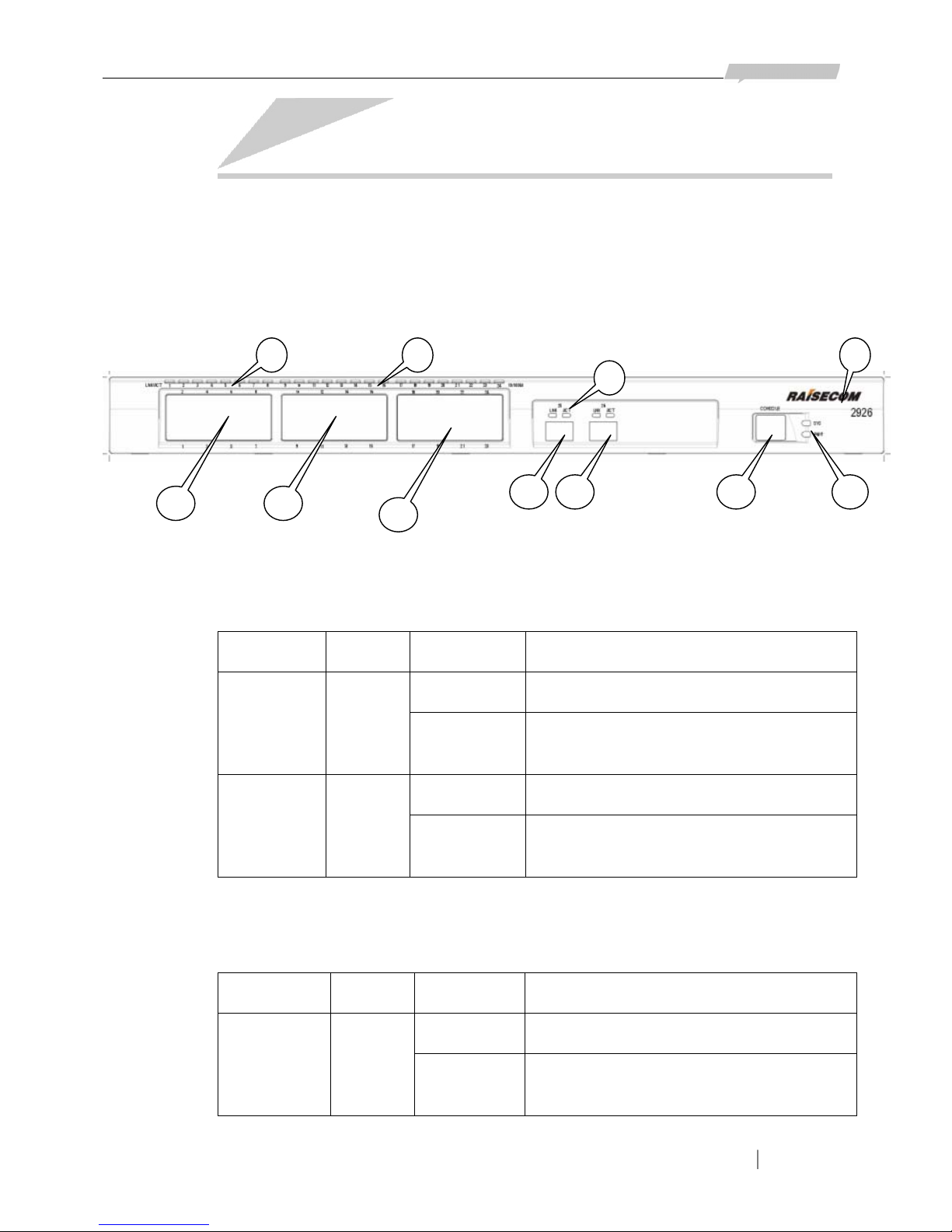
24 10/100M Ethernet interfaces in the form of RJ-45, 1 CONSOLE interface, 2 SFP interfaces and
dozens of status indicators are placed on the front panel of ISCOM2926 switch (see the figure
below).
In the figure shown above:
① The logo and model of the switch are RAISECOM and 2926 respectively.
② 2 device status indicators: SYS and PWR.
Indicator Color Status Description
Flickering The system is operating in order. SYS Green
Other
Status
The system is initializing or software fault
occurs.
ON The power supply module is electrified. PWR Green
OFF The power supply module is not electrified or
fault occurs at the power supply.
③ 24 10/100Mbps Ethernet interfaces
④ The status indicators for the 24 10/100Mbps Ethernet interfaces. There are 2 indicators for each
interface: LNK/ACT and 100M.
Indicator Color Status Definition
ON The corresponding port is in Link Up status. LNK/ACT Green
Flickering The corresponding port is transmitting or
receiving data.
1
2
3 3
3
4
5 5
4
6
7
Page 10
www.raisecom.com User Manual
6
OFF The corresponding port is in Link Down
status.
ON In Link Up status, the electrical interface is
working at the rate of 100Mbps.
100M Green
OFF In Link Up status, the electrical interface is
working at the rate of 10Mbps.
⑤ 2 1000Base-X Ethernet interfaces in the form of SFP
⑥ The status indicators for the 2 1000Base-X Ethernet interfaces in the form of SFP. There are 2
indicators for each port, and they are titled LNK and ACT.
Indicator Color Status Description
ON The corresponding port is in Link Up status. LNK Green
OFF The corresponding port is in Link Down status.
Flickering There is data being transmitted or received at
the corresponding port.
ACT Green
OFF No data is being transmitted or received at the
corresponding port.
⑦ The CONSOLE interface
3.2 Device rear panel description
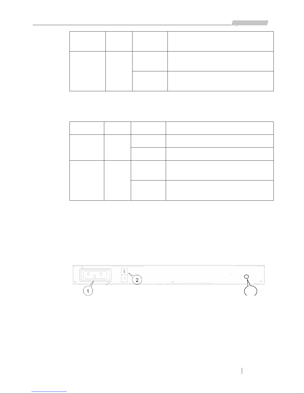
ISCOM2926 provides a socket for 100~220V AC power supply or a socket for -48V DC power
supply on its rear panel (see the figure below). Users can choose either of them according to need.
1) The socket for 100~220V AC power supply
3
In the figure shown above:
① The place where the socket for 100~220V AC power supply locates.
② The place where the switch for 100~220V AC power supply locates.
③ The place where the grounding terminal locates.
2) The socket for -48V DC power supply
Page 11

www.raisecom.com User Manual
7
3
In the figure shown above:
① The place where the socket for -48V DC power supply locates. PGND is the chassis ground. The
-48 and BGND are the -48V DC power supply.
② The place where the switch for -48V DC power supply locates.
③ The place where the grounding terminal locates.
Page 12

www.raisecom.com User Manual
8
Chapter 4 Installation and Application
4.1 Device model
The device models currently provided are:
Product Model Description
ISCOM2926-AC Layer-2 switch; 24 10/100BASE-TX Ethernet interfaces in the form of
RJ-45 and 2 1000M Ethernet interfaces in the form of SFP; 100~220V
AC power supply; Single power supply
ISCOM2926-DC Layer-2 switch; 24 10/100BASE-TX Ethernet interfaces in the form of
RJ-45 and 2 1000M Ethernet interfaces in the form of SFP; -48V DC
power supply; Single power supply
4.2 Device installation
4.2.1 Environment requirement
There are heat exhaust outlets on both sides of ISCOM2926 switch. Please leave space on both sides
of the switch to keep air flow unblocked. Please make sure the outlets are not blocked.
4.2.2 Install the device on to a rack
To set the switch firmly into a rack, please fix the installation tray to the switch using the four screws
come with the device and fasten the installation handle on to the rack.
4.2.3 Grounding
To ensure the safety of the device and the operator, please make sure that the grounding terminal is
well connected to the earth.
4.3 The connection of the switch
4.3.1 Connect to console
ISCOM2926 switch provides a RS-232C interface in the form of RJ-45 as the CONSOLE interface.
After connecting the CONSOLE interface of ISCOM2926 switch to the serial port on the PC using
the provided cable, users can configure and manage the switch through PC.
1) CONSOLE interface signal definitions of the switch
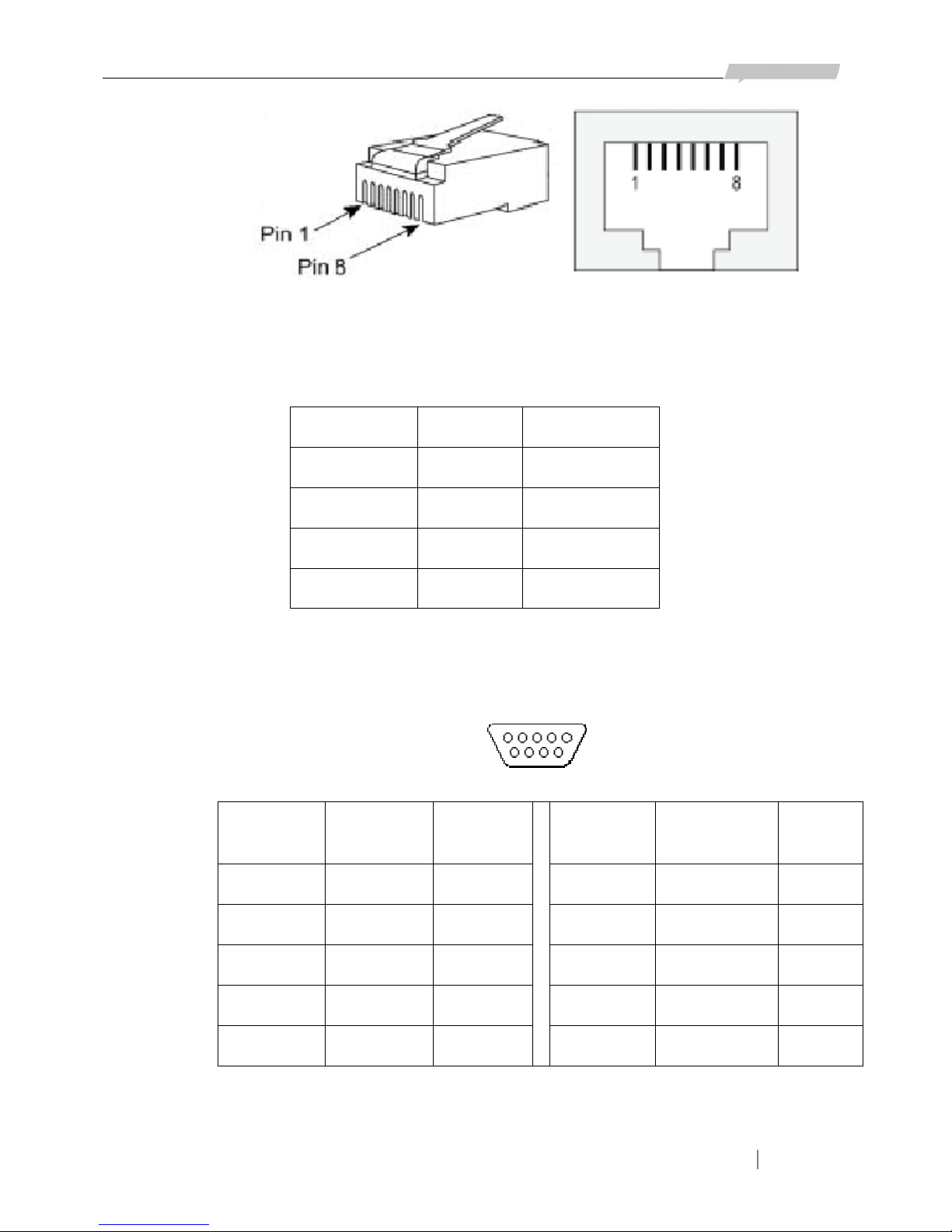
The CONSOLE interface of ISCOM2926 is in the form of RJ-45. The RJ-45 connector and jack and
the corresponding pin number is shown in the figure below.
Page 13
www.raisecom.com User Manual
9
RJ-45 Connector RJ-45 Jack
The corresponding pin function definition of ISCOM2926 CONSOLE interface is shown in the table
below:
Pin Number Function Type
3 RxD IN
6 TxD OUT
4, 5 GND Ground
1, 2, 7, 8 N.C. No connection
2) PC serial port signal definition
The pin number and pin function definition of 9-pin serial port connector is shown in the figure and
table below.
Pin
Number
Function Type Pin
Number
Function Type
1 CD 6 DSR
2 RxD IN 7 RTS
3 TxD OUT 8 CTS
4 DTR 9 RI
5 GND Ground
3) CONSOLE interface connecting pattern and parameter setup
The connecting of ISCOM2926 CONSOLE interface and PC serial port is shown in the figure below.
Page 14

www.raisecom.com User Manual
10
RxD
TxD
GND
RxD
TxD
GND
PC Serial Pot
ISCOM2926 CONSOLE
3
2
5
6
3
4、5
The values of the connecting parameters of the terminal simulation program on the PC are as
follows:
9 Baud Rate: 9600
9 Data Bit: 8
9 Stop Bit: 1
9 Parity Bit: None
9 Flow Control: None
4.3.2 Connect to the Ethernet
ISCOM2926 switch provides 24 10/100M self-adaptive Ethernet interfaces in the form of RJ-45 and
2 1000Base-X Ethernet interfaces in the form of SFP. By default, the 10/100M Ethernet interfaces
are set to be working at the rate of 100Mbps and in full-duplex mode.
The 24 10/100M Ethernet interfaces of ISCOM2926 switch has Auto MDI/MDIX function when the
auto negotiation function is enabled, that is, the device can switch between MDI and MDIX
automatically. The connection can be established successfully regardless of the type of interface
(MDI or MDIX) the opposite site of the connection adopts or the type of cable (straight through or
crossover) applied.
For RJ-45, the definition of MDI and MDIX signal is shown in the table below. For the pin
numbering of RJ-45 connector and jack, please refer to the “CONSOLE interface signal definitions
of the switch” in section 4.3.1.
Pin Number MDIX Signal MDI Signal
1 RD+ TD+
2 RD- TD-
3 TD+ RD+
6 TD- RD-
4, 5, 7, 8 N.C. N.C.
The Ethernet electrical interfaces of ISCOM2926 switch works at MDIX mode when the auto
negotiation function is disabled. In this circumstance, the interface can be connected to an opposite
PC with MDI interface by straight through cable.
4.3.3 Connect to the power supply
1) ISCOM2926-AC adopts 100~220V AC power supply. Please connect the socket on the rear panel
of the switch with 100~220V AC power supply using the provided power supply cable.
Page 15

www.raisecom.com User Manual
11
Note that there is a switch for the 100~220V AC power supply on ISCOM2926. After connecting
ISCOM2926 to 100~220V AC power supply, please turn on the switch to begin the electrifying of
the device.
2) ISCOM2926-DC adopts -48V DC power supply. Please connect the socket on the rear panel of the
switch with -48V DC power supply using the provided power supply cable.
Note that there is a switch for the -48V DC power supply on ISCOM2926. After connecting
ISCOM2926 to the power supply, please turn on the switch to begin the electrifying of the device.
4.4 Cable making
For the pin numbering of RJ-45 connector and jack, please refer to the “CONSOLE interface signal
definitions of the switch” in section 4.3.1.
1) Straight through cable (The straight through cable for 100M or 1000M are ident ica l.)
Side 1
1
1
Side 2
Side 1 Side 2
3
5 74 62 8
3574628
1 = White/Orange
7 = White/Brown
1 = White/Orange
2 = Orange
3 = White/Green
4 = Blue
5 = White/Blue
6 = Green
7 = White/Brown
8 = Brown
2 = Orange
3 = White/Green
4 = Blue
5 = White/Blue
6 = Green
8 = Brown
2) 100M Crossover cable
1
1
7 = White/Brown
Side 2
Side 1 Side 1 Side 2
1 = White/Gre en
3 = White/Orange
3 5 74 62 8
3574628
1 = White/Orange
2 = Orange
3 = White/Green
4 = Blue
5 = White/Blue
6 = Green
7 = White/Brown
8 = Brown
2 = Green
4 = Blue
5 = White/Blue
6 = Orange
8 = Brown
2) 1000M Crossover cable
Page 16

www.raisecom.com User Manual
12
1
1
Side 1
3
5 74 62 8
3574628
Side 2
Side 1 Side 2
1 = White/Orange
2 = Orange
3 = White/Green
4 = Blue
5 = White/Blue
6 = Green
7 = White/Brown
8 = Brown
1 = White/Green
2 = Green
3 = White/Orange
4 = White/Brown
5 = Brown
6 = Orange
7 = Blue
8 = White/Blue
4.5 Electrify the switch
¾ After installing the switch following the steps above, connect the switch to 100~220V AC
power supply (or -48V DC power supply) using the provided power supply cable, and then
the switch is electrified.
¾ After the electrifying, the indicator PWR will turn ON to indicate that the power supply of
the system is working.
¾ The switch will begin its self-check and initialization in succession. All the indicators on the
front panel of the switch will turn ON during this procedure.
¾ The switch will be in operating status after the self-check and initialization. The indicator
SYS will begin to flicker to indicate that the system in operating normally. The indicators for
Ethernet ports will show the status of their corresponding ports (ON or OFF according to the
settings and connection of the port).
¾ Here, if the switch is connected to PC via CONSOLE interface before electrifying and the
terminal software is correctly configured, the user management interface on which users can
operate over the switch will appear on the PC (For details, please refer to the corresponding
software configuration manual.).
Page 17

www.raisecom.com User Manual
13
Chapter 5 Notes
The installation, maintenance, plugging in and pulling out of components of ISCOM2926 switch can
only be conducted by qualified technical support staff. Please place the device in a
temperature-controllable and humidity-controllable room and please be cautious of the conductivity
of the materials around the device. Please note that a room with high humidity exposes the device to
short circuit; while low humidify may lead to fire alarm. In a word, the switch must be placed in
proper surroundings.
¾ The power supply of the device should be well earthed to let out the static electricity.
¾ Please keep some space from other powered devices when installing the switch.
¾ The cable arrangement of the switch should have all cables be placed across the live wire.
Long-distance close parallel of the cables and the live wire must be avoided.
¾ Please operate following the instructions in this manual strictly.
¾ Please avoid operating the switch with wet hands or hands with too much sweat.
¾ Any mechanical and electrical modifications to the switch are strictly forbidden.
Page 18

Address: 2
nd
Floor, South Building of Rainbow Plaza, No.11 Shangdi Information Road,
Haidian District, Beijing Postcode: 100085 Tel: +86-10-82883305 Fax: +86-10-82883056
Email: [email protected] http://www.raisecom.com
 Loading...