

Page 1

ISCOM 1005M(A)
User Manual
Raisecom Technology Co., Ltd .
Dec, 2005
Page 2

User manual
Content
1. Cautions.........................................................................................................................3
2. ISCOM 1005M(A) Overview .......................................................................................4
2.1Package ................................................................................................................4
3. Parameters.....................................................................................................................4
3.1 Features:..............................................................................................................4
3.2 Specifications:.....................................................................................................5
3.3 Environment and power:.....................................................................................5
4. Mechanical structure and indicators..............................................................................5
5. How to manage ISCOM 1005M(A)..............................................................................6
5.1 Manual overview.................................................................................................6
5.2 Configure ISCOM 1005M(A).............................................................................7
5.2.1 Log on ......................................................................................................7
5.2.2 PORT SETUP...........................................................................................7
5.2.3Port VLAN Setting....................................................................................8
5.2.4 T AG VLAN setting..................................................................................9
5.2.5Modify password.....................................................................................11
5.2.6Advanced setting.....................................................................................11
5.2.7Restore default setting.............................................................................12
5.2.9 Exit.........................................................................................................12
6. Troubleshooting...........................................................................................................13
6.1 How to resolve the link LED off.......................................................................13
6.2 Q&A..................................................................................................................13
Appendix A .....................................................................................................................13
A. Sketch map for cables.................................................................................13
B. Cable types and function ............................................................................14
C. CBL-RS232-DB9F/RJ45-A-2m.........................................................................14
Page 3
User manual
1. Cautions
Please read the following notice carefully before
installing and using the device, Raisecom shall not be
responsible for any loss that caused by violating
safety notice.
ISCOM1005M(A) is integrated device that has precise
elements, please avoid violent shakes and impacts,
and do not disassemble or maintain the device
yourself. If it is required, please do it under the guide
of our technical staff following in the steps of anti
static. Please contact us if there is any need.
There must be grounding protection for the sake of
safety; do not disassemble the device yourself, we
regard it as you waiver your rights of repair
guarantee.
Page 4

User manual
4
2. ISCOM 1005M(A) Overview
ISCOM 1005M(A) is 5-port Ethernet switch complied with 802.1Q VLAN and
supports Console local management and traffic, bandwidth management.
2.1Package
z 1 unit ISCOM 1005M(A)
z 1 piece DC 5V power cord
z 1 piece CBL-RS232-DB9F/RJ45-A-2m connection cable
3. Parameters
3.1 Features:
z 5x10/100Mbps RJ45 interface
z It supports MDI or MDI-X
z It supports CONSOLE local management
z Bi-directional Nx32Kbps bandwidth management
z It supports flow control
z It supports PORT VLAN and TAG VLAN
z It supports broadcast filtering
Page 5
User manual
5
3.2 Specifications:
Protocols : IEEE802.3 10Base-T,IEEE 802.3u 100Base-TX IEEE802.3x
Cables: 10Mbps:3,4,5 CAT twisted pairs. 100Mbps:CAT5 Twisted pair;
Number: 5xRJ45
VLAN: supports port-VLAN and TAG VLAN
Panel: PWR,SYS,LNK/ACT,100M,FDX
Dimension: 139.5Wmm x 77Dmm x 28Hmm
Store and forward: full wire speed
MAC table:1K
Buffer:64K
Certification: CE MARK
3.3 Environment and power:
Environment Temp:0~50 centigrade
Humidity: 5% ~ 95%
Power consumption: く 5W
Power: 100-240VAC,50-60Hz
4. Mechanical structure and indicators
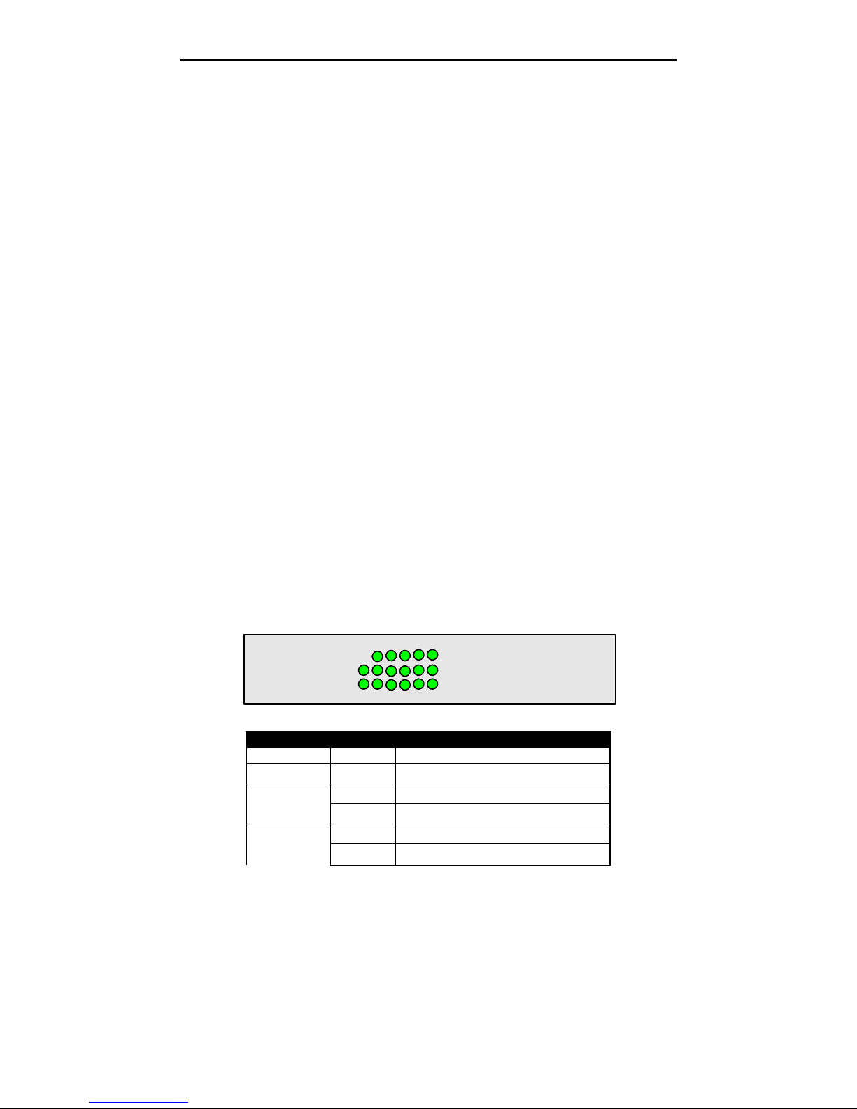
LEDs provide all of information and status of interface of Ethernet switch.
123 45
LNK/ACT
100M
FDXPWR
SYS
ISCOM 1005M
LED
状态 条件
PWR Fixed on Power is on
SYS Flashing The system is active
Fixed on Link is ok LNK / ACT
Flashing Data traffic is working
Fixed on 100Mbps 100M
Off 10Mbps
Page 6

User manual
6
Fixed on Full duplex
Off Half duplex
FDX
Flashing The data traffic is conflicting when half
duplex
5. How to manage ISCOM 1005M(A)
5.1 Manual overview
[1] Overview
z Configure the mode of system and interface
z Configure bi-directional bandwidth
z Configure PORT VLAN or TAG VLAN
z Filter broadcast packets
[2]management
z ISCOM 1005M(A) supports console management. If configuration is finished,
CONSLE interface also works as 5
th
service interface.
Local craft terminal
Ethernet switch can be managed via VT100 terminal or computer workstation
through CONSLE cable.
ISCOM 1005M(A)’s default setting as [bits per second: 9600, data bits: 8, Parity: 0,
stop bits: 1, flow control: None], VT100 type terminal.
Log on ISCOM 1005M(A)
Default password is 1234.
Page 7
User manual
7
5.2 Configure ISCOM 1005M(A)
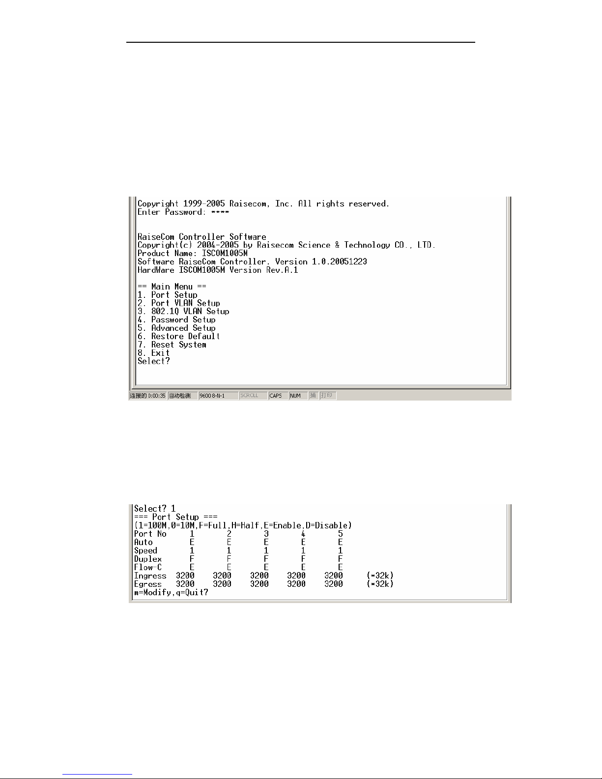
5.2.1 Log on
Input “1234” at first time. Then management screen will available.
P.S: the command is only available for lowercase. Press ”ESC” to return main manual
Choose the item through numeric key on this interface.
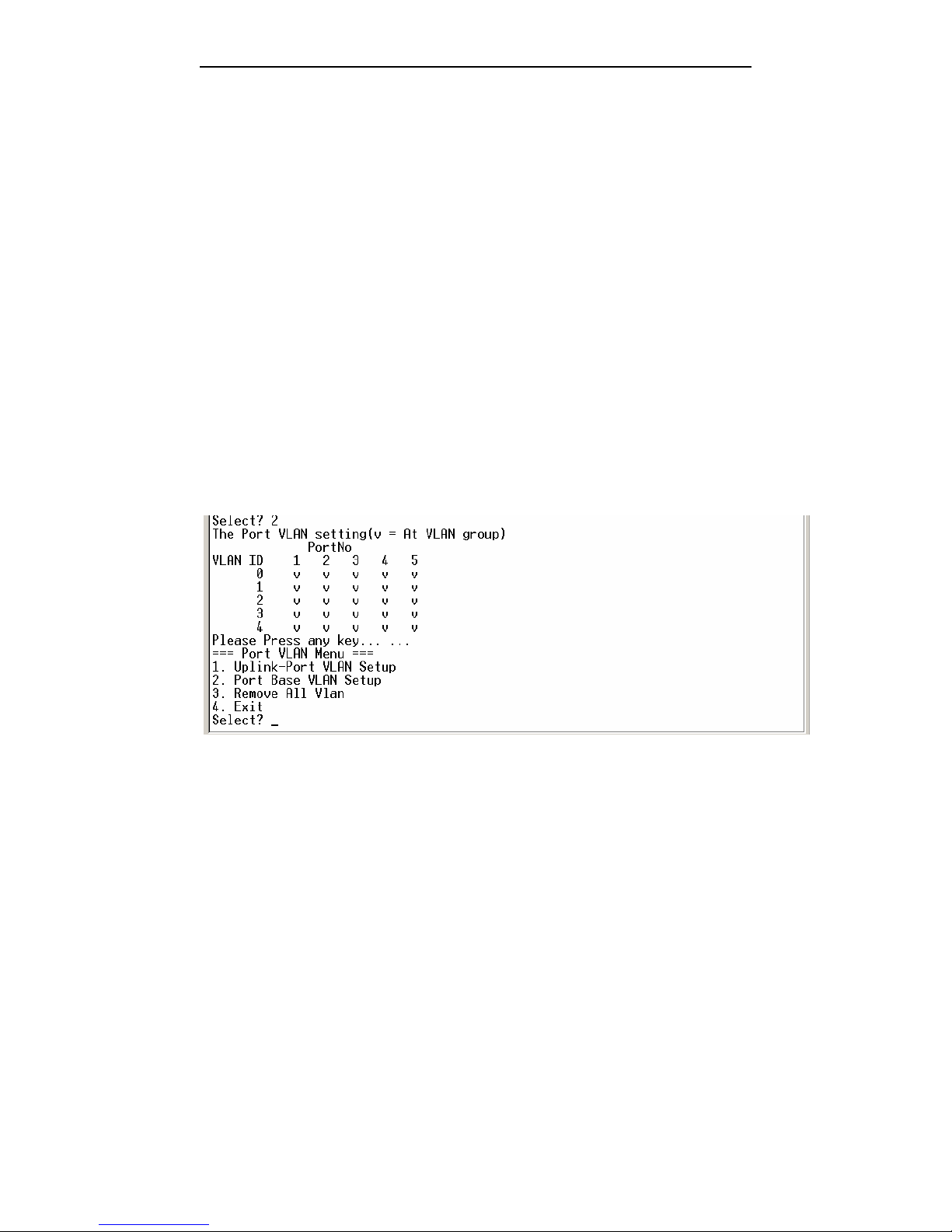
5.2.2 PORT SETUP
Choose “1” to enter the screen a s following in the main manual.
Page 8
User manual
8
1. Modify setting
Press “m” to modify the setting including:Admin(e:open,d:close)、Auto(e:
auto negotiation,d:non auto negotiation)、speed (1:100M,0:10M)、Duplex(f:
full,h:half)、flow-C(e:enable flow control,d:disable flow control). After
modification, press “y” to save, press “n” not to save.
2. Download Ingress、upload Egress bandwidth management N x 32Kbps,N is
configurable. Select “y” to save; “n” not to save.
3. Press “q” to quit and return main manual
P.S: when auto negotiation is enabled, the status and working mode on ly depend on the
device located on the other end. Manually configuration is disabled.
5.2.3Port VLAN Setting
P.S: when Port VLAN group is created, 802.1Q VLAN group must be removed
firstly.
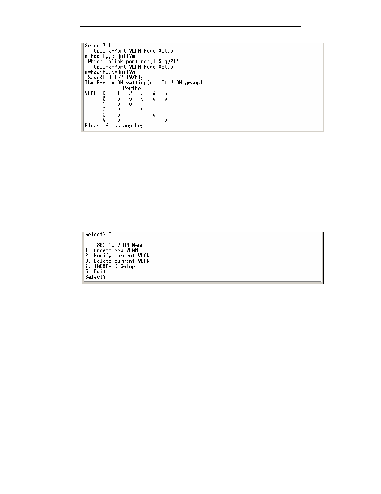
Select “2” to access Port VLAN setting interface.
Select “1”: system will ask user to assign uplink port and other ports will be
isolated each other automatically. And each port VLAN includes uplink port.
Page 9
User manual
9
Select “2”: the system will ask user to manually configure each VLAN according
the specific requirement.
Select “3”: remove all of the VLAN
5.2.4 TAG VLAN setting
P.S: before creating 802.1Q VLAN group, Port VLAN must be removed firstly.
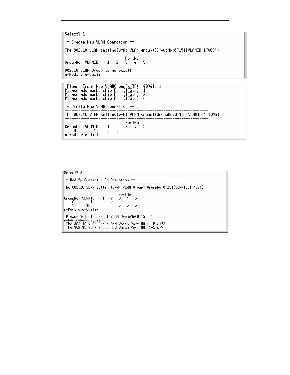
Select “3” to access TAG VLAN interface
select “1” to create VLAN domain. This device only supports 0~15 VLAN domain.
VLAN ID 1~4094
P.S: Can not configure same ID VLAN domain.
Page 10
User manual
10
select “2” to modify VLAN domain. Input “m” to access the dialog interface to
modify VLAN domain and select GroupNo: “1” (only 0~15 VLAN Group. Select the
GroupNo, not VLANID. Now try to select GroupNo.1) and select Add or Remove Port
and select Port No. Input “q” to save configuration
Select “3” to delete the created VLAN domain and input “m” to access the dialog
for deleting VLAN. Select GroupNo. Select “q” to save configuration and exit.
Page 11
User manual
11
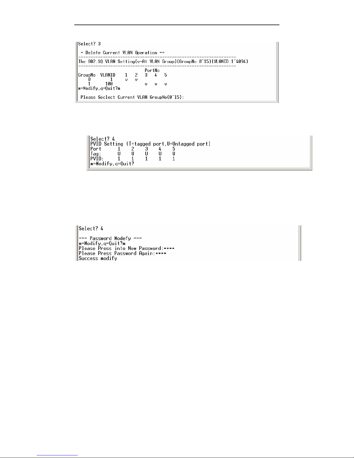
Select “4” to configure the tag of port. “TAGGED PORT” can not be connected to
“UNTAGGED PORT” of the subscriber.
5.2.5Modify password
Choose “4-Password Setup” to modify the password.
5.2.6Advanced setting
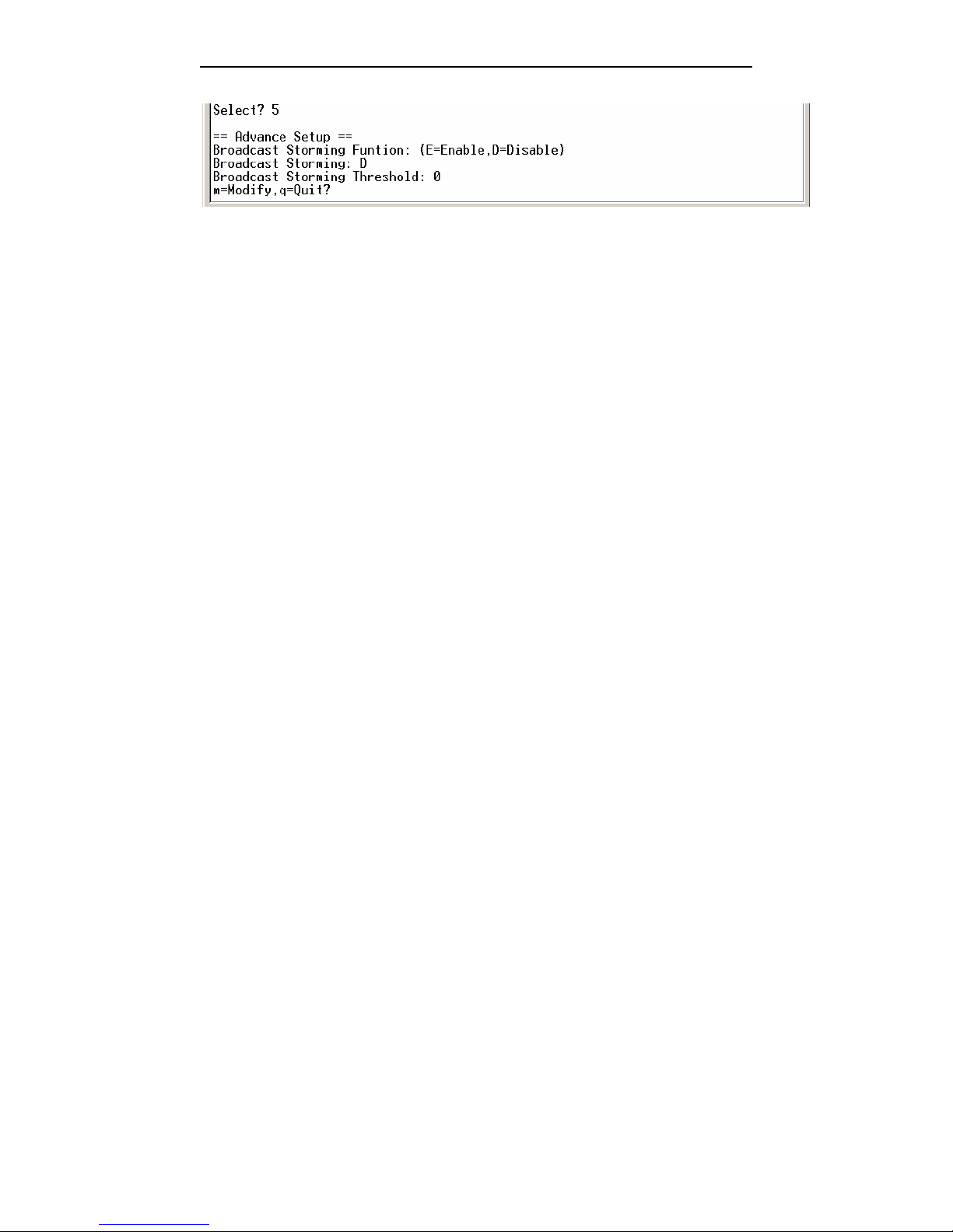
Choose “5” to access “Advanced Setup”.
Page 12
User manual
12
If the function of filtering broadcast storm is available, these broadcast packets will
be disregarded with 50ms when broadcast packets is over threshold. The customer can
configure 3 types for threshold (based on port)
1: 10% for all of interfaces;
2: 20% for all of interfaces;
3: 30% for all of interfaces.
5.2.7Restore default setting
Select “6. Restore Default” in main manual to restore default setting.
5.2.8 Reset system
Select “7. Reset System” in main manual to reset Ethernet switch
5.2.9 Exit
Select “8. Exit” to return log in interface.
Page 13

User manual
13
6. Troubleshooting
6.1 How to resolve the link LED off
The possible reasons as followings:
1.the power supply is off
2.the type of the cable is not right
3.the interface of Ethernet switch is trouble
6.2 Q&A
1. Computer A can access computer B through Ethernet switch. However, computer A
can not access computer C.
9 Computer A and computer C are maybe not in the same VLAN. Please check the
VLAN configuration through console port.
9 The network has some problem including Computer C. please check LED
LNK/ACT of computer C and try to connect other device using this interface.
9 Please check the NIC configuration of computer C.
Appendix A
z Standard straight line
z Cross over line
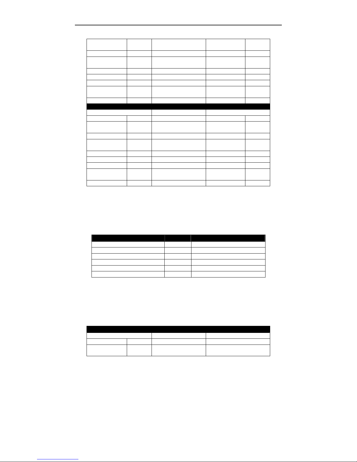
A. Sketch map for cables
Standard straight line
HUB / Switch NIC
Pin# # Pin # #
Page 14
User manual
14
1 RX+ white-green ----------------- 1 RX+ white-gree
n
2 RX- green ----------------- 2 RX- green
3 TX+ white-oran
ge
----------------- 3 TX+ white-oran
ge
4 N/A blue ----------------- 4 N/A blue
5 N/A white-blue ----------------- 5 N/A white-blue
6 TX- orange ----------------- 6 TX- orange
7 N/A white-brown ----------------- 7 N/A white-brow
n
8 N/A brown ----------------- 8 N/A brown
Standard cross over line
Hub /switch NIC
Pin # # Pin# #
1 RX+ white-green ---- ---- 1 RX+ white-oran
ge
2 RX- Green ---- ---- 2 RX- orange
3 TX+ white-oran
ge
---- ---- 3 TX+ white-gree
n
4 N/A blue 4 N/A blue
5 N/A white-blue 5 N/A white-blue
6 TX- orange ---- ---- 6 TX- Green
7 N/A white-brown 7 N/A white-brow
n
8 N/A brow 8 N/A brown
B. Cable types and function
连接关系 速率 电缆类型
HUB to HUB(or SWITCH) 10Mbps Cross over, CAT3,4,5
HUB to HUB(or SWITCH) 100Mbps Cross over, CAT5
HUB to Server or workstation 10Mbps Straight line, CAT3,4,5
HUB to Server or workstation 100Mbps Straight line, CAT5
HUB to print server 10Mbps Straight line, CAT3,4,5
HUB to print server 100Mbps Straight line, CAT5
C. CBL-RS232-DB9F/RJ45-A-2m
标准直连线
CONSOLE DB9
Pin # Pairs # Pin #
1 RX+ White
–green
----------------- 1 unavailable
Page 15

User manual
15
2 RX- Green ----------------- 2 RXD
3 TX+ White-
orange
----------------- 3 TXD
4 RXD Blue ----------------- 4 unavailable
5 GND White –
blue
----------------- 5 GND
6 TX- Orange ----------------- 6 unavailable
7 GND White-bro
wn
----------------- 7 unavailable
8 TXD Brown ----------------- 8 unavailable
----------------- 9 unavailable
 Loading...