

Page 1
Rev: V1.0
3D Printer Manual
RAISE3D PRO2 SERIES
www.raise3d.com
Shanghai Fusion Tech Co., Ltd.
4th Floor, B5 Building, No.1600 Guoquan N Rd, Shanghai, China 200438
Page 2

CONTENTS
WWW.RAISE3D.COM
AMERICA · ASIA · EUROPE
1
CONTENTS
Safty ............................................................................................................ 1
Electromagnetic Compatibility-EMC ............................................................ 5
Technical Specifications – Pro2 / Pro2 Plus ................................................. 7
Printer Components .................................................................................... 8
Spare Parts ................................................................................................ 10
Hardware Installation ................................................................................ 10
Operation .................................................................................................. 15
Wire Diagram ............................................................................................ 16
Page 3
SAFTY
Warning: Indicates a potentially hazardous situation which, if not avoided, may result in injury or
damage.
Hot Nozzle: The hot nozzle sign indicates the presence of devices with high temperatures. Always
use extra care when working around heated components. Always wear the heat resistant gloves provided in the
Starter Box.
Nozzle temperatures in the printer can exceed 300℃(572℉).
Hot Surface: The hot surface sign indicates the presence of devices with high temperatures. Always
use extra care when working around heated components. Always wear the heat resistant gloves provided in the
Starter Box.
Moving Parts: The moving parts sign indicates that a hazard exists where you touched, it can cause
serious bodily injury. Always keeps hands clear of Moving Parts.
High Voltage: The high voltage sign indicates the presence of high voltages. Always stay away from
any exposed electrical circuitry. It is recommended that all jewelry be removed.
Page 4

ELECTROMAGNETIC COMPATIBILITY
WWW.RAISE3D.COM
AMERICA · ASIA · EUROPE
3
Electromagnetic Compatibility-EMC
Simplified EU Declaration of Conformity
Pro2/Pro2 Plus declares that this device is in compliance with the essential requirements and other relevant
provision of Directive 2014/53/EU.Full tex of EU declaration of conformity is available at
https://www.raise3d.com
The WIFI operation in the band 5150-5250MHz shall be restricted to indoor use for countries listed in the table
below:
AT
BE
BG
CZ
DK
EE
FR
DE
IS
IE
IT
EL
ES
CY
LV
LI
LT
LU
HU
MT
NL
NO
PL
PT
RO
SI
SK
TR
FI
SE
CH
UK
HR
Pro2/Pro2 Plus CE Output power table:
Function
Frequency
Maximum Output Power
(EIRP)
WiFi
2412-2472 MHz
18.25dBm(b)/ 16.30dBm (g)/ 15.21dBm (HT)
5150-5250 MHz
15.9 dBm(a)/ 14.71 dBm(HT20)/ 14.28 dBm(HT40)
5725-5850 MHz
15.9 dBm(a)/ 14.71 dBm(HT20)/ 14.28 dBm(HT40)
FCC Output power table
Function
Frequency
Maximum Output Power
WiFi
2412-2462 MHz
18.31dBm(b)/ 15.62dBm (g)/ 14.9dBm (HT 20)
5150-5250 MHz
15.36 dBm(a)/ 14.79 dBm(HT20)/ 14.41 dBm(HT40)
5725-5850 MHz
15.48 dBm(a)/ 14.49 dBm(HT20)/ 14.06 dBm(HT40)
CE Mark Warning
This is a Class B product, in a domestic environment, this product may cause radio interference, in which case
the user may be required to take adequate measures.
Page 5

ELECTROMAGNETIC COMPATIBILITY
WWW.RAISE3D.COM
AMERICA · ASIA · EUROPE
4
FCC Statement
This device and its antenna must not be located or operating in conjunction with any other antenna and
transmitter.
This device complies with part 15 of the FCC rules. Operation is subject to the following two conditions: (1) this
device may not cause harmful interference, and (2) this device must accept any interference received, including
interference that may cause undesired operation.
NOTE: The manufacturer is not responsible for any radio or TV interference caused by unauthorized modifications
to this equipment. Such modifications could void the user’s authority to operate the equipment.
NOTE: This equipment has been tested and found to comply with the limits for a Class B digital device, pursuant
to part 15 of the FCC Rules. These limits are designed to provide reasonable protection against harmful
interference in a residential installation. This equipment generates uses and can radiate radio frequency energy
and, if not installed and used in accordance with the instructions, may cause harmful interference to radio
communications. However, there is no guarantee that interference will not occur in a particular installation. If this
equipment does cause harmful interference to radio or television reception, which can be determined by turning
the equipment off and on, the user is encouraged to try to correct the interference by one or more of the
following measures:
- Reorient or relocate the receiving antenna.
- Increase the separation between the equipment and receiver.
-Connect the equipment into an outlet on a circuit different from that to which the receiver is connected.
RF exposure information: This equipment complies with FCC radiation exposure limits set forth for an
uncontrolled environment. This equipment should be installed and operated with minimum distance 20cm
between the radiator & your body.
Changes or modifications not expressly approved by the party responsible for compliance could void the user’s
authority to operate the equipment.
Page 6
TECHNICAL SPECIFICATIONS
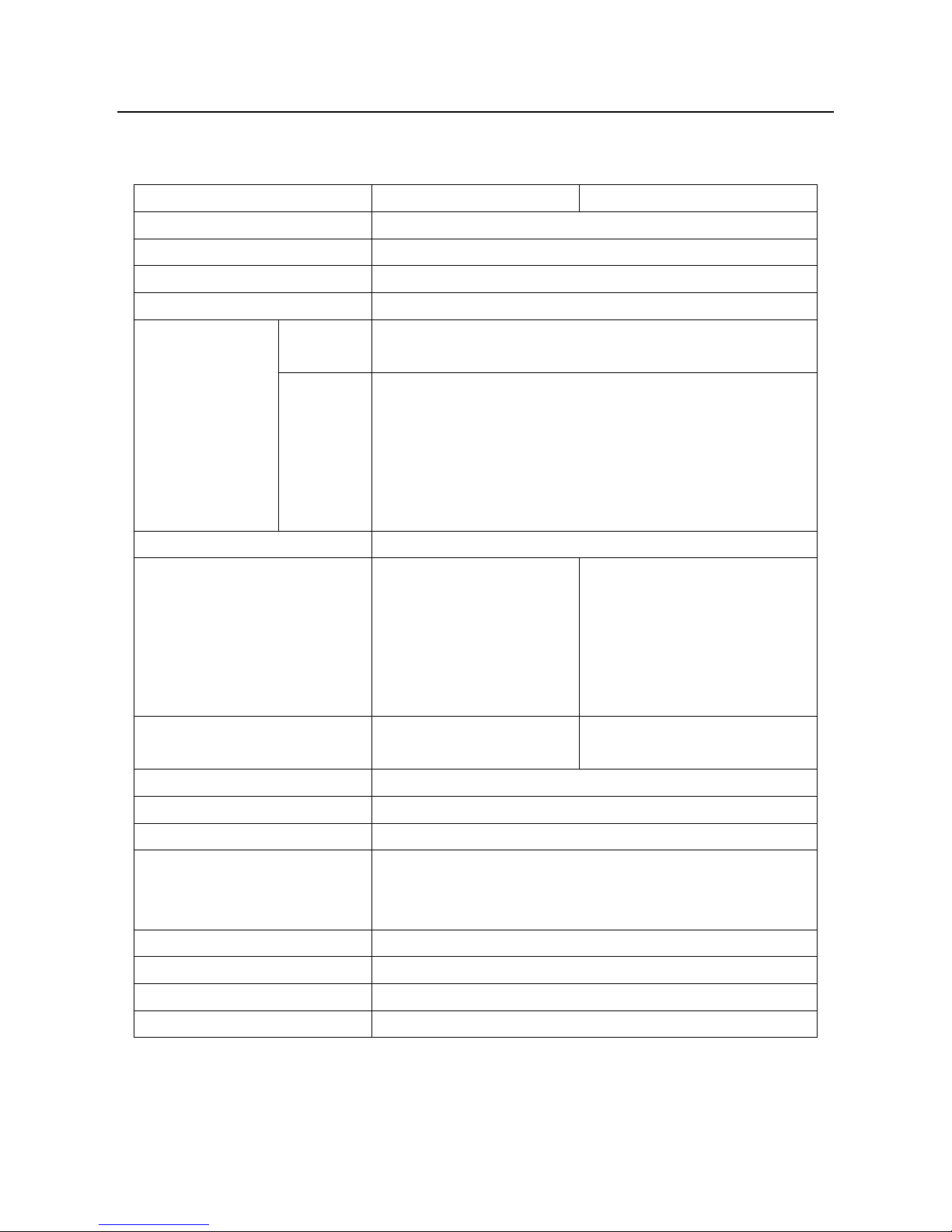
Technical Specifications – Pro2 / Pro2 Plus
Item
Pro2
Pro2 Plus
Power Supply Input
100-240 VAC, 50/60 Hz 230V@3.3A
Power Supply Output
24VDC 600W
User Interface Controller
Freescale imx6, Quad core 1Ghz ARM processor
Ports
SD card*1, USB 2.0*2, Ethernet*1
Network
Ethernet
Ethernet 802.11b/g/n
WLAN
IEEE802.11b/g:2412MHz to 2472 MHz
IEEE802.11n HT20:2412MHz to 2472 MHz
IEEE802.11a:5150 - 5250MHz, 5725 -5850 MHz
IEEE802.11an HT20:5150 - 5250MHz, 5725 -5850 MHz
IEEE802.11an HT :5150 - 5250MHz, 5725 -5850 MHz
Print Technology
FDM
Build Volume (W×D×H)
Single Extrusion Print:
12×12×11.8 inch
305×305×300 mm
Dual Extrusion Print:
11×12×11.8 inch
280×305×300 mm
Single Extrusion Print:
12×12×23.8 inch
305×305×605 mm
Dual Extrusion Print:
11×12×23.5 inch
208×305×605 mm
Machine Size (W×D×H)
24.4×23.2×29.9 inch
620×590×760 mm
24.4×23.2×43.5 inch
620×590×1105 mm
Filament Diameter
0.2/ 0.4/ 0.6/ 0.8mm
Print Head Travel Speed
30 - 150 mm/s
Max Build Plate Temperature
110 ºC
Supported Materials
PLA / ABS / HIPS / PC / TPU / TPE / NYLON / PETG / ASA / PP / Glass
Fiber Enforced Carbon Fiber Enforced / Metal Particles Filled / Wood
Filled
Nozzle Diameter
0.2/ 0.4/ 0.6/ 0.8mm
Max Nozzle Temperature
300 ºC
Operating Temperature
5-35 ºC
Storage Temperature
-25°C to +55°C
Page 7
COMPONENTS AND PARTS
Printer Components and Parts
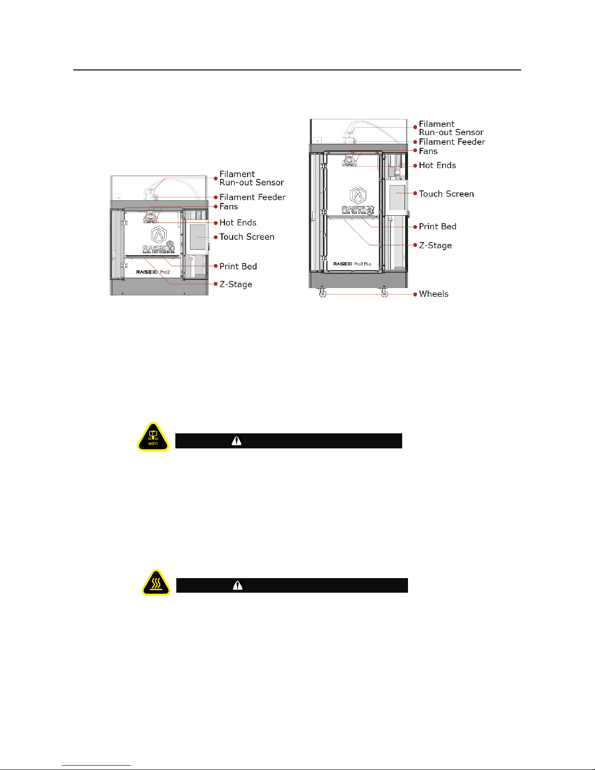
1. Front Parts
A Filament Run-out Sensor
That can detect whether filament has been run out.
B Filament Feeder
That’s part includes feeder motor and gear mechanical.
C Hot Ends
The hotend is made up of Nozzle,heater block, thermocouple, heater cartridge and heat sink. Nozzle
temperatures in the printer can exceed 300℃(572℉).
D Touch screen
That is human machine interface. All operation commands are from this. Some alarm information
can be displayed on the screen.
E Print bed
Print bed includes buildtak sheet and heat bed.
temperatures in the printer can exceed 110℃.
E Z-stage
That platform supports the print bed.
2. Rear Parts
WARNING
WARNING
Page 8

COMPONENENTS AND PARTS
WWW.RAISE3D.COM
AMERICA · ASIA · EUROPE
7
A Camera
That can monitor the printing process in remote place.
B Filament guide tube
This tube is perfect for minimizing bending and friction against the filament material.
C HEPA filter
That is designed to improve air quality on exhaust and deduce smell from filaments.
D Z ball screws
The parts can drive Z stage’s movement.
E USB storage slots
F Power inlet and Power switch
That is the power supply unit.
A 250V 10A fuse is located to protect the input power.
3. Bottom Parts.
Page 9

COMPONENENTS AND PARTS
WWW.RAISE3D.COM
AMERICA · ASIA · EUROPE
8
4. Electrical Parts
Page 10

SPARE PARTS
Spare Parts
Page 11

PRECAUTION AND INSTALLATION
Read the entire installation section before starting installation.
Connect equipment to a grounded facility power source. Do not defeat or bypass the ground lead.
• Know the location of equipment branch circuit interrupters or circuit breakers and how to turn them
on and off in case of emergency.
• Know the location of fire extinguishers and how to use them. Use only ABC type extinguishers on
electrical fires.
• Know local procedures for first aid and emergency assistance at the customer facility.
• Use adequate lighting at the equipment.
• Maintain the recommended range of temperature and humidity in equipment area.
• Do not use this product in an environment containing volatile or flammable compounds.
ENVIRONMENTAL REQUIREMENTS
• The 380mc and 450mc are for indoor use only.
• Air quality conditions with excessive solid particulates (conductive or
non-conductive) may result in system damage.
• Air quality conditions in which airborne oils are allowed to accumulate on or within the printer
can damage the plastic components.
• Operating temperature shall be in the range of 5°C to 35°C, with relative
humidity range of 30% to 70% non-condensing.
• Storage temperature shall be in the range of -40°C to 55°C, with relative
humidity range of 10% to 85% non-condensing.
• Altitude shall not exceed 6561.68 feet (2000 m).
• Noise emission (acoustic):
• <50dBA when building
Note: The 380mc and 450mc printers are capable of generating vibrations depending mainly on part build
geometry and material characteristics. This consideration will need to be taken into account if locating the printer
near vibration sensitive equipment.
Input Supply Connection
Installation and mains outlet socket shall be made and protected according to appropriate rules. Check the input
voltage, phase, and frequency supplied to this machine before turning it on. Verify the connection of grounding
wires from the machine to the input source. The allowable input voltages are 1x(90-240)V 50Hz/60Hz. For more
information about input supply refer to the technical specification section of this manual and to the rating plate of
AWARNING
Page 12

PRECAUTION AND INSTALLATION
WWW.RAISE3D.COM
AMERICA · ASIA · EUROPE
11
the machine. Make sure the amount of power available from the input connection is adequate for normal
operation of the machine.
After connecting the input cord to the machine, make the power switch on, the Pro2 / Pro2 Plus printer will start
to work.
Hardware Installation
Recommend to unclip the Zipties as you are able to
reuse the ties later.
Please remove the 24 clips holding the extruder
assembly in place before powering on your printer. If
you fail to remove these clips your printer will be
damaged. Please save these clips and re-install them
when you transport your printer.
Use the 3mm hex wrench to remove the Z axis clamps
on both Z axis ball screws.
The 3mm hex wrench is packed inside the tool box
located inside the top foam.
Page 13

PRECAUTION AND INSTALLATION
WWW.RAISE3D.COM
AMERICA · ASIA · EUROPE
12
Plug the machine into a wall outlet and power on. The
power cable is packed inside the tool box located inside
the top foam.
The printer will go through a start-up sequence. When
the touch screen displays "Home", the printer is ready.
Go to "Utilities" and press Z homing button to home
the Z print bed to origin position.
Take the starter box and filament box out from the
base of the printer. And open for standby.
Page 14

PRECAUTION AND INSTALLATION
WWW.RAISE3D.COM
AMERICA · ASIA · EUROPE
13
Select "10mm" for "Move Steps" and move Z platform
downward to 50mm.
Loose the two thumb screws in front of the build plate
with anti-clockwise rotation.
Take build plate off from the protective cover.
Please remove the leveling testing model carefully
from the build plate.
Page 15

PRECAUTION AND INSTALLATION
WWW.RAISE3D.COM
AMERICA · ASIA · EUROPE
14
Slide the build plate onto the Z platform. Face the
surface with Raise3D logo up.
Re-install the thumb screws back with clockwise
rotation.
Install the filament holder in the mount point on the
side of the printer and place a spool of filament on the
holder.
NOTE: The direction of filament spool should be placed
to rotate in clockwire at mount points B and D and
counterclockwise at mount points A and C.
Feed the filament through the guide tube.
Page 16

PRECAUTION AND INSTALLATION
WWW.RAISE3D.COM
AMERICA · ASIA · EUROPE
15
Press the “Utilities” menu on the screen and set the
temperature of the left nozzle for the filament, then
press the “Load” button. Finish the feeding operation
step by step according to the instructions on the
screen.
NOTE: This document is set based on the Raise3D PLA
filament, which is delivered together with the printer.
Therefore we advise that you use this PLA for testing.
Page 17

OPERATION
Operation
Even though Pro2/Pro2 Plus is preleveled in the
factory, please press X/Y axis ‘home’ button first and
then Z axis 'home' button to check whether the leveling
is changed during shipping.
Select "10mm" for "Move Steps" and move X to 50mm,
Y to 10mm.
Please use the feeler gauge to check the distance
between nozzle and printing platform. The optimal
distance between is 0.2mm.
The best condition of this is that you can feel a little
friction when you slide the feeler gauge into the gap.
The distance between the nozzle and the printing
platform can be adjusted by turning the thumb screw
on the left-front corner of the Z-plate, the higher the
screw stands out, the further the distance between the
nozzle to the printing platform gets.
The USB storage included with the printer comes
loaded already with sliced models. It is a good place to
start for your first print.
Insert the USB storage into the USB slot on the side of
touchscreen.
Page 18

OPERATION
WWW.RAISE3D.COM
AMERICA · ASIA · EUROPE
1
Select “Print” menu, choose “USB Storage” in the file
storage path. Select the file to check the printing
parameters and settings, then press “Print” to start
printing test file.
During printing, you can check status, printing time
remaining and other parameters from the touchscreen
in the “Home” interface.
NOTE: The image on the touch screen will only be
shown when the file is sliced by ideaMaker.
The .data file is saved in USB storage or uploaded to
screen.
WLAN Connection:
You can choose a network to join by inputting the password. When the WIFI module is manufactured, 2.4G is set
at HT20, 5GHz is set at HT40. The wifi’s frequency is fixed before being manufactured. The customer is not
allowed to modified WIFI’s parameter. If there’s needed, please connect Raise 3D.
Page 19

OPERATION
WWW.RAISE3D.COM
AMERICA · ASIA · EUROPE
2
Or Add Other Network with inputting its name and password.
Figure 1.40: Inputting Network’s Name
Page 20

WIRE DIAGRAM
Wire Diagram
MOTION CONTROL BOARD
SCREEN BOARD
SCREEN
Extruder board
CAERA
-12V+ -12V+ -12V+
+24V-
+24V-
+24V-
+
-
PRO2 / Pro2 Plus WIRE DIAGRAM
Raise3d
WIFI
Antenna
Page 21

WWW.RAISE3D.COM
AMERICA · ASIA · EUROPE
1
NOTES
 Loading...