

Page 1
N1
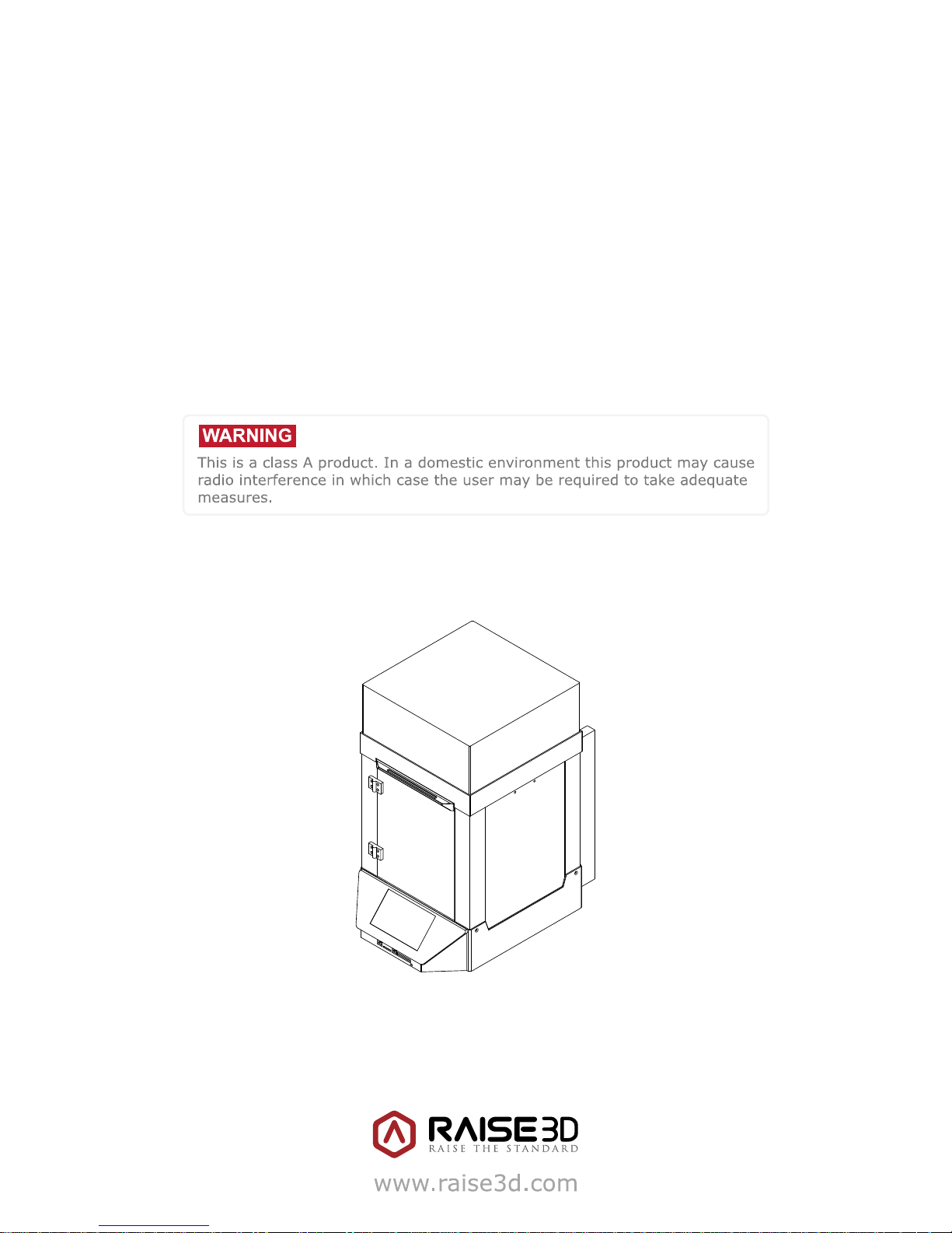
Quick Start Guide
N-Series 3D Printer
* Please review this entire guide before operating the printer.
Page 2
N-Series 3D Printer
/ Quick Start Guide
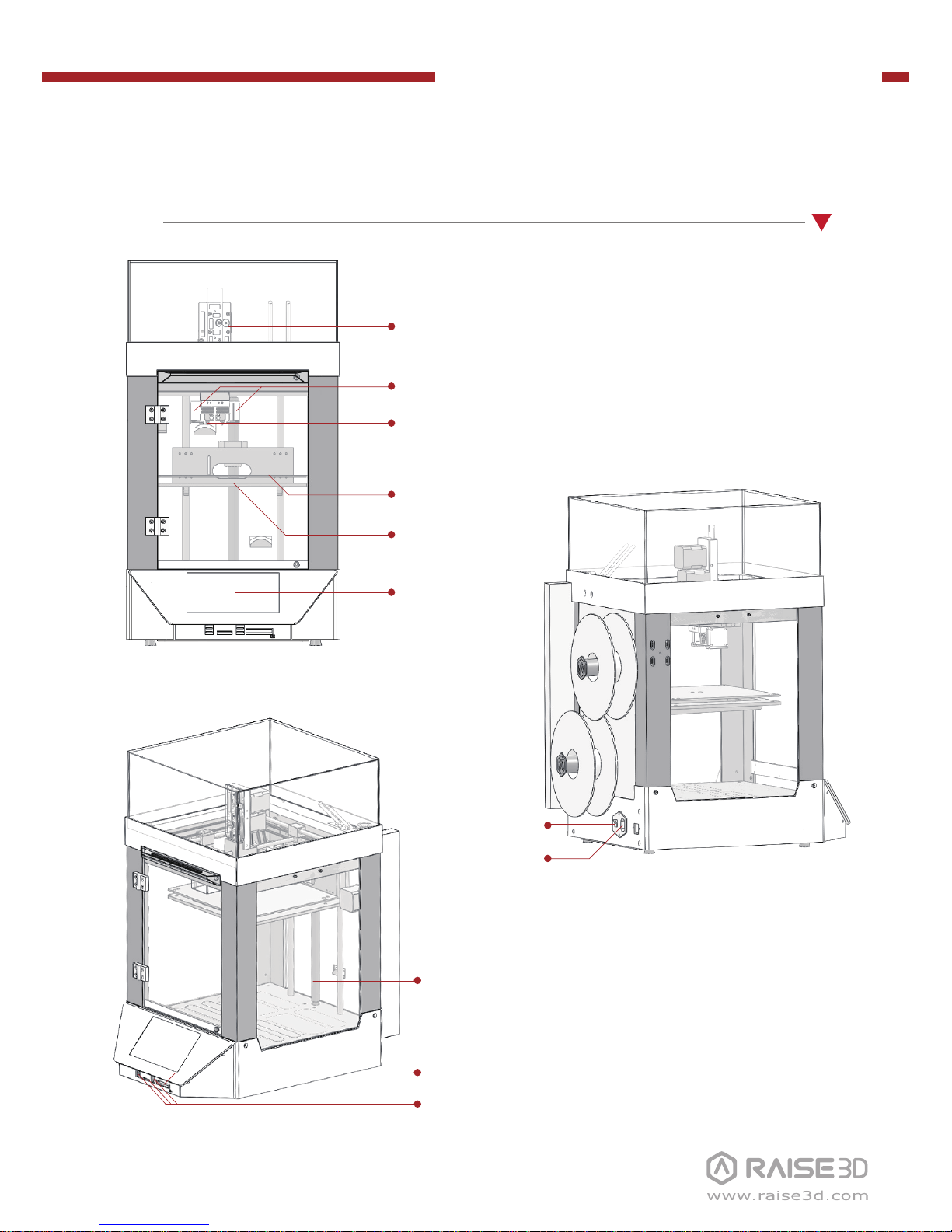
A List of Parts
N1
Touch Screen
Nozzle(s)
Fan(s)
Z-Stage
Print Bed
Filament Feeder
Z Ball Screws
Power Inlet
Power Switch
USB Storage & SD Card Slot
GPIO Ports
Page 3

N-Series 3D Printer
/ Quick Start Guide
B Hardware Installation
Please remove the 24 clips holding the
extruder assembly in place before powering on your printer. If you fail to remove
these clips your printer will be damaged.
Please save these clips and re-install them
if you transport your printer.
Remove!
3
(×24)
Untie the rope which fastens the accessory
box.
4
Recommend to unclip the Zipties as you
are able to reuse the ties later.
2
Remove!
Take the power cable out from the left
foam box for later using.
1
Remove!
Page 4
N-Series 3D Printer
/ Quick Start Guide
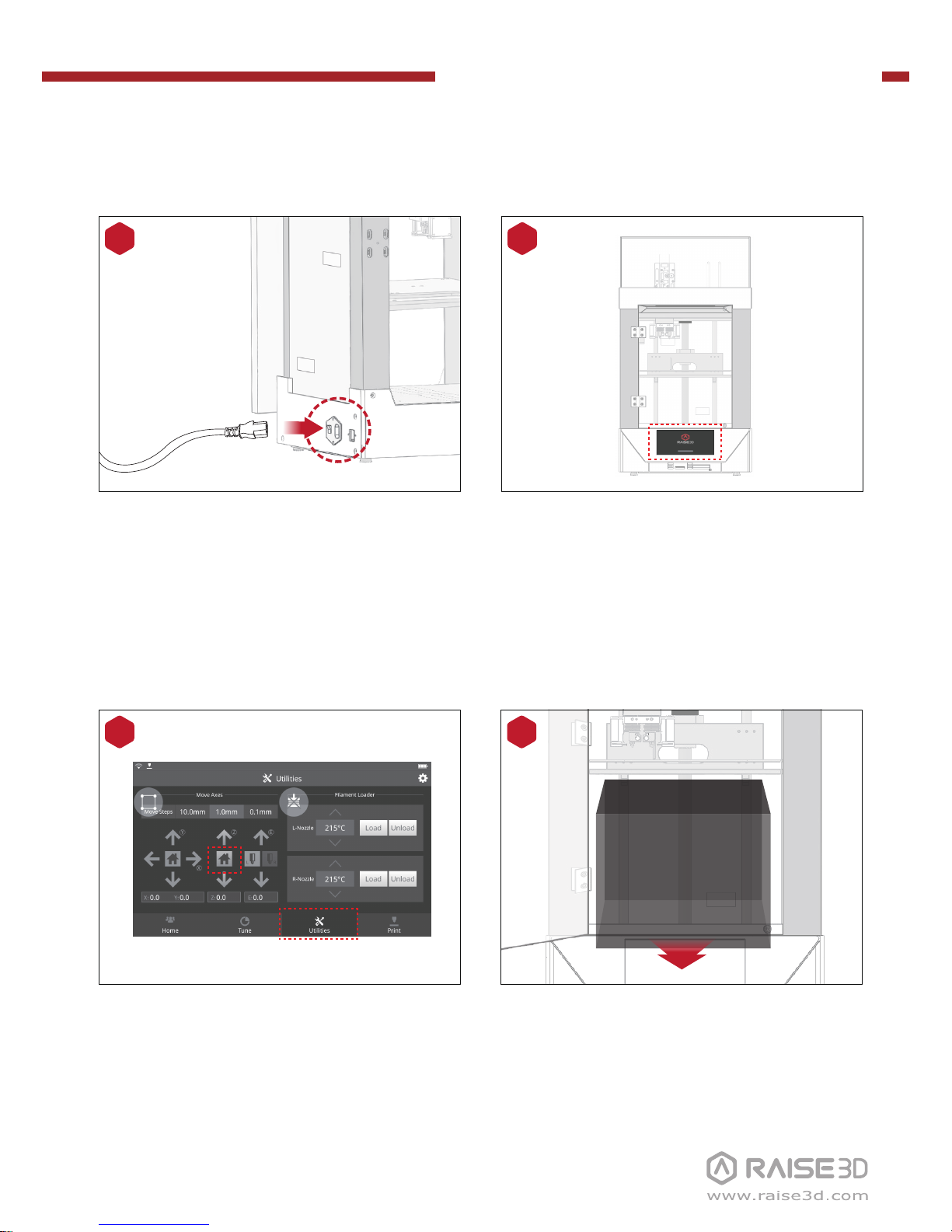
B Hardware Installation (continued)
The printer will go through a start-up
sequence. When the touch screen displays
"Home", the printer is ready.
6
When the Z axis return to original position,
gently lift the build plate gently with your
hands and remove the accessory bag
under the build plate and open it for
standby.
8
Plug in the power plug and turn the switch
on.
5
Select the “Utilities” menu on the screen.
Press Z “Home” button to raise the Z ball
screws to the highest point.
7
Page 5
N-Series 3D Printer
/ Quick Start Guide
B Hardware Installation (continued)
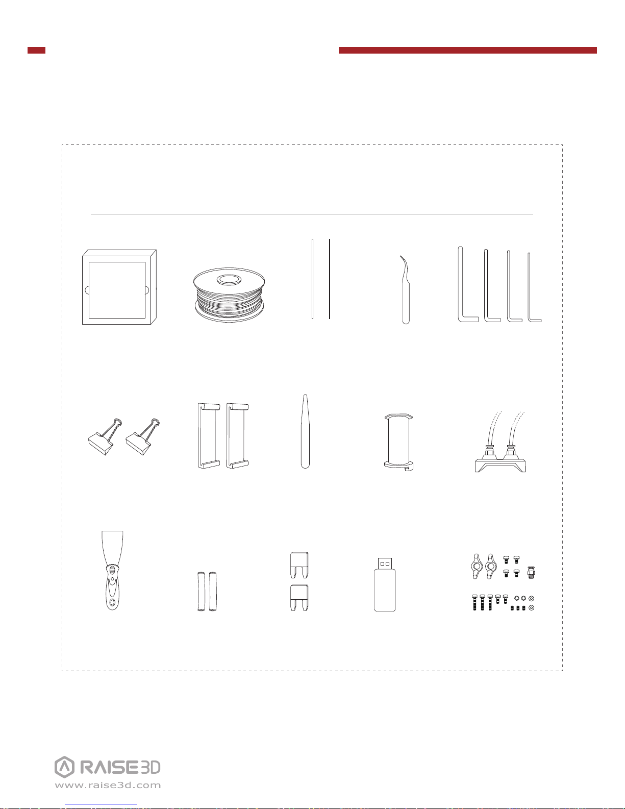
List of Contents
Spatula
Filament
(×1/×2)*
Filament Holder
(×1/×2)*
Nozzle
Cleaning Kit
Glass with
Protective Foam
Hex Wrenches
2.5mm 2mm 1.5mm3mm
Feeler GageFan Cover
(×0/×2)*
Tweezers
USB Storage
Filament Guide
Tube (×2/×4)*
Fuse
15A
10A
Build Plate Clips Filament Guide
Tube Holder
Other Accessories
(Spare)
* Due to the difference between single and dual extrusion machines, the quantity of some of the products
received will be different.
Besides, there is only one fan cover in the printer with single extruder and it is has already been equipped
to the printer.
Page 6
N-Series 3D Printer
/ Quick Start Guide
B Hardware Installation (continued)
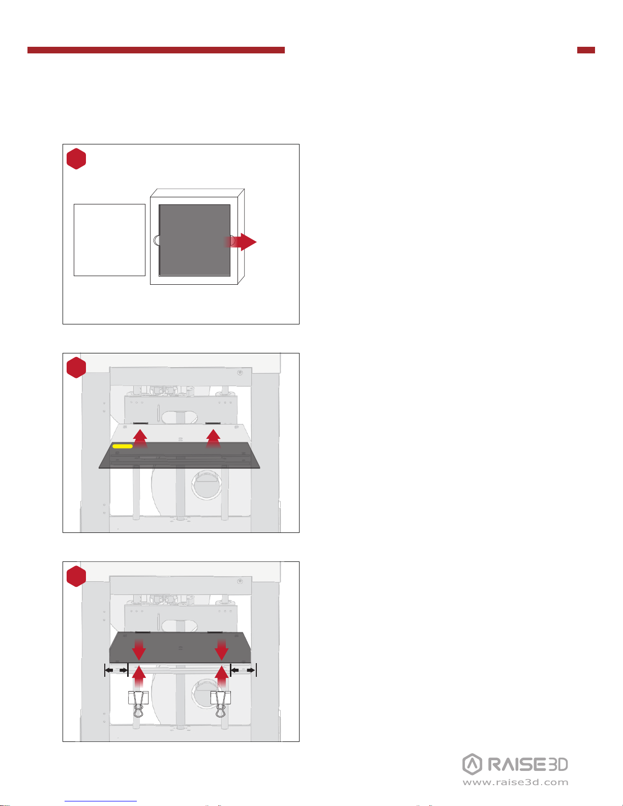
Remove the glass build plate from the
protective foam.
9
Gently slide the glass plate. Make sure it
snaps into the build plate clamps at the
back.
NOTE: Place the surface which posted with
BuildTak upwards, while the yellow label is at the
back left corner. Make sure it snaps into the build
plate clamps in this way.
10
Remove the remaining build plate clips
from the accessory box and secure them
to the glass and heated bed plate.
NOTE: The best distance between the glass clip
and the edge of print platform is 5cm.
11
Protective Foam
Cover
Build Plate
Remove!
5cm5cm
Page 7

N-Series 3D Printer
/ Quick Start Guide
B Hardware Installation (continued)
Install the filament holder in the mounting
hole on the side of the printer and place a
spool of filament on the holder.
NOTE: The filament should load clockwise.
A
B
14
Mounting
holes
Please follow the instructions of “Bed
Leveling Steps” on the screen and use the
feeler to adjust the build plate. Make sure
the distance between the nozzle and the
plate are all even at four corners. The best
condition is that you can feel a little
friction when you slide the feeler into the
gap.
12
Feeler Gage
“Bed Leveling Steps” could be viewed by
clicking the “Leveling” button on the
“Utilities” interface. Follow the instruction
on the screen and operate step by step
until the end.
13
Page 8

N-Series 3D Printer
/ Quick Start Guide
B Hardware Installation (continued)
Feed the filament through the guide tube.
16
Push the filament down to the feed gear
until the gear grips the filament.
NOTE: For your first set of prints please use the
left nozzle only. The printer has been pre-calibrated based on printing with the left nozzle in
the factory. If you want to print with the right
nozzle or dual extrufers, please follow the
instructions on aligning both extruders found
here: https://www.raise3d.com/pages/faq.
17
Press the “Utilities” menu on the screen
and set the temperature of the left nozzle
for the filament, then press the “Load”
button. Finish the feeding operation step
by step according to the instructions on
the screen.
NOTE: This document is set based on the
Raise3D PLA filament, which is delivered
together with the printer. Therefore we advise
that you use this PLA for testing.
15
Page 9

N-Series 3D Printer
/ Quick Start Guide
C ideaMaker Installation
Open the installer and choose the language. Set a path for installing ideaMaker then
click "Next".
1
The ideaMaker software is
available on the USB storage
included with your printer.
Or go to www.raise3d.com and
download the ideaMaker
software.
www.raise3d.com
Download ideaMaker
WINDOWS
Page 10

N-Series 3D Printer
/ Quick Start Guide
Click "Finish" and ideaMaker is installed.
Follow the instructions and click "Install". After the installation is finished, click "Next" to
go to the next step.
2
3
C ideaMaker Installation (continued)
Page 11

N-Series 3D Printer
/ Quick Start Guide
C ideaMaker Installation (continued)
Open the Disk Image for the ideaMaker installed on the USB storage included with your
printer or that you downloaded from www.raise3d.com.
MAC OS X
Page 12

N-Series 3D Printer
/ Quick Start Guide
The first time you open ideaMaker you will need to select your printer model from the
drop-down list.
1
D ideaMaker Initial Settings
Select the diameter of the filament. Press "Finish" to finish the initial settings.
NOTE: ALL N-Series printers use 1.75mm filaments.
3
Select the number of nozzles. Press "Next" to move on to the next step.
2
Page 13

N-Series 3D Printer
/ Quick Start Guide
E Using ideaMaker
Click the "+" button to import an .stl file or .obj file. You can download a file or use
the test model included in the USB storage.
1
Click the "Start" or “i” button to begin the slicing of the model.
2
Confirm your printer model and material, then select the proper slicing template.
Click “Edit” to select the type of Platform Addition and the type of Support.
3
Page 14

N-Series 3D Printer
/ Quick Start Guide
E Using ideaMaker (continued)
Click the “Save and Close” after selecting the type of Platform and the type of
Support to return to the last menu. Click the “Slice” to start slicing.
4
Save the sliced files (.gcode and .data) to your USB storage.
NOTE: File names that do not conform to the Western Latin character set may not
display properly.
5
Confirm that the files are saved and eject the USB storage.
6
Page 15

N-Series 3D Printer
/ Quick Start Guide
F Start First Print
During printing, you can check
status, printing time remaining and
other parameters from the touchscreen in the “Home” interface.
NOTE: The image on the touch screen is
only showing when the file is sliced by
ideaMaker and the .data file is loaded.
Select “Print” menu, choose “USB
Storage” in the file storage path.
Select the file to check the printing
parameters and settings, then press
“Print” to start printing test file.
The USB storage included with the
printer comes loaded with already
sliced models. They are a good place
to start for your first print.
Insert the USB storage into the USB
slot on the side of touchscreen.
4
USB Storage
6
5
Page 16

N-Series 3D Printer
/ Quick Start Guide
G User Interface
· X/Y/Z axies move/return to original position
· Disable motor button
· Load and Unload
function for the L&R
extruders.
· Moving step distance
setting
· Status bar*
· Menu title, Settings Button
· Taskbar
· Current model name,
total print time, current
printing status and
height
· Visual display of current
model
· Pause/Resume button
· Stop button
· Extruder and Heat Bed
temperature
· Printing parameters
and adjustment
· Check uploading list,
recovery task list, printing
statistics
· Choose where to load
the print job from
* Please make sure the battery icon on the status bar is fully charged (or the battery level is more than
95%). Only in this condition can you turn off the power switch.
Page 17

4th Floor, Building B5, 1600 North Guoquan Rd, Shanghai, China 200438
+86 21 65337855
3189 Airway Avenue, Unit F, Costa Mesa, CA 92626, USA
+1 888 963 9028
www.raise3d.com
help.raise3d.com
 Loading...